Note: Descriptions are shown in the official language in which they were submitted.
CA 02446055 2003-10-22
2
pAL,LET .T1G
'this invenEion is in the field of machines far assembling structures, and in
particular such
machines for assanbly of pallets used in the shipping of ~aods.
S,~I,CKGI(tO~llVD
Pallets, and especially wooden pallets are an essential corupanez~t xz~ the
shipping and
handling of oornmereial goods. The demand for pallets continue to increase
each year,
with the result that imprave~aaextts iai the apparatus and methods used in
their construction
are desirable. Pallets are constzucted by afisemhling a number of wood,
plastic or metal
members to pmduce a frarrte structure with internal support members and top
and bottom
surfaces upon which freight is placed and the pallet rests. While pallets can
be
constrctcted by hand, the development of machine methods of pallet
construction permits
an individual operator to build pallets more rapidly and safely.
Machines and methods for use in building pallets are known in the art, as
disclosed. for
example iii U.S. Patent 5,249,352 to Larders, Canadian Patent 1,193,424 to
Viitanen 8c
8illett and ~axzadian Patent 1,037,201-to Haywarth.
Typical pallet building machines, commonly called pallet jigs, such as
disclosed in
Larders, comprise a jig frame to position and align the members intended for
assembly
into tlxe pallet, and a number of'nailing guns'maunted on. a gantry frame.
Typically
pallet stzers are planed in the jig frame; then deck boards arc placed in the
jig frame on
top of the stringers. The stringer and deck beards are maintained in position
by elements
ofthe jig frame. The nailing guns on tha gantry frame are aligned with the
stringers, and
the gantry frame is mounted oz~ rollezs or the like so that the gantry frame
c;an he moved
along the jig frame parallel to the stringers. Thus each nailiztg gun is
movable along ozxe
3U stringer, and can drive typically two nails through each deck board and
into the stringer,
CA 02446055 2003-10-22
3
Springs are provided to bias the weight of the gantry frame upwards so that
the operator
can readily xxzove the gantry ~I~rarne up and down to #ire the nailing guns at
the desired
locations as the gantry frame moves along the jig firarne.
S Typically the nailitxg guns are fired by pressing the nose of the gurt down
on the board
and then continuing to move the nailing gun downward to move the nose inward
with
respect to the nailing ,gun - when the nose has moved inward a sufficiart
distance the gun
fires a nail into the board. Once the nose has moved inward sufficiently to
fire the gun., it
stops and tk~ezt substantially no;i'vrther inward movement of the nose with
respect to the
gun is possible.
The nailing guns are conventionally rigidly mounted to the gaz~tay ~raax~e, as
disclosed in
Lenders, so that the nose of each gun is at the same vertical lpcation with
respect to the
jig frame. Then as the gantry frame is moved down, each nose eonta,cts the
deck board at
the same time and, as the gantry frame is waved louver, each gun will fire at
substantially
the sine tame.
The conventional pallet jigs, as exemplified by Lenders, operate
satis~factoxily when the
deck boards and stringers have a consistent thickness: The surface of the deck
board is
then located at the same vertical location with respect to the jig frame under
each nailing
gun. When the gantry frame is moved down, the nose of each gun will contact
the
surface at the same time and will fiure at the same time.
A problem is encountered however where the deck boards do not have a
consistent
~5 thickness. Commonly pallets are used in applicatxcsns where a rough deck
surface ~uvauld
be satisfac,~tory, and thus it would be more economical to use rough deck
boards that were
not planed to a consistent thickness. With such boards, the nose of o~ae
nailing gun will
contact the highest portion of the rough board before the noses of the other
guxzs contact
the board surface. As the gantry frame is waved lower, the other noses will
contact he
~0 board surface Later. The first gun to contact the board will drc before the
others, and
CA 02446055 2003-10-22
prevent further downward movement of the gantry frame, since the nailing guns
are
rigidly fired to the gantry frame. 'l7Vhere the thickness di;fferentaal is
large enough, one or
more of the other nailing ,guns xuay z.~ot then fixe and a nail is missed in
the pallet.
similarly where one stringer is slightly higher than another the same problem
will occur.
In order to satisfactorily use the prior art pallet jigs both stringers and
floor boards must
be consistently dimensioned, requiring the use of higher cost planed stringers
and deei~
boards even where the end use could be satisfactorily satisfied by a pallet
made of rough
boards.
14
sUlv(lvr~ltY' o;~ T~~ tf~lv~N rrpl~t
It is an object of the present invention to provide an apparatus for building
pallets that
IS overcomes problems in the prior art. Xt is a further object of the present
invention to
provide such an apparatus that provides satisfactory vpu"ration when making
pallets from
members with inconsistent dimensions.
It is a further object of the present invention to provide such an apparatus
comprising
nailing guns that are independently and movably rnountcd to the agparatus and
biased
20 downward in the direction of nailing.
The ittvention provides, in one cmbodirncnt, an apparatus for building pallets
comprising a
jig frame adapted to maintain a plurality of deelc boards in deck board
locations on tap of
a plurality of stringers in parallel strin~cr locations. ~1 gantry frame is
mounted above the
2~ jig frame and a plurality of nailing guns is mounted an the gantry frame.
The gantry
frame is movable with respect to the ji,~ frame to position and operate tlae
nailing stns t4
nail deck boards tv stringers. At least one nailing gtm is mounted. to the
gantry frame
such that the at least one nailing gun can move up and down with respect to
the gantry
frame, and the at least one nailing gun is biased toward a lowest gun
position.
CA 02446055 2003-10-22
In a second embodiment the invention provides an apparatus For building
pallets
GOxA7.pTi5ZJ~lg a jig .frame adapted to maintain a plurality of deck boards in
deck board
locations on top of a plurality of stringers in parallel stringer locations. A
gamtry Frame is
mounted above the jig .frame such that the gantry frame can move substantially
parallel to
the stringer locations, and can move up and down. A plurality of nailing guns
is mounted
an the gantry frame such that a nailing gun is mounted on the gantry frame
above each
stringer location. Each nailing gun is mounted to the gantry frame such that
each nailing
gun can move up amd down with respect to the gantry ti ame, and each nailing
gun is
biased toward a lowest gm position by a force sufficient to force a nose of
the nailing
gun against a deck board and fire the nailing gun.
With the apparatus of the invention, the nailing guns are able to move up and
down to
compensate far inconsistencies in the dimensions of the membera used to build
the pallet.
't~Vlaen the ~trst gun fires, the gantry can continue to move down to litre
the rest of the
guns, since the first gun can move up a:I~er it fires, rather than preventing
further
downward movement of the gantry, as in conventional pallet jigs. The operator
can then
move the gantry assembly to the next deck board location, repeating the
process until all
the deck boards have been nailed onto the stringers. Once all the top deck
boards are
secured, the partially completed pallet is turned over, axxd the operator cant
thext use the
apparatus to secure the bottom deck boards, thereby cvlrlplehllg the pallet.
DESCRIPTION OF THE DRAWINGS
While the invention is claimed an the concluding portions hereof, preferred
embodiments
are provided in the accompanying detailed description which may be best
understood in
conjunction with the accompanying diagrams where like parts in each of the
several
diagrams are labeled with like numbers, and where:
CA 02446055 2003-10-22
Fig. 1 is a schematic perspective view of az~ embadazneztt of the ioventxa~a;
Fig. 2 is a side view of a nailing gun mount ll1 WhlCh the naIllllg dull is
pivotally mounted
an the gantry frame;
Fig. 3 is a side view of a nailing gun mount in which the nailing gun is
slidably mounted
on the gantry frame.
DETAILED DESCRIPTI ~T:_O_F THE:IL>l~ TED EMIiODIMEffI'S
Fig. x . illustrates an apparatus l for building pall GtS emhod~ing the
present invention.
The apparatus 1 comprises a base portion 2 upon which is rnountod a jig frame
3. The jig
frame 3 comprises a plurality of stringer locations 4 and deck board locations
S, which
arc conveniently configured to be adjustable. Typically the deck boards are at
right
angles to the stringers, as illustrated.
A gantry frame b pivots about a gantry pivot axis GPA such that the gantry
frame ~ can
move up and down relative to the jig frame 3. The gantry frame 6 is also
mounted so that
it c:an move substantially parallel to the stringer locations 4. In the
illustrated
embodiment, the gantry frame is schematically illustrated to be on rollers 7
that engage a
track on the ji$ frame 3, however other mechanisms could be used as well. The
gantry
frame 5 is moved manually by gasping a control handle 12.
The gantry frama 6 cornprisos a gun mount rail 8. Gun mount brackets 9 are
fixed to the
gun rzxou~nt rail $, and gun mounts 1 p are movably attached to the gun mount
brackets
such that the gun mounts 1 Q can move up and down with respect to the ,gun
mount
brackets 9. A uazlaz~g gain 1 x is axed to each gun mount 1 D.
CA 02446055 2003-10-22
7
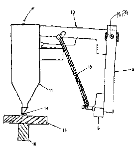
The movable attachment of the gun mount 10 is sho~avn as pivotal in Fig: ~,
wherein the
guxz nctount 10 is pivotally attached to the gun mount support znezxrber 9
about a gun
mount pivot axis MPA. Fig. 3 shows an alternate slidable attacbaxxent of the
gun mount
1d wherein the attachment of the movable gun mount 10 to the Burr mount
support
member 9 comprises a slidable sleeve 20: In both embodizxaents a downward bias
force is
exerted on the gUn mount 10 by a bias element, illustrated as a spring '13
although the
bias force could also be provided by a resilient hand, oz~ pressurized
extendable cylinder.
A stop is provided so that when the apparatus is at rest, the ~zaaliag guns
will be a lowest
gun position.
It is contemplated that the pivotal attachment of Fig. 2 will generally
provide the mast
convenient and economical movable attachment of the gun mount 10 to the gun
mount
support m9, however the slidable attachzxxent may be satisfactory in some
situations.
In constructing a pallet, a stringer board is placed in each stringer location
3, and a deck
boanl is placed in each deck board location 5. The jig frame 4 holds the
stringers and
deck boards in a substantially fixed position during the assembly of the
pallet. The
gantry frame 6 is then moved on the rollers 7 in a direction parallel to the
stringers and
downward to position the nailing guns 1 x in the desired nailing location at
an intersection
of a deck board 15 with a stringer 16, as illustrated in Figs. 2 and 3. There
is a nailing
gun 11 mounted on the gantry frame fl above each stringer I6 such that each
nailing gun
moves slang the stringer 16.
The gantry frame 5 and nailing guns 11 are lowered towards the deck board 15.
Each
gun nose 14 is forced against the deck board 15 and moves up and into the
nailing gun
11, thereby actuating the firing mechanism of the nailing gun 11, and driving
a nail into a
deck board 15 and underlying stringer board 16, scouring the deck board 15
anal stringer
board 16 together.
CA 02446055 2003-10-22
'the downward bias force of the spring 13 is sufficient to force the gun nose
14 toward
the nailing gun 11 to face the nail, but can be overcome by the operator to
move the
gantry frame 6 down afrex any one nailing gun has fired in order to ensure
that all the gun
noses 14 have been forced agahast the deck board 15, and each mailing gun 11
has fired a
nail into the desired locatio~z. Where there are inconsistencies in the
dimensions of the
members used to build the pallet, the indepezzdent znaux~ting of eavh nailing
gun 11 thus
permits the gantry frame G to continue to be lowered until all nailing guns 11
contact the
underlying deck board 15 with sufficient force to compress the nailing gun
nose I4 and
fire a nail.
The gantry frame 6 is then repositioned along the jig frame 3 to the next nail
location, and
the process repeated until all the deck boards and stringer boards are secured
with nails.
~1t this paint the partially completed pallet is removed fraz~a the jig frame
3, and if desired
can be flipped over, and desk hoards secured onto the opposite side of the
stringer boards
to cvmglete the pallet.
The foregoing is considered as illustrative only of the principles of the
invention.
Further, since nurneraus changes and madi$cations will readily occur to those
skilled in
the art, it is not desired to limit the invention to the exact construction
and operation
24 shown and described, and accordingly, all uch suitable changes or
modifications in
stmct~re or operation which may be resorted. to are intended to fall within
the scope of
the claimed invention.