Note: Descriptions are shown in the official language in which they were submitted.
CA 02446213 2008-10-23
Specification
Secondary Battery System Allowing A High Overload Operation
Technical Field
The present invention relates to a secondary battery system and,
more particularly, to a redox flow battery that can allow a high overload
operation even in case of emergency such as electric power failure.
Background Art
FIG. 6 is an explanatory view showing an operating principle of a
redox flow battery. As illustrated therein, the redox flow battery has a
cell 1 separated into a positive electrode cell lA and a negative electrode
cell lB by a membrane 4 of an ion-exchange membrane. The positive
electrode cell 1A and the negative electrode cell 1B include a positive
electrode 5 and a negative electrode 6, respectively. A positive electrode
tank 2 for feeding and discharging positive electrolytic solution to and from
the positive electrode cell 1A is connected to the positive electrode cell lA
through conduit pipes 7, 8. Similarly, a negative electrode tank 3 for
feeding and discharging negative electrolytic solution to and from the
negative electrode cell 1B is connected to the negative electrode cell 1B
through conduit pipes 10, 11. Aqueous solution containing ions that
change in valence, such as vanadium ion, is used for the positive and
negative electrolytes. The electrolyte containing the ions is circulated by
using pumps 9, 12, to charge and discharge the electrolyte with the change
in ionic valence at the positive and negative electrodes 5, 6. When the
1
CA 02446213 2003-10-31
electrolyte containing the vanadium ions is used, the following reactions
occur in the cell during the charge and discharge of electricity:
Positive electrode: V4+--V5++e- (Charge) V4+E--V6++e- (Discharge)
Negative electrode: V3++e---*V2+(Charge) V3++e-f--V2+ (Discharge)
FIG. 7 is a diagrammatic illustration of construction of a cell stack
used for the redox flow battery mentioned above. This type of battery
usually uses the construction which is called a cell stack 100 comprising a
plurality of cells stacked in layers. Each of the cells has the positive
electrode 5 and the negative electrode 6 which are made of carbon felt and
disposed at both sides of the membrane 4. It also has cell frames 20
disposed at the outside of the positive electrode 5 and at the outside of the
negative electrode 6, respectively.
Each of the cell frames 20 has a bipolar plate 21 made of carbon
plastic and a frame 22 formed around the outside of the bipolar plate 21.
The frame 22 has a plurality of holes which are called manifolds 23A,
23B. The manifolds 23A, 23B are arranged to form flow channels of the
electrolytic solutions when a number of cells are stacked in layers and
communicate with the conduit pipes 7, 8, 10, 11 of FIG. 6.
The redox flow battery is usually used with the aim of allowing
load-leveling through the steady operation that electricity is discharged
during daytime when more electric power consumption is required and
electricity is charged (stored) during nighttime when less electric power
consumption is required. For the load-leveling, high efficient operation of
the battery is desirable from the viewpoints of energy saving and cost
reduction. On the other hand, in case of emergency such as an
2
CA 02446213 2003-10-31
instantaneous electric power failure in the steady operation, it is desirable
to bypass the efficient operation in favor of highest possible overload
operation of the battery. It should be noted here that the term "overload
operation" means operation at an output in excess of a rated output, and
the term "rated output" means an output at which energy efficiency during
the charge/discharge of electricity reaches a design value or more. In
general, the rated output is often set at about 80% of the maximum output.
The redox flow battery can allow a comparative high overload
operation when it is in the fully charged state, but it cannot allow the
overload operation substantially when electric energies stored in the
electrolyte are less at the end stage of discharge or after the end of
discharge.
This is because when the electrolyte is high in state of charge, the
redox flow battery can allow a high overload output, while however, when
the electrolyte drops in state of charge, the voltage is reduced, making it
hard for the redox flow battery to allow the overload output. The
expression "the electrolyte is high in state of charge" indicates the state
that when a vanadium-based electrolyte is used for the electrolyte, the
electrolyte for the positive electrode has a high ratio "(concentration of
quinquevalent vanadium ions)/(concentration of tetravalent +
quinquevalent vanadium ions)" and the electrolyte for the negative
electrode has a high ratio "(concentration of bivalent vanadium
ions)/(concentration of bivalent+trivalent vanadium ions)".
For allowing this overload operation, the conventional redox flow
batteries require a largely increased amount of electrolyte and also require
3
CA 02446213 2003-10-31
that the electrolyte be constantly kept high in state of charge even after
discharging in the steady operation. However, the load-leveling operation
requires a fluid volume of electrolyte corresponding to its capacity of a few
hours or more, and to obtain the constant increase in the state of charge by
increasing the fluid volume of electrolyte requires a significantly large
amount of electrolytes.
Accordingly, it is a primary object of the present invention to provide
a secondary battery system that can allow a high overload operation even
in the discharge state during the steady operation, and an operating
method thereof.
Disclosure of the Invention
In order to accomplish the object mentioned above, the present
invention is constructed so that electrolytes having a high state of charge
for an emergency operation are reserved, in addition to electrolytes for a
steady operation, so that when an accident such as electric power failure
occurs, the electrolytes for emergency operation are fed to a battery cell
reliably.
Specifically, the present invention provides a secondary battery
system comprising at least one set of first tanks for reserving electrolytes
required for a steady operation, at least one set of second tanks for
reserving electrolytes required for an emergency operation, and switching
means for allowing selective switching between the electrolytes in the first
tanks and the electrolytes in the second tanks to circulate the selected
electrolytes through a cell, wherein the electrolytes reserved in the second
tanks are electrolytes having a proportion of a quantity of active material
4
CA 02446213 2003-10-31
produced in a charging reaction to a total quantity of active material of not
less than 50%.
During the steady load-leveling operation, the electrolytes in the first
tanks are used to charge and discharge electricity. During the emergency
operation such as electric power failure, the electrolytes in the first tanks
are switched to the electrolytes in the second tanks, then discharging
electricity. As a result of this, the electrolytes in the second tanks that
are
kept high in state of charge are fed to the cell at any time, so that the high
overload operation is ensured, regardless of the discharge condition of the
first tanks.
For determining an output value of an electrical overload output at a
high overload rate during the operation, the state of charge of the
electrolytes fed to the cell is a more important factor than a total capacity
of the electrolytes remaining in the tanks. Due to this, even when a large
quantity of electrolyte of a low state of charge is contained in the tanks,
they do not produce the expected output of the overload.
In general, a quantity of electrolyte corresponding to the capacity of
the order of eight hours is required for charge or discharge of electricity
for
a load-leveling purpose. On the other hand, a quantity of electrolyte
corresponding to the capacity of the order of two hours at largest is just
required for electricity required for an emergency operation such as for
example during the time of electric power failure. Due to this, when the
state of charge is tried to be always kept high by increasing a quantity of
electrolyte without the switching of the electrolyte, as conventionally, a
large quantity of electrolyte is required and the tanks are also required to
5
CA 02446213 2003-10-31
be increased in size. In contrast to this, when the switching of the
electrolytes according to the present invention is used, a relatively small
quantity of electrode is only required for emergency operation and thus the
second tanks of a smaller size than the first tanks is also required.
It is to be noted here that the term "a set of' used for both the first
tanks and the second tanks means that a tank for reserving the positive
electrolyte and a tank for reserving the negative electrode are paired.
Electrolyte that is in a substantially fully charged state or in a nearly
fully charged state is used for the electrolytes reserved in the set of second
tanks. In other words, the electrolyte of high in state of charge is used
therefor. The expression "the electrolyte is high in state of charge"
indicates the state that when a vanadium-based electrolyte is used for the
electrolyte, the electrolyte for the positive electrode has a high ratio
"(concentration of quinquevalent vanadium ions)/(concentration of
tetravalent + quinquevalent vanadium ions)" and the electrolyte for the
negative electrode has a high ratio "(concentration of bivalent vanadium
ions)/(concentration of bivalent + trivalent vanadium ions)". It is
preferable that a ratio of (concentration of quinquevalent vanadium
ions)/(concentration of tetravalent+quinquevalent vanadium ions) is the
order of not less than 50% and a ratio of (concentration of bivalent
vanadium ions)/(concentration of bivalent+trivalent vanadium ions) is the
order of not less than 50%.
Valves are preferably used as the switching means. Preferably, the
secondary battery system comprises an association mechanism for
controlling the switching means on the side on which the electrolytes are
6
CA 02446213 2007-03-06
a
discharged from the first tanks or the second tanks and the switching
means on the side on which the electrolytes are fed to the first tanks or the
second tanks in association with each other. This associated switching
operation can allow balancing of a quantity of electrolytes discharged from
the tanks and a quantity of electrolytes fed to the tanks at the switching of
the tanks, to prevent imbalance of quantity of electrolytes in the cell or
generation of considerable pressure change. The associated control of the
switching means can be easily realized by electrically controlling the
open/close of the valves.
It is preferable that there are provided electrolyte circulation pumps
between the switching means on the side on which the electrolytes are
discharged from the first tanks or the second tanks and the cell. This
arrangement can provide the result that the pumps for the first tanks and
the pumps for the second tanks can be combined for common use.
Needless to say, the pumps for feeding the electrolytes from the first tanks
to the cell and the pumps for feeding the electrolytes from the second tanks
to the cell may be provided separately from each other.
Further, the present invention provides an operating method of a
secondary battery system which in case of emergency operation allows a
switching to electrolytes for emergency operation of at least equal in state
of charge to electrolytes for steady operation.
According to an aspect of the present invention there is provided a method of
operating a secondary battery system, the secondary battery system including
at
least one set of first tanks for reserving electrolytes required for a steady
operation,
at least one set of second tanks for reserving electrolytes required for an
emergency
operation, and switching means for allowing selective switching between the
7
CA 02446213 2007-03-06
electrolytes in the first tanks and the electrolytes in the second tanks to
circulate the
selected electrolytes through a cell, the method comprising:
reserving electrolytes having a proportion of a quantity of active material
produced in a charging reaction to a total quantity of active material of not
less than
50% in the second tanks for the emergency operation;
using the electrolytes in the first tanks to charge and discharge electricity
to ensure
operation at a rated output during the steady operation;
switching from using the electrolytes in the first tanks to using the
electrolytes in
the second tanks during the emergency operation; and
using the electrolytes in the second tanks to charge and discharge electricity
to
ensure an overload operation at an output in excess of the rated output during
the
emergency operation.
Brief Description of the Drawings
FIG. 1 is a diagrammatic illustration of construction of a redox flow
battery system of the present invention. FIG. 2 is a graph showing the
properties of the redox flow battery when discharging in its fully charged
7a
CA 02446213 2003-10-31
state. FIG. 3 is a graph showing the properties of the redox flow battery
when discharging from the end stage of discharge. FIG. 4 is a
diagrammatic illustration of a part of a shared-pump type of redox flow
battery system of the present invention. FIG. 5 is a diagrammatic
iIlustration of a part of a redox flow battery system having a plurality of
cell stacks of the present invention. FIG. 6 is an explanatory view of an
operating principle of a redox flow battery. FIG. 7 is an illustration of
construction of a cell stack of the redox flow battery.
Best Mode for Carrying out the Invention
In the following, certain preferred embodiments of the present
invention are described.
(First embodiment)
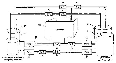
FIG. 1 is a diagrammatic iIlustration of construction of a redox flow
battery system of the present invention.
This battery system comprises a single cell stack 100, two sets of
tanks 31, 32 and 33, 34 for reserving electrolytes, valves 41-48 for allowing
switching of the electrolytes contained in the tanks 31-34, to selectively
supply the electrolytes to the cell stack 100, and pumps 51-54 for
circulating the electrolytes.
The cell stack 100 is identical in construction to the conventional one,
as illustrated in FIGS. 6 and 7.
The tanks 31-34 comprise the first tanks 31, 32 for supplying the
electrolytes to the cell stack for the purpose of load-leveling during the
steady operation and the second tanks 33, 34 for supplying the electrolytes
to the cell stack in an emergency operation, such as during the time of
8
CA 02446213 2003-10-31
electric power failure. The first tanks and the second tanks comprise
positive electrolyte tanks 31, 33 and negative electrolyte tanks 32, 34,
respectively.
Vanadium-based electrolytes are used for the electrolytes reserved in
the first tanks and the second tanks. The positive electrolyte contains V4+
/Vfi+ ions and the negative electrolyte contains V3+/V2+ ions.
Fully charged electrolytes are used for the electrolytes reserved in the
set of second tanks 33, 34. The electrolyte having a high ratio of
"(concentration of quinquevalent vanadium ions)/(concentration of
tetravalent+quinquevalent vanadium ions)" may be used for the positive
electrode and the electrolyte having a high ratio of "(concentration of
bivalent vanadium ions)/(concentration of bivalent + trivalent vanadium
ions)" may be used for the negative electrode.
There are provided a total of eight valves 41-48, including the valves
41, 42 for controlling the supply of the electrolyte from the set of first
tanks
31, 32 to the cell stack 100, the valves 43, 44 for controlling the discharge
of the electrolyte from the cell stack 100 to the set of first tanks 31, 32,
the
valves 45, 46 for controlling the supply of the electrolyte from the set of
second tanks 33, 34 to the cell stack 100, and the valves 47, 48 for
controlling the discharge of the electrolyte from the cell stack 100 to the
set
of second tanks 33, 34.
There are provided a total of four pumps 51-54, including the pump
51 for feeding the positive electrolyte from the first tank 31, the pump 52
for feeding the negative electrolyte from the first tank 32, the pump 53 for
feeding the positive electrolyte from the second tank 33, and the pump 54
9
CA 02446213 2003-10-31
for feeding the negative electrolyte from the second tank 34.
In the redox flow battery system thus constructed, during the steady
operation for load-leveling and the like, the electrolytes in the first tanks
31, 32 are used for the charge and discharge of electricity. During this
steady operation, the pumps 53, 54 are put in its inoperative state, with
the valves 45-48 closed, while on the other hand, the pumps 51, 52 are
bought into operation, with the valves 41-44 opened. In the steady
operation, when the electrolytes in the first tanks are high in state of
charge, such as, for example, immediately after electrically charged, the
redox flow battery can allow a high overload operation, while however, at
the end stage of discharge or after completion of discharge, it is too hard
for
the redox flow battery to allow the high overload operation.
FIG. 2 is a graph showing the properties of the redox flow battery
when discharging in its fully charged state. FIG. 3 is a graph showing the
properties of the redox flow battery when discharging at the end stage of
discharge. The graph of FIG. 2 shows a discharge curve plotted when a
battery having a capability of about two hours at a discharging rate of
60mA/cm2 is discharged in its fully charged state of 1.55V. The graph of
FIG. 3 shows a discharge curve plotted when the battery having a
capability of about two hours at a discharging rate of 60mA/cm2 is
discharged for one hour and forty-eight minutes, first, and, then,
discharged in its charged state of 1.21V. It will be understood from
comparison between both graphs that the battery can allow an output at a
high voltage when it is in the state in which the electrolyte is fully charged
to be high in state of charge, while on the other hand, it can allow
CA 02446213 2003-10-31
substantially no overload operation when it is at an end stage of discharge
at which the electrolyte is low in state of charge to cause a significant drop
of voltage in the cell leading to a stop of discharge.
On the other hand, during an emergency operation, such as during
the time of electric power failure, the electrolytes to be fed to the cell
stack
100 are switched from the electrodes in the first tanks 31, 32 to the
electrodes in the second tanks 33, 34 to discharge electricity, so as to allow
the high overload operation. The switching is controlled by closing the
valves 41-44 and stopping the pumps 51, 52 and, then, opening the valves
45-48 and bringing the pumps 53, 54 into operation. Since the electrolytes
in the second tanks 33, 34 are kept high in state of charge, the battery can
allow the high overload operation at any time, regardless of the state of
charge of the electrolytes in the first tanks.
It is preferable that when the electrolytes to be fed to the cell stack
are switched, switching operation of the valves 41, 42, 45, 46 arranged on
the side on which the electrolytes are discharged from the first and second
tanks and switching operation of the valves 43, 44, 47, 48 arranged on the
side on which the electrolytes are fed to the first and second tanks are
controlled in association with each other. This associated switching
operation of the valves can allow balancing of a quantity of electrolytes
discharged from the tanks and a quantity of electrolytes fed to the tanks at
the switching of the tanks, to prevent imbalance of quantity of electrolytes
in the cell or generation of considerable pressure change.
(Second Embodiment)
While in the first embodiment, the pumps 51, 52 and the pumps 53,
11
CA 02446213 2003-10-31
54 are placed for the electrolytes of the first tanks 31, 32 and the second
tanks 33, 34, respectively, the pumps for each set of tanks may be
combined for common use. FIG. 4 is a diagrammatic illustration of a part
of a shared-pump type of redox flow battery system of the present invention.
In this illustration, like reference characters refer to corresponding parts
of
FIG. i.
As illustrated, pumps 55, 56 are interposed between an intermediate
part of piping between the valves 41, 45 and the cell stack 100 and between
an intermediate part of piping between the valves 42, 46 and the cell stack
100, respectively, for connection between the valves and the cell stack.
This can allow selective switching between the electrolytes in the first
tanks and the electrolytes in the second tanks and circulation of the
selected electrolytes by using a total of two pumps 55, 56.
The switching operation (open/close operation) of the valves41-48
required for the switching of the electrolytes is identical with that of the
first embodiment.
(Third Embodiment)
Further, a diagrammatic illustration of a part of a redox flow battery
system having a plurality of cell stacks 100-102 is shown in FIG. 5. In
this third embodiment as well, the selective switching between the
electrolytes in the first tanks and the electrolytes in the second tanks is
controlled by the valves 41-48 being opened and closed in the same manner
as in the first embodiment. Thus, the high overload operation can be
provided, regardless of the state of charge of the electrolytes in the first
tanks.
12
CA 02446213 2003-10-31
Capabilities of Exploitation in Industry
As described above, according to the battery of the present invention,
there are provided specific tanks for storing the electrolytes that are
constantly kept in the substantially fully charged state, in addition to the
tanks for electrolytes for used in the steady load-leveling operation. This
can provide the result that in case of emergency, the required electrolytes
can be fed from those specific tanks for the overload operation for any
condition for the load-leveling operation.
13