Note: Descriptions are shown in the official language in which they were submitted.
CA 02446251 2003-10-31
WO 02/090271 PCT/US02/13294
RAPID GLASS MELTING OR PREMELTING
BACKGROUND OF THE INVENTION
A glass welter refers to a glass furnace that produces glass that has a
quality
level suitable to manufacture a commercial glass product. A premelter is a
glass
furnace that completes only one of two quality requirements to make most
commercial glasses. The two requirements are melting and fining. Melting is
the
dissolution of glass raw material particles in a melt to produce glass with no
remaining undissolved particles. Fining or refining (used synonymously in the
industry) is the elimination of gaseous bubbles in the melt that are commonly
referred
to in the industry as seeds and blisters. The premelter completes most or all
of the
melting process but not the refining process. Glass that exits a premelter may
pass
through another welter or refiner to complete the required level of fining.
Submerged combustion in a glass melting furnace is the introduction of a fi~el
and an oxidant into a glass melt from the bottom of the melt such that they
combust
and pass the combustion products up through the melt. One of the most unique
and
desirable features of submerged combustion glass melting is the low
temperature
required to achieve a relatively high degree of melting of the raw materials
used to
produce the glass. It has been shown that it is possible to melt the glass raw
materials
at temperatures of 1950 - 2000°F at a rate of 2 tons of melt per square
foot of melt
surface area, and achieve a melting efficiency of 98 - 99% (i.e. only 1-2% of
unmelted raw materials remaining). This compares to typical melting
temperatures of
2750 - 2900°F for most glasses. In submerged combustion, the unmelted
portion was
silica (sand) grains and these were reduced in size from their initial state.
Melting at
this rate and within this temperature range had not been possible by any other
known
melting technology.
The primary reason that this degree of melting is attainable at such low
temperatures is due to the violent mixing action that takes place within the
melt as the
gases combust and bubble through the melt. The strong shearing action that
takes
place between the molten glass and the unmelted raw material particles greatly
accelerates the melting action.
1
CA 02446251 2003-10-31
WO 02/090271 PCT/US02/13294
Another positive feature of submerged combustion is the relatively low rate of
wear of the refractories that make up the crown, walls and bottom of the
furnace due
to the low operating temperature required to melt the glass.
One of the unfavorable features and disadvantages of submerged combustion
for most glasses is the high quantity of gaseous bubbles that are entrapped in
the
glass. These gases are from the combustion products and consist of carbon
dioxide
and nitrogen if the oxidant is air, and carbon dioxide if the oxidant is high
purity
oxygen. Water vapor, which is also a component of the combustion gases, is
mostly
dissolved into the glass. The additional time to fine this glass (i.e., rid
the glass of
seeds and blisters), negates the benefits of the rapid, low temperature
premelting.
A second negative feature of submerged combustion is the extent of agitation
that occurs as the bubbles rise up through the glass. The bubbles rise at an
explosive
rate which results in glass being spewed or flung throughout all portions of
the
furnace above the glass; i.e. the crown and the breast walls, which may harm
the
furnace refractory and reduce the useful life of the furnace.
A third negative feature of submerged combustion melters and premelters is
the objectionable noise that they may produce. Depending upon several
variables,
such as the burner design, flame velocity, glass temperature and glass depth,
the noise
can range from a loud, continual thumping sound as the glass erupts at the
melt
surface and then flops down, to a loud, high frequency squeal.
Bubbling gases up through the glass melting glass furnaces is not uncommon.
It consists of installing one or more tubes, called bubblers, through the
bottom of the
furnace and passing a gas through the bubblers. The bubblers are usually
placed in
one or more rows across the width of the furnace. They are not typically
placed
throughout the bottom, however. The purpose of bubbling is primarily to
enhance the
glass convection currents in the furnace, i.e., upwelling and turnover of the
melt. This
will bring hot glass from the top of the melt to the bottom and cold glass
from the
bottom to the top. This action increases the solution rate of the raw
materials in the
melt. Air is the gaseous medium most commonly used for bubbling; oxygen is
occasionally used. One potential disadvantage of bubbling, like submerged
combustion, is an increased quantity of seeds and blisters in the melt if the
gas
2
CA 02446251 2003-10-31
WO 02/090271 PCT/US02/13294
bubbled through the glass is nitrogen (as in the case of bubbling with air),
or carbon
dioxide.
Direct flame impingement melting is described in United States Patent No.
6,237,369 to LeBlanc et al., which is incorporated herein by reference as if
fully
written out below. An advantage of melting with one or more burners in the
roof of a
glass furnace over the raw materials used to produce the glass, is an
increased rate of
melting for a given size glass furnace. This is accomplished as a result of
greater heat
transfer into the raw material batch and glass.
SUMMARY OF THE INVENTION
The present invention is directed to a method of melting glass raw materials
more rapidly than is possible at comparable temperatures conventionally, or at
lower
than conventional glass melting temperatures. Included in the inventive method
are
favorable features of different glass melting technologies, namely submerged
combustion, increasing the water content in glass, bubbling gases through the
glass
melt, and direct flame impingement melting, while many of the negative aspects
of
those technologies are avoided.
By glass melting apparatus, as used herein, is meant either a glass premelter
or a glass melter (or glass melting furnace), as described above.
The present invention provides a method for melting glass forming batch
material including charging the glass forming batch material to a glass
melting
apparatus; impinging a flame from the combustion of fuel and oxidant proximate
to the surface of the batch material to form a glass melt from the batch
material;
and, bubbling the glass melt in proximity to the impinging flame with at least
one
fluid capable of solution in the glass melt. Bubbling with such a fluid can
produce a
shearing action sufficient to enhance the solution rate of the glass forming
batch
material relative to the same system without bubbling, but without splashing
glass and
without significant production of seeds or blisters in the glass melt.
3
CA 02446251 2003-10-31
WO 02/090271 PCT/US02/13294
The present invention further provides a method for melting glass forming
batch material including:
charging the glass forming batch material to a glass melting apparatus, said
glass melting apparatus having at least one wall defining an upstream charging
zone
and a downstream zone connected to a roof and a floor, wherein at least one
batch
charger for charging the glass forming batch material is contained in the at
least one
wall defining the charging zone;
providing at least one oxy-fuel burner in the roof over said batch material;
operating the at least one oxy-fuel burner to impinge a flame from the
combustion of fuel and oxidant proximate to the surface of the batch material
to form
a glass melt from the batch material;
providing spaced apart bubblers in the glass melting apparatus; and,
bubbling the glass melt with at least one fluid capable of solution in the
glass
melt proximate to the impinging flame.
The present method advantageously proceeds without significant production
of seeds or blisters in the glass exiting to a glass fining zone. Further, the
fluid is
advantageously bubbled at a rate to produce a shearing action sufficient to
enhance
the solution rate of the glass forming batch material relative to the same
system
without bubbling, but without splashing glass onto the glass melting apparatus
walls
or roof.
BRIEF DESCRIPTION OF THE DRAWINGS
Fig. 1 is a cutaway perspective view of a rapid premelter operated in
accordance with the method of the present invention.
Fig. 2 is a schematic, longitudinal elevation view of a rapid premelter
operated in accordance with the method of the present invention.
DETAILED DESCRIPTION OF THE INVENTION
The present invention is preferably carried out in a glass premelter, for
melting glass that is to be passed to a separate glass melting furnace or to a
refiner,
but is applicable additionally to a glass melter having both a melting zone
and a fining
zone. The use of bubblers in a glass melting apparatus allows more rapid
and/or
4
CA 02446251 2003-10-31
WO 02/090271 PCT/US02/13294
lower temperature melting of the raw glass batch materials, in part by
increasing
convection currents in the glass melt or batch. The action of the bubblers
works to
mix the batch from underneath, so as to expose new, cooler unmelted batch
materials
to the flames of the roof mounted oxy-fuel burners for melting. Concurrently,
flames
from the burners mounted in the furnace crown provide significantly higher
heat
transfer to the glass and glass batch than is possible with conventional
flames in a
glass furnace. The flames from the burners through the crown provides heat to
the
glass and glass batch by both connective and radiative heat transfer, unlike
conventional glass furnaces in which essentially all heat is transferred to
the glass and
glass batch by radiation only.
The method of the present invention includes bubbling the glass melt with a
fluid that is capable of solution or dissolving in the glass melt, so as to
not produce
seeds or blisters in the glass. In one embodiment of the invention, the method
includes bubbling water or steam in at least some of the bubblers. It is
within the
scope of the invention to position the bubblers at predetermined spacing
throughout
the furnace bottom as shown in Figs. 1 and 2, rather than merely disposing
them in
rows, and to bubble the gases at a rate that will result in approaching the
shearing
action observed in submerged combustion, without spewing glass onto the
2o superstructure of the furnace or creating objectionable noise. Further,
energy is
preferably supplied to the melt by direct flame impingement oxy-fuel burners
mounted in the roof of the furnace as shown in Figs. 1 and 2.
According to the invention, the glass raw material melting is completed more
rapidly, andlor at temperatures significantly lower than conventional glass
furnaces.
This is accomplished by increasing the proportion of heat transfer from the
combusted
fuel into the batch and melt, thus reducing the proportion of heat that would
result in
an increase in the temperature of the furnace combustion space. The bubblers
are
spaced under the roof mounted burners) in a fashion that maximizes flame
contact
3o with the bubbles emanating from the bubblers. In one embodiment, the
bubblers are
radially disposed with respect to the center of the flame impingement contact
area
with the surface of the glass batch or melt.
The increased water content of the glass from both utilization of oxy-fuel
combustion and the bubbling of water or steam, lowers the viscosity of the
glass and
5
CA 02446251 2003-10-31
WO 02/090271 - - - - -- PCT/US02/13294
increases the shearing action of the bubbling, thus enabling the bubbling,
mixing and
melting process to take place at significantly lower temperatures andlor more
rapidly
than is possible by conventional melting. The temperatures at which the method
of
the present invention operates is within the range of about 2200°F to
about 2600° F,
preferably between about 2200°F to about 2400°F to melt at least
about 92%
(preferably about 95%) of the batch raw materials at a rate of about one ton
of glass
per square foot of melting area (i.e., the surface area of the furnace's rapid
melting
zone or the pre-melter). Conventional glass furnaces operate at about one
quarter to
one half of that rate. Operating at lower glass temperatures significantly
lowers the
wear rate on the glass contact refractories in the premelter furnace. Further,
use of the
method of the present invention permits the fining tank downstream from the
pre-
melter to be operated at lower than conventional temperatures, thus lowering
the wear
rate of both the glass contact refractories and above glass refractories in
the furnace.
When the method of the present invention is employed, the fining tank may also
be
sized smaller than is currently needed with conventional glass melting
furnaces for
the same pull rate.
In a further embodiment of the present invention, specific gas species are
selected to be bubbled through a portion of the bubblers in order to introduce
certain
desirable chemical properties into the glass. Examples of this include
bubbling
oxygen to increase the state of oxidation in the melt, or hydrogen to reduce
the state
of oxidation in the melt; these being desirable characteristics for specific
glasses such
as color control/color development. In the case of clear glass (commonly
referred to
as flint glass) higher states of oxidation will convert the small quantity of
iron
typically found in flint glass from its divalent state, Fe+2, to its trivalent
state, Fe+3.
The divalent state has a much stronger colorizing effect on the glass than the
trivalent
iron. Consequently, the more highly oxidized glass will be clearer. Bubbling
with
hydrogen or hydrogen sulfide can be used to produce amber or certain green
glasses.
In another embodiment of the invention, SO2 or S03 gas is bubbled for
enhanced fining, and also to produce brown (amber) glass. Bubbling SOZ or S03
further negates the requirement to add a sulfate to the batch, such as sodium
sulfate or
calcium sulfate, which are normally added to soda-lime-silicate glasses (USPN
3,375,095 to Poole). Bubbling S02 or SO3 is more efficient than adding the
sulfates
to the batch, that is, there is a greater retention of the SOZ or S03 in the
glass when
6
CA 02446251 2003-10-31
WO 02/090271 PCT/US02/13294
bubbled. Consequently the quantity of particulates, SOz and sulfur based acids
emitted from the furnace stack are reduced. Also, the quantity of sulfur oxide
required by the glass to promote a given level of fining and melting is less
when
bubbled as a gas than when added as a solid or liquid sulfur-bearing raw
material.
This reduces the potential of having a condition of supersaturated sulfates in
the glass,
which can develop blisters in the glass, or a catastrophic foaming phenomenon
to take
place in the melt itself.
By bubbling with water or steam to increase the water content of the glass,
certain other benefits, are realized. One example would be to lower the
content of the
alkali in the glass (USPN 3;617,231 Fenstermacher and LeBlanc). Alkali and
water
both act as fluxes to reduce the viscosity of the glass and, consequently, the
temperature to melt and fine the glass. Water is a much more powerfizl flux
than
alkali, but can only be added at much lower quantities in the glass. Replacing
some
alkali with water reduces raw material cost, reduces chemical attack on the
glass
contact refractories, reduces particulate emissions from the furnace stack and
increases "workability" of the glass (an observation by persons involved in
the
forming process of making glass articles that they describe as making the
glass more
easily suited to being formed into a shape). Regarding refractory attack, if
the alkali
content of the glass is held constant, then the glass temperature can be
lowered while
maintaining the same viscosity. Affecting either parameter, lowering
temperature or
lowering alkali content, will reduce the rate of chemical attack on the glass
contact
refractories.
The bubbled fluid, such as gases, may be relatively cool with respect to the
temperature within the bulk glass or the furnace atmosphere, or they may be
heated.
In one embodiment, hot exhaust flue gases may be used as the bubbling gas to
increase heat transfer.
Suitable fixels for combustion in the roof mounted oxy-fizel burners) include,
but are not limited to, methane, natural gas, liquefied natural gas, propane,
hydrogen,
liquefied propane gas, butane, low BTU gases such as town gas, producer gas or
the
like, vaporized or atomized oil, kerosene or diesel fuel, or mixtures thereof,
at either
ambient temperature or in preheated form.
7
CA 02446251 2003-10-31
WO 02/090271 PCT/US02/13294
Preferred oxidants include oxygen-enriched air, containing greater than about
50 volume percent oxygen to about 80 volume percent, preferably greater than
about
70 volume percent, such as produced by filtration, absorption, membrane
separation,
or the like; non-pure oxygen such as that produced by, for example, a vacuum
swing
adsorption process and containing about 80 volume percent to about 95 volume
percent oxygen; and "industrially" pure oxygen containing about 90 volume
percent
to about 100 volume percent oxygen, such as is produced by a cryogenic air
separation plant. The greater the quantity of combustion products that are
present in
an operating glass furnace, the higher the furnace superstructure temperature
will be
for a given bulk glass temperature. Generally, the higher the percentage of
oxygen
that is present in the oxidant, the higher the ratio will be of the bulk glass
temperature
to the furnace combustion space temperature (and thus the superstructure
temperature,
discussed below). The oxidant may be introduced at either ambient temperature
or in
preheated form. The fuel and the oxidant are generally introduced in the
furnace
through a burner assembly.
The burner assembly generally includes a burner block formed to include a
flame chamber having inlet and outlet openings, burner means for discharging
fuel
into a flame chamber formed in the burner block and means for discharging
oxygen
into the flame chamber. In operation, discharged oxygen mixes with fuel
provided by
the discharging burner means inside the flame chamber. This combustible fuel
and
oxygen mixture can be ignited to define a flame having a root portion in the
flame
chamber in some instances, and a tip portion outside the flame chamber. If the
burner
assembly to be used comprises an "internally staged" burner for secondary
combustion purposes, the burner block may further include bypass means for
conducting oxygen outside of the flame chamber, such as to oxygen-discharge
ports
around the outlet opening of the flame chamber. 1n operation, oxygen may pass
through the bypass means formed in the burner block to the oxygen-discharge
ports,
and be ejected from the burner block into a downstream "second-stage" region
containing a portion of the flame and lying outside the flame chamber in the
furnace,
to heat the glass batch materials or melt.
According to the present invention, the at least one oxy-fuel burners) are
preferably positioned in the roof (or crown) of the glass melting apparatus,
or furnace,
above the raw batch (and optionally, Gullet) materials, and directed to the
batch
8
CA 02446251 2003-10-31
WO 02/090271 PCT/US02/13294
surface. The burners may be positioned as close as possible to the batch
chargers
where the coolest batch materials are, proximate to the furnace wall where the
glass
forming material is charged, to obtain rapid melting due to the higher thermal
difference. The use of roof mounted burners in glass melting furnaces is
further
disclosed in commonly assigned United States Patent Application Nos.
09/374,921
and 09/798,826, which are incorporated herein by reference as if fully written
out
below. A method for mounting such burners in the roof of glass melting
furnaces is
further disclosed in commonly assigned United States Patent Application No.
09/644,570, which is incorporated herein by reference as if fully written out
below.
The use of the roof mounted direct flame impingement method for melting glass
batch materials according to the method of the present invention, including
bubbling
of gases into the melt to achieve a shearing, mixing action, will result in
the transfer
of energy into the glass more rapidly and efficiently, so as to achieve a
lower
superstructure temperature for a given bulk glass temperature. The use of gas
bubbling in a conventionally fired glass melting furnace, having burners that
are
horizontal or slightly angled with respect to the glass melt surface, cannot
achieve this
optimized ratio of bulk glass temperature to superstructure temperature.
The utilization of at least one roof mounted oxy-fuel burners) in the
inventive
method, provides in addition to a radiation heat transfer component,
significant
connective heat transfer due to the impingement and final reaction of reactive
intermediate species such as carbon monoxide, hydrogen, and hydroxyl radicals,
to
stable combustion products such as carbon dioxide and water vapor, proximate
to or
at the glass batch surface. This type of heat transfer is enhanced when the
oxy-fuel
burner is either integrally (within the burner block) or externally staged
(separate
from the burner block), so as to delay a portion of the combustion, thereby
lowering
flame temperature and radiant heat losses until the glass surface is reached.
As a
result, heat transfer to the furnace superstructure is reduced. If the burner
is
externally staged, optionally at least one secondary oxidant injector is
provided in the
roof of the melting apparatus, to provide additional oxidant for completing
combustion proximate to or at the surface of said glass forming material.
Controlled partial combustion in the free jet region of the flame permits
controlled combustion at the surface of the raw glass-forming material,
thereby
bringing the combustion process proximate to the surface of the raw glass-
forming
9
CA 02446251 2003-10-31
WO 02/090271 PCT/US02/13294
material. Bringing the combustion process proximate the surface of the raw
glass-
forming material generates an elevated temperature gradient at the surface of
the raw
glass-forming material thereby improving the convection heat transfer.
Controlled
partial combustion in the free jet region generates an acceptable temperature
for the
chemical dissociation of the combustion gases and the products of combustion.
These
dissociated species, once impinged on the relatively colder surface of the raw
glass-
forming material, partially recombine, exothermically, generating significant
heat at
the surface of the raw glass-forming material. The heat from the exothermic
reactions
further augments the connective heat transfer process.
In one embodiment of the invention, the burner is mounted substantially
perpendicular to the surface of the glass forming material, but may be mounted
up to
45 degrees away from the perpendicular and toward the downstream zone of the
glass
melting apparatus, or furnace.
The raw glass-forming material may be a mixture of raw materials typically
used in the manufacture of glass. It will be appreciated that the composition
of the
raw glass-forming material (or batch) is dependent on the type of glass being
produced. Normally, the material comprises, inter alia, silica containing
materials
including scrap glass commonly referred to as Gullet. Other glass-forming
materials
including but not limited to feldspar, nepheline syenite, limestone, dolomite,
soda ash,
potash, borax, kaolin clay and alumina may also be used. To alter the
properties of the
glass, a minor amount of arsenic, antimony, sulfates, sulfides, carbon,
fluorides and/or
other components may also be added. Moreover, oxides of barium, strontium,
zirconium and lead may be added for special purpose glass, and other color
forming
metal oxides may be added to obtain the desired color.
Although this invention is applicable to various glass compositions, it is
particularly well suited for a glass called soda-lime-silica. This glass is
produced
from three (3) basic ingredients: silica (sand), soda ash, and limestone.
Essentially all
bottles and flat glass (e.g., window glass), and most tableware glass are made
of soda-
lime-silica glass.
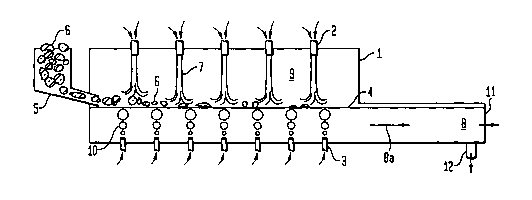
As shown in Fig. 1, a premelter or the rapid melting zone of a glass melter
furnace 1 preferably contains roof mounted oxy-fuel burners 2. Gas bubbler
tubes 3
CA 02446251 2003-10-31
WO 02/090271 PCT/US02/13294
or "bubblers" are positioned in the floor of the furnace 1. Bubbles 10 of
fluid, such as
gas, water or steam, emanate from the bubblers 3 into the glass bath 8, that
is, the
bulk glass, within the premelter or melting zone. The bubbles 10 aid in mixing
the
glass bath 8, so as to come into contact with and submerse raw or unmelted
glass
batch materials 6 floating on the surface of the glass bath, or glass line 4
to promote
melting. Flames 7 from the combustion of oxygen and fuel (such as natural gas
or
oil) by means of the oxy-fuel burners 2 traverse the furnace combustion
chamber 9 to
impinge on raw, unmelted glass batch materials 6 proximate to the glass line
4.
As shown in Fig. 2, raw, unmelted glass batch materials 6 contained in a raw
material hopper 5 are charged to the premelter or the rapid melting zone of a
glass
furnace 1 substantially at the glass line 4. The materials are rapidly melted
by the
combination of a) the flames 7 from the combustion of oxygen and fuel (such as
natural gas or oil) within the furnace combustion chamber 9, from the roof
mounted
oxy-fuel burners 2, impinging on the unmelted materials 6 proximate to the
glass line
4, and b) the action of the bubbles 10 of fluid, such as gas, water or steam,
from the
bubbler tubes 3 in the floor of the furnace 1, which bring melted glass 8 into
mixing
contact with the unmelted materials 6. The glass bath 8 flows downstream (as
shown
by the arrow 8a) of the charger to a glass exit 11 in the case of a premelter,
or to a
glass exit 12 in the case of a glass melter.
It is within the scope of the present invention to provide multiple roof
mounted burners within the rapid glass melting apparatus, with more than one
burner
having bubblers associated with the burner, and the bubbling of gases
occurring
proximate to the multiple areas where the flames of the associated burners
impinge on
or near the surface of the batch material.
The melted glass bath may flow downstream through to the fining zone of the
glass welter furnace, or to a conventional glass furnace or glass refining
apparatus
from the premelter. According to the method of the present invention, it is
preferred
that the bulk glass in the glass bath that is received by the furnace for
fining, contain
less than about 50% to about 80% of the seeds and blisters typically received
in
conventional furnaces. This results in higher quality glass being produced.
Although
contrasted from the glass melt, the amount of seeds that would typically be
accepted
in a glass container product is on the order of about 27 seeds per ounce of
glass; less
11
CA 02446251 2003-10-31
WO 02/090271 PCT/US02/13294
would be found acceptable in a float glass product.
In one embodiment of the present invention, a rapid premelter having roof
mounted oxy-fuel burners in association with bubblers positioned in the floor
of the
pre-welter may be removably positioned to feed molten glass into a
conventional
glass welter as a "charger" or into a glass refining apparatus. The apparatus
may be
mounted on wheels, rails, track, or an air flow pad, so as to be movable into
engagement with and disengagement from the glass welter or refining apparatus.
The
pre-welter may be one of a plurality of such apparatus, feeding into a common
to channel connected to the glass welter or refining apparatus. Such a
configuration
would reduce or eliminate glass furnace downtime that would otherwise result
from
maintenance, repair or replacement of a premelter feeding the furnace.
Description of elements in Figs. 1 and 2:
Item 1 furnace, welter or premelter
Item 2 oxy-fuel burners
Item 3 bubbler tubes
Item 4 glass line (surface or top of glass in welter)
Item 5 raw material hopper
Item 6 raw or urunelted glass batch materials
Item 7 flames from oxy-fuel burners
Item 8 the glass bath
Item 8a the glass bath flow
Item 9 the furnace combustion chamber
Item 10 bubbles of gas andlor water and/or steam passed through bubblers
Item 11 glass exit of premelter
Item 12 glass exit of welter.
It should be appreciated that the present invention is not limited to the
3o specific embodiments described above, but includes variations,
modifications and
equivalent embodiments defined by the following claims.
12