Language selection

Search

Patent 2446644 Summary

Third-party information liability

Some of the information on this Web page has been provided by external sources. The Government of Canada is not responsible for the accuracy, reliability or currency of the information supplied by external sources. Users wishing to rely upon this information should consult directly with the source of the information. Content provided by external sources is not subject to official languages, privacy and accessibility requirements.

Claims and Abstract availability

Any discrepancies in the text and image of the Claims and Abstract are due to differing posting times. Text of the Claims and Abstract are posted:

  • At the time the application is open to public inspection;
  • At the time of issue of the patent (grant).
(12) Patent: (11) CA 2446644
(54) English Title: METHOD FOR REPAIRING ELECTROLYSIS CATHODES
(54) French Title: PROCEDE DE REPARATION DE CATHODES D'ELECTROLYSE
Status: Expired and beyond the Period of Reversal
Bibliographic Data
(51) International Patent Classification (IPC):
  • C25C 07/02 (2006.01)
(72) Inventors :
  • BROEHAN, HEINRICH (Germany)
  • HEYFELDER, GUENTER (Germany)
  • KROLL, GUENTER (Germany)
  • LEMKE, JOACHIM (Germany)
  • MARR, DIETER (Germany)
  • HANSEN, UWE-JENS (Germany)
  • LANDAU, MICHAEL (Germany)
(73) Owners :
  • NORDDEUTSCHE AFFINERIE AKTIENGESELLSCHAFT
(71) Applicants :
  • NORDDEUTSCHE AFFINERIE AKTIENGESELLSCHAFT (Germany)
(74) Agent: SMART & BIGGAR LP
(74) Associate agent:
(45) Issued: 2009-04-14
(86) PCT Filing Date: 2002-03-14
(87) Open to Public Inspection: 2002-11-14
Examination requested: 2006-11-03
Availability of licence: N/A
Dedicated to the Public: N/A
(25) Language of filing: English

Patent Cooperation Treaty (PCT): Yes
(86) PCT Filing Number: PCT/DE2002/000890
(87) International Publication Number: DE2002000890
(85) National Entry: 2003-11-07

(30) Application Priority Data:
Application No. Country/Territory Date
101 22 326.9 (Germany) 2001-05-08

Abstracts

English Abstract


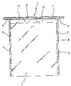
The invention relates to a method for repairing electrolysis cathodes that,
together with anodes in a galvanic bath provided for carrying out a galvanic
electrolysis, are connected to a power source. The electrolysis cathodes are
comprised of a crossbeam, which is arranged above the galvanic bath for being
electrically connected to at least one supply bar, and of a metal cathode that
projects into the galvanic bath. At least one portion of the cathode sheet
metal is detached from the crossbeam by subjecting it to thermal action in an
essentially uniform manner in the area of a first cutting edge. In order to
provide a second cutting edge, a replacement sheet metal is cut to size at
least in the area of an extension, which can be turned towards the crossbeam,
by subjecting it to thermal action in an essentially uniform manner. The
replacement sheet metal is welded to the first cutting edge in the area of the
second cutting edge by subjecting the sheet metal to thermal action in an
essentially uniform manner.


French Abstract

La présente invention concerne un procédé permettant la réparation de cathodes d'électrolyse qui, avec des anodes, sont connectées à une source de courant dans un bain galvanique pour permettre la mise en oeuvre d'une électrolyse galvanique. Les cathodes d'électrolyse sont constituées d'un support transversal disposé au-dessus du bain galvanique pour permettre le contact électrique avec au moins une barre de connexion, et d'une cathode métallique dépassant dans le bain galvanique. Au moins une partie de la plaque cathodique est séparée du support transversal grâce à l'application d'une contrainte thermique sensiblement uniforme au niveau d'une première arête. Pour permettre la formation d'une seconde arête, une lame de remplacement est découpée au moins au niveau d'un élargissement qui peut être dirigé vers le support transversal, grâce à l'application d'une contrainte thermique sensiblement uniforme. La plaque de remplacement est soudée à la première arête grâce à l'application d'une contrainte thermique sensiblement uniforme au niveau de la seconde arête.

Claims

Note: Claims are shown in the official language in which they were submitted.


Claims
1. Method for repairing electrolysis cathodes, which are connected to a power
source together with anodes provided in a galvanic bath for carrying out a
galvanic electrolysis, said electrolysis cathodes comprising a cross beam that
is
arranged above the galvanic bath for being electrically connected to a least
one
supply bar, and cathode plate that extends into the galvanic bath,
characterized in
that least a portion of the cathode sheet metal is cut off from the cross beam
in the
area of a first cut edge of the cross beam (2) by subjecting it to thermal
action in
an essentially uniform manner; in that replacement sheet metal is cut to size
at
least along its dimension that can be turned towards the cross beam (2), by
subjecting it to thermal action in an essentially uniform manner so as to
provide a
second cut edge; and in that the replacement sheet metal is welded to the
first cut
edge in the area of the second cut edge by subjecting it to thermal action in
an
essentially uniform manner.
2. Method as defined in Claim 1, characterized in that the used cathode sheet
metal
(3) is separated from the cross beam (2) in the area of the first cut in edge
by
using a laser.
3 Method as defined in Claim 1 or Claimed 2, characterized in that the
replacement
sheet metal is cut to size with a laser, at least along its dimension that can
be
turned towards the cross beam, so as to prepare the second cut edge.
8

4. Method as defined in one of the Claims 1 to 3, characterized in that the
second
cut edge is welded to the first cut edge by using a laser.
5. Method as defined in one of the Claims 1 to 4, characterized in that the
structural
elements that are to be joined to one another are clamped prior to the welding
process.
6. Method as defined in one of the Claims 1 to 5, characterized in that prior
to the
welding process the structural elements that are to be joined to one another
are
oriented so as to be parallel to one another.
7. Method as defined in one of the Claims 1 to 6, characterized in that the
first cut
edge is clamped relative to the second cut edge during the welding process.
8. Method as defined in one of the Claims 1 to 7, characterized in that in the
area of
the welded seam, a cover is produced between the welded seam and the weld root
9. Method as defined in one of the Claims 1 to 8, characterized in that the
recesses
in the cathode sheet metal (3) for attaching the insulating rails (6, 7) are
produced
with the help of a laser.
10. Method as defined in one of the Claims 1 to 9, characterized in that
plates of
stainless steel are used as the cathode sheet metal (3).
11. Method as defined in one of the Claims 1 to 10, characterized in that
copper
plates are used as the anodes.
9

12. Method as defined in one of the Claims 1 to 11, characterized in that a
source of
DC power is used as the power source.
10

Description

Note: Descriptions are shown in the official language in which they were submitted.


CA 02446644 2003-11-07
' WO 02/090622 PCT/DE02/00890
Method for Repairing Electrolysis Cathodes
The present invention relates to a method for repairing electrolysis cathodes,
which are
connected to a power source together with anodes provided in a galvanic bath
for carrying
out galvanic electrolysis,. The electrolysis cathodes comprise a cross beam
that is arranged
above the galvanic bath for being electrically connected to a least one supply
bar, and a
metal cathode plate that extends into the galvanic bath.
Cathodes of this type can be used, for example, when producing electrolytic
copper, when
the anode plates are of impure cast copper plates that are dissolved in the
electrolyte during
electrolysis, the copper from them being then deposited on the stainless steel
plates as pure
copper. The impurities accumulate within the electrolysis bath, mainly in the
form of
bottom sludge. A typical procedure is that approximately once each week the
cathodes are
removed from the galvanic bath, the copper is removed from them, and they are
then
reinstalled. After approximately three weeks, the copper anodes have dissolved
to the
point that they have to be replaced. The cross beam of the cathodes typically
consists of a
copper-plated supporting rod so as to ensure a low transitional resistance
between the cross
beam and the conductor rail.
Because of the weekly, mechanical cleaning of the cathodes and because of the
process
conditions that act on the cathodes, these are subjected to wear. This wear
leads to the fact
that when the copper is being removed from the stainless steel plates, the
cathode will be
deformed. This deformation of the cathodes results in degraded efficiency
during
electrolysis and thus slows down the rate at which the copper is deposited on
the cathodes.
1

CA 02446644 2003-11-07
WO 02/090622 PCT/DE02/00890
Once a certain degree of deformation has been reached, it is no longer
possible to use the
cathodes for electrolysis. When galvanic electrolysis is used on an industrial
scale to
deposit copper, many thousands of cathodes are used at the same time. The
useful life of
the cathodes is thus an important cost factor when producing copper.
Since the cross beam for the cathodes exhibits almost no signs of wear,
attempts were made
to cut off the used stainless steel plate and weld new stainless steel plate
onto the cross
beam. When this was done, however, it turned out that using the procedure that
was tried,
considerable stresses were generated in the stainless steel sheet metal and
this led to the
fact that cathodes repaired in this way warped very rapidly in the hot
electrolysis bath. For
this reason, known repair procedures have been unsatisfactory and this has led
to the fact
that once the cathode sheet metal has reached a degree of deformation that is
no longer
acceptable, the complete cathode together with the cross beam must be replaced
by a new
cathode, and the old cathode must be scrapped.
For this reason, it is the objective of the present invention to describe a
method of the type
described in the introduction hereto so that electrolysis cathodes that had
been repaired
have a sufficiently long service life.
According to the present invention, this objective has been achieved in that
at least a
portion of the cathode plate is cut off from the cross beam in the area of a
first cut edge by
subjecting it to thermal action in an is essentially uniform manner; in that
replacement
sheet metal is cut to size at least in the area of its dimension that can be
turned towards the
cross beam, by subjecting it to thermal action in an essentially uniform
manner so as to
provide a second cut edge; and in that the replacement sheet metal is welded
to the first cut
2

CA 02446644 2003-11-07
WO 02/090622 PCT/DE02/00890
edge in the area of the second cut edge by subjecting it to thermal action in
an essentially
uniform manner.
By separating the used cathode sheet metal from of the remaining part of the
cathode by an
essentially uniform thermal action, only a very small amount of thermal load
acts on the
remaining part. Furthermore, the first cut edge that has been prepared can be
subjected to a
subsequent welding process without any additional processing. Any extra
thermal and
mechanical stresses that could occur during an additional processing step are
thus avoided.
The same advantages are achieve by cutting with the help of an essentially
uniform thermal
action in the area of the replacement sheet metal.
Finally, carrying out the welding procedure by an essentially uniform thermal
action leads
to very small amount of thermal stress, and the residual thermal stress occurs
with a very
high level of uniformity. Practical test show that electrolysis cathodes
repaired in this way
display almost the same resistance to deformation as new cathodes. Compared to
a total
replacement of the cathode, it is thus possible to a achieve a clear cost
advantage by doing
this.
A very high level of uniformity can be achieved when completing the separation
procedure
in that the used cathode sheet metal is separated from the cross beam in the
area of the first
cut edge by using a laser.
As far as assembly of the replacement sheet metal is concerned, it is
advantageous if the
first replacement sheet metal be cut to size with a laser, at least along its
dimension that can
be turned to face the cross beam, so as to produce the second cut edge.

CA 02446644 2003-11-07
WO 02/090622 PCT/DE02/00890
Minimal thermal warping can also be ensured if the second cut edge is welded
to the first
cut edge by using a laser.
In order to produce a very uniform weld, it has been found to be advantageous
if the
structural elements that are to be joined are clamped prior to the welding
process.
Similarly, a uniform weld and uniform heat dispersion can be facilitated if
the structural
elements that are to be joined to each other are oriented so as to be parallel
relative to each
other, before the welding process is carried out.
In order to ensure low additional electrical resistance in the area of the
weld, it is suggested
that the first cut edge the braced relative to the second cut edge during the
welding process.
Similarly, a reduction of cross section in the area of the weld, and the
resulting increase of
electrical resistance, can be avoided in that a covering between the weld seam
and the weld
root be produced in the area of the weld seam.
In order to ensure a long service life for the electrolysis cathodes, it is
also useful if
recesses for securing insulating rails are made in the cathode sheet metal
with the help of a
laser.
Embodiments of the present invention are shown in the drawings appended
hereto. These
drawings show the following:
Figure 1: a side view of an electrolysis cathode;
Figure 2: a side view as seen in the direction II indicated in Figure l;
Figure 3: an enlarged view of the detail III indicated in Figure 2;
4

CA 02446644 2003-11-07
WO 02/090622 PCT/DE02/00890
Figure 4: an enlarged view of one end area of a cross beam of the electrolysis
cathode;
Figure 5: a perspective view of the electrolysis cathode shown in Figure 1;
Figure 6: a cross section through an electrolysis cathode that is clamped in
the area of a
welding device and which is to be provided with new cathode sheet metal;
Figure 7: an enlarged cross sectional view in the area of the weld seam.
Figure 1 shows an electrolysis cathode (1) that has a cross beam (2) and
cathode plate (3).
The cathode plate (3) is of stainless steel and is welded to the cross beam
(2). It is
preferred that the cross beam (2) be a copper-coated supporting rod.
The cathode plate (3) is provided with insulating rails (6, 7) along its side
edges (4, 5).
These insulating rails (6, 7) can be in the form of plastic rails. In order to
secure the
insulating rails (6, 7), the cathode plate (3) incorporates recesses through
which attachment
elements extend. End segments (8, 9) of the cross beam (2) extend beyond the
insulating
rails (6, 7), so that the electrolysis cathode (1) can be suspended in an
electrolysis bath (not
shown herein).
Figure 1 shows an electrolysis cathode (1) from which original cathode sheet
metal (3) has
been separated and replaced by new sheet metal, so that a welded seam (10)
extends from
one side edge (4) to the other side edge (5). In order to simplify
transportation, the
electrolysis cathode (1) incorporates two recesses (11, 12) beneath the cross
beam (2),
through which the holding devices of a transportation apparatus can be passed.
Positioning the welded seam ( 10) slightly below the recesses ( 11, 12)
entails the advantage
that the welding process can be completed in one operation, without having to
reposition
5

CA 02446644 2003-11-07
WO 02/090622 PCT/DE02/00890
the welding electrodes. However, in order to provide for the greatest possible
space
between the welded seam (10) and the surface of the electrolysis bath, thought
was also
given to having the weld seam extend at the level of lower limits of the
recesses (11, 12).
Admittedly, if this is done, the welding electrodes must be repositioned three
times during
the welding process, but if this is done the distance between the welded seam
and the
surface of the electrolyte when it has been immersed in the electrolysis bath
can be
increased. Furthermore, the actual length of the welded seam is reduced by the
extent of
the recesses ( 11, 12).
The side view in Figure 2 shows that the cross beam (2) can be configured as
an I-beam. It
can also be seen that the insulating rails (6, 7) essentially cover the whole
area of the side
edges (4, 5).
From the enlarged view shown at Figure 3, it can be seen that the cathode
plate (3) is
connected to the cross beam (2) through welded seams (13).
Figure 4 is a cross section through one of the end segments (8, 9). It can be
seen that a
lower area of the end segments (8, 9) is configured as a taper (14). This
configuration
ensures that when the end segments (8, 9) rests on a conductor rail (15),
there is greater
contact pressure per unit area and thus less transitional resistance to
electric current.
Figure 5 is a perspective view that illustrates the structure of the
electrolysis cathode (1).
The rugged configuration of the cross beam (2) as well as the lateral
extension of the end
segments (8, 9) of the cross beam (2) can be seen in particular.
6

CA 02446644 2003-11-07
WO 02/090622 PCT/DE02/00890
Figure 6 shows the arrangement of the electrolysis cathode (1) in the area of
a welder (25)
that is used to produce the welded seam (10). Both the new cathode sheet metal
(3) and the
cross beam (2) with the residual portion (16) of the original cathode sheet
metal (3) are
held in place by clamping devices (17, 18) and acted upon by clamping forces
(19, 20, 21,
22). A transverse force (24) is generated by means of a feed device (23) that
guides the
new cathode sheet metal (3) and the segment (16) of the old sheet metal
together with a
specific amount of contact pressure on their surfaces. In this state the
welder (25) is moved
along the welded seam (10) that is to be produced.
The structure of the welded seam (10) is shown in detail in Figure 7. The
welded seam
(10) has a seam root (26) and a seam cover (27) that extend along opposite
sides of the
electrolysis cathode (1). The seam root (26) and the seam cover (27) are
joined to one
another by a weld (28) that runs between a first cut edge (29) of the segment
(16) of
residual sheet metal and the second cut edge (30) of the new cathode sheet
metal (3).
7

Representative Drawing
A single figure which represents the drawing illustrating the invention.
Administrative Status

2024-08-01:As part of the Next Generation Patents (NGP) transition, the Canadian Patents Database (CPD) now contains a more detailed Event History, which replicates the Event Log of our new back-office solution.

Please note that "Inactive:" events refers to events no longer in use in our new back-office solution.

For a clearer understanding of the status of the application/patent presented on this page, the site Disclaimer , as well as the definitions for Patent , Event History , Maintenance Fee  and Payment History  should be consulted.

Event History

Description Date
Time Limit for Reversal Expired 2022-03-01
Letter Sent 2021-03-15
Letter Sent 2021-03-01
Letter Sent 2020-08-31
Inactive: COVID 19 - Deadline extended 2020-08-19
Inactive: COVID 19 - Deadline extended 2020-08-06
Inactive: COVID 19 - Deadline extended 2020-07-16
Inactive: COVID 19 - Deadline extended 2020-07-02
Inactive: COVID 19 - Deadline extended 2020-06-10
Inactive: COVID 19 - Deadline extended 2020-05-28
Inactive: COVID 19 - Deadline extended 2020-05-14
Inactive: COVID 19 - Deadline extended 2020-04-28
Inactive: COVID 19 - Deadline extended 2020-03-29
Common Representative Appointed 2019-10-30
Change of Address or Method of Correspondence Request Received 2018-03-28
Grant by Issuance 2009-04-14
Inactive: Cover page published 2009-04-13
Inactive: Final fee received 2009-02-02
Pre-grant 2009-02-02
Letter Sent 2009-01-09
Notice of Allowance is Issued 2009-01-09
Inactive: Approved for allowance (AFA) 2008-09-15
Letter Sent 2006-11-30
All Requirements for Examination Determined Compliant 2006-11-03
Request for Examination Requirements Determined Compliant 2006-11-03
Request for Examination Received 2006-11-03
Letter Sent 2004-01-29
Inactive: Cover page published 2004-01-19
Inactive: Notice - National entry - No RFE 2004-01-15
Inactive: First IPC assigned 2004-01-15
Inactive: Single transfer 2003-12-15
Application Received - PCT 2003-11-26
National Entry Requirements Determined Compliant 2003-11-07
Application Published (Open to Public Inspection) 2002-11-14

Abandonment History

There is no abandonment history.

Maintenance Fee

The last payment was received on 2008-12-30

Note : If the full payment has not been received on or before the date indicated, a further fee may be required which may be one of the following

  • the reinstatement fee;
  • the late payment fee; or
  • additional fee to reverse deemed expiry.

Patent fees are adjusted on the 1st of January every year. The amounts above are the current amounts if received by December 31 of the current year.
Please refer to the CIPO Patent Fees web page to see all current fee amounts.

Owners on Record

Note: Records showing the ownership history in alphabetical order.

Current Owners on Record
NORDDEUTSCHE AFFINERIE AKTIENGESELLSCHAFT
Past Owners on Record
DIETER MARR
GUENTER HEYFELDER
GUENTER KROLL
HEINRICH BROEHAN
JOACHIM LEMKE
MICHAEL LANDAU
UWE-JENS HANSEN
Past Owners that do not appear in the "Owners on Record" listing will appear in other documentation within the application.
Documents

To view selected files, please enter reCAPTCHA code :


To view images, click a link in the Document Description column. To download the documents, select one or more checkboxes in the first column and then click the "Download Selected in PDF format (Zip Archive)" or the "Download Selected as Single PDF" button.

List of published and non-published patent-specific documents on the CPD .

If you have any difficulty accessing content, you can call the Client Service Centre at 1-866-997-1936 or send them an e-mail at CIPO Client Service Centre.


Document
Description 
Date
(yyyy-mm-dd) 
Number of pages   Size of Image (KB) 
Description 2003-11-06 7 275
Claims 2003-11-06 3 74
Drawings 2003-11-06 4 55
Abstract 2003-11-06 1 26
Representative drawing 2008-10-27 1 6
Reminder of maintenance fee due 2004-01-14 1 107
Notice of National Entry 2004-01-14 1 190
Courtesy - Certificate of registration (related document(s)) 2004-01-28 1 107
Reminder - Request for Examination 2006-11-14 1 118
Acknowledgement of Request for Examination 2006-11-29 1 178
Commissioner's Notice - Application Found Allowable 2009-01-08 1 163
Commissioner's Notice - Maintenance Fee for a Patent Not Paid 2020-10-18 1 549
Courtesy - Patent Term Deemed Expired 2021-03-28 1 540
Commissioner's Notice - Maintenance Fee for a Patent Not Paid 2021-04-26 1 536
PCT 2003-11-06 6 245
Correspondence 2009-02-01 1 38