Note: Descriptions are shown in the official language in which they were submitted.
CA 02446757 2003-10-30
WO 02/102681 PCT/US02/16488
TITLE
SINGLE-PIECE FOLD-TO-SHAPE PROTECTIVE DEVICE
BACKGROUND
Field Of The Invent
This patent relates to a device for protecting items
such as household appliances from damage during shipping
and handling. More specifically, this patent relates to
a protective device formed from a single piece of
laminated paperboard that can be folded into a hollow
tubular shape when ready to be used.
Description Of The Related Ar
Protective devices consisting essentially of paper
tubes are used to support and cushion the corners of
large appliances (such as washers, dryers and the like)
during storage and transport. Conventional protective
devices, such as the highly successful Sonopost~
protective device, typically are formed from two or more
plies of convolutely wound laminated paperboard formed
into a protective shape on a mandrel and then dried into
the finished shaped tubular form.
A disadvantage such of conventional convolutely
wound protective devices is that they can only be made
from a single type of paperboard, since the paperboard is
fed from a single roll onto the mandrel. This
disadvantage was addressed in Qiu U.S. Patent No.
6,186,329, commonly owned with this invention, which
describes a support post made of multiple sheets of
CA 02446757 2003-10-30
WO 02/102681 PCT/US02/16488
2
paperboard joined together edge-to-edge to form a roll.
The roll is then convolutely wound onto a mandrel,
formed, and dried to produce a hollow tubular protective
post. The protective post can be made from more than one
type of paper, or from paper having different
orientations, or from cross-laminated paper.
However, the finished product is a hollow tubular
protective that takes up as much room during shipping and
storing as conventional convolutely wound protective
devices. There exists a need for a protective device
that can made from more than one type of paper, or from
paper having different orientations, or from cross-
laminated paper, but can be shipped and stored in a
substantially flat configuration and then folded to shape
when ready to use.
Thus, it is an object of the present invention to
provide a single piece protective post that can be
stacked or nested in an unfolded position and then folded
into the desired shape when ready for use.
Another object of the present invention is to
provide a single piece protective post that can be made
from more than one type of paper.
Yet another object of the present invention is to
provide a protective post that can be made from paper
layered in different orientations.
Further and additional objects will appear from the
description, accompanying drawings, and appended claims.
CA 02446757 2003-10-30
WO 02/102681 PCT/US02/16488
3
SUMMARY OF THE INVENTION
The present invention is a single piece protective
device that can be stacked or nested in an unfolded
position and then folded into the desired shape when
ready for use.
The device is made from a substantially rectangular sheet
of laminated paperboard. The sheet comprises a hinged
area running longitudinally from top to the bottom, an
outer wall portion extending from the hinged area and
terminating in a connecting portion, and an inner wall
portion extending from the hinged area away from the
outer wall portion and terminating in another connecting
portion.
Preferably, the hinged area comprises a plurality of
longitudinal creases. Each crease can extend the entire
height of the sheet or less than the entire height of the
sheet. In the latter instance, the creases may be
staggered. The hinged area may comprise smooth,
uncreased horizontal sections disposed between the
staggered creases.
The sheet is made of multiple plies of material
laminated together. The plies can be made from different
types of paperboard, may be oriented in different
directions, or may be cross-laminated to achieve desired
structural properties.
The protective device may be L-shaped to protect the
corner of a packaged article or I-shaped to protect the
side walls of an article. In either case the unfolded
CA 02446757 2003-10-30
WO 02/102681 PCT/US02/16488
4
sheets are nestable for efficient storage and shipping.
When folded to form the finished protective device,
the connecting portions may form a snap fit.
Alternatively, the connecting portions may be glued,
stitched or stapled together. The walls may have
integrally formed beads or grooves for added strength.
CA 02446757 2003-10-30
THE DRAWINGS
Figure 1 is a top plan view of a protective post
according to the present invention in an unfolded position.
5 Figure 2 is a top plan view of the protective post of
Figure 1 after it has been folded into shape.
Figure 3 is a perspective view of the protective post of
Figure 2.
Figure 4 is a top plan view of a second embodiment of a
protective post according to the present invention in an
unfolded position.
Figure 5 is top plan view of a third embodiment of a
protective post according to the present invention in an
unfolded position.
Figure 6 is a top plan view of the protective post of
Figure 5 after it has been folded into shape.
Figure 7 is a top plan view of a fourth embodiment of a
protective post according to the present invention in an
unfolded position.
Figure 8 is a top plan view of the protective post of
Figure 7 after it has been folded into shape.
Figure 9 is a top plan view of a fifth embodiment of a
protective post according to the present invention in an
unfolded position.
Figure 10 is a top plan view of the protective post of
Figure 9 after it has been folded into shape.
Figure 11 is a perspective view of a protective post
according to the present invention with staggered creases
along the hinged area.
CA 02446757 2003-10-30
5a
Figure 12 is a perspective view of a protective post
according to the present invention having a hinged area having
uncreased horizontal sections disposed between creases.
Figure 13 is a perspective view of a protective post
according to the present invention having score lines along
the hinged area.
Figure 14 is a perspective view of a protective post
according to the present invention having staggered score
lines along the hinged area.
Figure 15 is a perspective view of a protective post
according to the present invention having a hinged area having
uncreased horizontal sections disposed between score lines.
CA 02446757 2003-10-30
WO 02/102681 PCT/US02/16488
6
DETAILED DESCRIPTION OF THE INVENTION
Turning to the drawings, there is shown in Figure 1
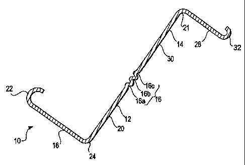
one embodiment of the present invention, a protective
device 10 used for cushioning and protecting packaged
articles such as large appliances. The protective device
is placed between the product and the packaging walls
to provide protection from both axial (vertical) and
transverse (horizontal) forces.
In the embodiment shown in Figures 1-3, the
10 protective device 10 comprises an outer wall portion 12
and an inner wall portion 14 connected by a hinged area
16. As shown in Figure 2, one or both of the wall
portions 12, 14 can be rotated with respect to the hinged
area 16 to form the hollow L-shaped tube 10 shown in
Figures 2 and 3.
The outer wall portion 12 comprises first and second
legs 18, 20 connected at an outer wall apex 24 and
forming a substantially right angle. The first leg 18
terminates in a hook or connecting portion 22. The
second leg 20 terminates at the hinged area 16.
The inner wall portion 14 comprises first and second
legs 28, 30 connected along an inner corner 21 and
forming a substantially right angle. The inner legs 28,
correspond to the first and second outer legs 18, 20
25 such that, if the inner wall portion 14 is rotated
counterclockwise (viewed from above) around the hinged
area 16 to form the tubular corner post 10 of Figure 2,
the first inner leg 28 is parallel to the first outer leg
CA 02446757 2003-10-30
WO 02/102681 PCT/US02/16488
7
18, and the second inner leg 30 is parallel to the second
outer leg 20.
Like the first inner leg 18, the first outer leg 28
terminates in a hook or connecting portion 32. The
connecting portions may be curved, as shown in the
figures, squared, or any other suitable configuration
such that, when the wall portions 12, 14 are brought
together, the connecting portions 22, 32 cooperate to
form a close fit. If the connecting portions are curved
as shown in the figures, the outer connecting portion 22
may define an arc slightly greater than 180 degrees so
that the end portions snap together, although this will
have an adverse effect on nestability.
Instead of, or in addition to, the snap fit, the
connecting portions 22, 32 may be joined by adhesive,
staples, stitches or any other suitable means to form the
finished protective device 10 shown in Figure 3. Because
the connecting portions 22, 32 overlap as shown in
Figures 2 and 3, that area of the protective device is
stronger than the same area in a conventional wound
protective device.
Preferably, the hinged area 16 comprises three
longitudinal creases 16a, 16b, 16c running longitudinally
from top to bottom as shown in Figure 1, although any
suitable number of creases may be used. For example, the
hinged area 16 may be made with two creases, each crease
defining a ninety-degree angle when the device is folded.
When the walls 12, 14 are brought together into
CA 02446757 2003-10-30
8
alignment, the creased areas 16a, 16b, 16c form a 180 degree
curve, as shown in Figures 2 and 3. It is important that this
curve be as smooth as possible to maintain the integrity of
the protective device, especially with regard to resistance to
axial and transverse forces.
The width and depth of the creases 16a, 16b, 16c and the
distance between the creases 16a, 16b, 16c can be varied
depending on the desired properties, such as bending
resistance, and the desired distance between the walls 12, 14
in the finished device 10. For example, three or four creases
spaced 1/4 to 3/8 inches apart can provide a protective device
10 in which the outer and inner walls are one-half to one inch
apart.
The creases may run the entire vertical length of the
protective device or less than the entire length. In the
latter case, the creases may staggered, as shown in Figure 11.
The staggered creases may overlap (Figure 11) or there may be
little horizontal areas that are not creased (Figure 12).
Horizontal areas that are not creased will strengthen the
protective device 10 by leaving the paperboard fibers in those
areas unbroken. Thus, when lifting or carrying the unfolded
protective device 10, the non-creased areas will tend to
support the device 10 and prevent premature bending of the
device 10 along the hinged area 16.
Preferably, the paperboard fibers run substantially
longitudinally (vertically). This makes it is easier to bend
the device 10 along the hinged area 16. The less
CA 02446757 2003-10-30
9
the fibers are oriented longitudinally, the harder the device
will be to bend, and the more necessary it becomes to crease
or score the hinged area 16.
Creasing the hinged area 16 will result in slight
indentations on the creased side of the wall. Depending on
the depth of the indentations and the tool used to make the
indentations, there may be slight raised areas on the opposite
side.
Instead of creases, the hinged area 16 may be slit scored
as shown in Figures 13-15. Scoring may be done on the
exterior side of the hinged area, the interior side, or both.
In the alternative embodiment shown in Figure 4, instead
of creases or score lines, the hinged area comprises a single
V-shaped bend 46. The bend 46 is made during the process of
forming the unfolded protective device 40 summarized below.
Like the Figure 1 embodiment, the protective device of Figure
4 comprises an outer wall portion 42 and an inner wall portion
44 that fold together to form a substantially L-shaped post.
Also like the Figure 1 embodiment, each wall portion 42, 44
terminates in a hook or connecting portion 52, 62. When the
wall portions 42, 44 are brought together, the end portions
52, 62 cooperate to form a close fit. The end portions may be
configured such that they form a snap fit, or may be joined by
adhesive, staples, stitches or any other suitable means to
form the finished protective device.
Preferably, the hinged area 46 comprises two mirror-
CA 02446757 2003-10-30
WO 02/102681 PCT/US02/16488
image opposing curved areas 46a, 46b as shown in Figure
4. Each curved area 46a, 46b is preformed in linear
fashion by being pressed into a shallow mandrel to define
an arc of about ninety degrees. When the walls 42, 44
5 are brought into alignment, the curved areas 46a, 46b
form a relatively smooth 180 degree curve.
The protective device may be made in the following
manner. First, using a linear type drawing apparatus, a
substantially rectangular sheet is made comprising
10 multiple plies of paper or paperboard laminated together.
The plies may be made from different types of paperboard
and/or may be oriented in different directions. Next,
while the laminate is still wet, the sheet is formed into
a semi-profiled nestable type shape as shown in Figures 1
and 4 using a forming apparatus. Rollers or bars on
either side of the linear drawing apparatus can be used
to shape the hooks or connecting portions. For the
creased structure shown in Figure 1, an additional
creasing step may be required. If the hinged area is
scored, a scoring step is required. After drying, the
semi-profiled nestable type structure is shipped to a
customer who then folds the device and joins the
connecting portions before use.
Conventional wound tubular protective devices are
made by winding a continuous roll of paperboard around an
L-shaped mandrel. Forming mandrels under hydraulic
pressure then press the wound paper against the h-shaped
mandrel while the laminate is drying. Because a
CA 02446757 2003-10-30
WO 02/102681 PCT/US02/16488
11
continuous roll of paperboard is used, the finished
product is made of only one type of paper.
By contrast, the present invention is made from
multiple plies of paperboard stacked and laminated
together. The invention can be made using more than one
type of ply and/or different ply sizes and ply
orientations to suit individual applications and
conditions. If desired, the plies may be cross-laminated
(i.e. the lamination. applied in different directions).
Figures 5 and 6 show another embodiment of the
present invention wherein the folded protective device 70
is linear or I-shaped to fit flush between planar
surfaces, such as the side of an appliance and the inside
wall of a package or carton. The device 70 is best used
to cushion and protect a packaged product by placing it
between the product and the inside wall of the package
about halfway between adjoining corners.
The I-shaped protective device 70 comprises a first
wall portion 72 and a second wall portion 74 connected by
a hinged area 76. In the embodiment shown in Figures 5
and 6, the hinged area 76 comprises three creases 76a,
76b, 76c, but any suitable number of creases and/or
scores may be used.
Like the previous embodiments, each wall portion 72,
74 terminates in a hook or connecting portion 82, 84.
When the wall portions 72, 74 are brought together, the
connecting portions 82, 84 cooperate to form a close fit.
The connecting portions may be joined by adhesive,
CA 02446757 2003-10-30
WO 02/102681 PCT/US02/16488
12
staples, stitches or any other suitable means.
Figures 7 and 8 show another embodiment of the
present invention, one that folds to become a
substantially L-shaped protective device. The protective
device 90 comprises an outer wall portion 92 and an inner
wall portion 14 connected by a hinged area 96. One or
both of the wall portions 92, 94 can be rotated with
respect to the hinged area 96 to form the hollow L-shaped
tube 90 shown in Figure 8.
Unlike the embodiment shown in Figure l, this
embodiment has a second hinged area located at the outer
wall apex 104. Prior to folding, the outer wall portion
92 is substantially linear, not L-shaped, and comprises
first and second legs 98, 100 connected at the hinged
outer wall apex 104. The first leg 98 terminates in a
hook or connecting portion 102. The second leg 100
terminates at the hinged area 96.
The inner wall portion 94 is substantially L-shaped
and comprises first and second legs 108, 110 connected
along an inner corner 101. The first leg 108 extends
away from the inner corner 101 and terminates in a hook
or connecting portion 112. The second leg 110 extends
away from the inner corner 101 and terminates at the
hinged area 96.
To form the finished device 90, the first and second
outer wall legs 98, 100 are brought into perpendicular
alignment by rotating the first leg 98 clockwise (when
viewed from the top) about the hinged apex area 104. The
CA 02446757 2003-10-30
WO 02/102681 PCT/US02/16488
13
inner wall portion 94 is rotated counterclockwise around
the hinged area 96 until the first inner leg 108 is
parallel to the first outer leg 98 and the second inner
leg 110 is parallel to the second outer leg 100. The
result is the tubular corner post 90 of Figure 8. The
connecting portions 102, 112 cooperate to form a close
fit that may be glued, stapled, stitched or otherwise
joined.
Figures 9 and 10 show still another embodiment of a
single piece fold-to-shape protective device 120 made
according to the present invention. The protective
device 120 comprises an outer wall portion 122 and an
inner wall portion 124 connected by a hinged area 126.
This embodiment has three hinged areas, including hinged
areas at both the outer wall apex 134 and the inner wall
corner 131.
The outer wall portion 122 is substantially linear
and comprises first and second legs 128, 130 connected at
the hinged outer wall apex 134. The first leg 128
extends away from the hinged apex 134 terminates in a
hook or connecting portion 132. The second leg 130
extends away from the hinged apex 134 and terminates at
the hinged area 126.
The inner wall portion 124 is also substantially
linear, and comprises first and second legs 138, 140
connected along an inner corner hinged area 131. The
first leg 138 extends away from the hinged inner corner
131 and terminates in a hook or connecting portion 142.
CA 02446757 2003-10-30
WO 02/102681 PCT/US02/16488
14
The second leg 140 extends away from the hinged inner
corner 131 and terminates at the hinged area 126.
To form the finished device 132 shown in Figure 10,
the inner wall first leg 138 is rotated clockwise around
the hinged inner corner 131 until it is substantially
perpendicular to the inner wall second leg 140. (After
this rotation the device 120 will have a shape similar to
that shown in Figure 7.) The outer wall first leg 128 is
then rotated clockwise around the hinged apex 134 until
it is substantially perpendicular to the outer wall
second leg 130. (After this second rotation the device
120 will have a shape similar to that shown in Figure 1.)
Finally, the now L-shaped inner wall portion 124 is
rotated counterclockwise around the hinged area 126 until
the first inner leg 138 is parallel to the first outer
leg 128 and the second inner leg 140 is parallel to the
second outer leg 130. The result is the tubular corner
post 120 of Figure 10. When the protective device of
Figure 9 is folded into an L-shape, the end portions 132,
142 cooperate to form a close fit that may be glued,
stapled, stitched or otherwise secured.
Thus has been provided a single piece protective
device that can be stacked or nested in an unfolded
position and then folded into the desired shape when
ready for use. The device is made from a substantially
rectangular sheet of laminated paperboard comprising an
outer wall and an inner wall connected by a hinged area
running longitudinally from top to the bottom. The
CA 02446757 2003-10-30
WO 02/102681 PCT/US02/16488
hinged area comprises a plurality of longitudinal creases
or scores. The sheet is made of multiple plies of
material laminated together. The plies can be made from
different types of materials, and may be oriented in
5 different directions to achieve desired structural
properties.
Other modifications and alternative embodiments are
contemplated which do not depart from the scope of the
invention as defined by the foregoing teachings and
10 appended claims. For example, beads or grooves may be
formed in the walls of the protective device to increase
strength. It is intended that the claims cover all such
modifications that fall within their scope.