Language selection

Search

Patent 2447011 Summary

Third-party information liability

Some of the information on this Web page has been provided by external sources. The Government of Canada is not responsible for the accuracy, reliability or currency of the information supplied by external sources. Users wishing to rely upon this information should consult directly with the source of the information. Content provided by external sources is not subject to official languages, privacy and accessibility requirements.

Claims and Abstract availability

Any discrepancies in the text and image of the Claims and Abstract are due to differing posting times. Text of the Claims and Abstract are posted:

  • At the time the application is open to public inspection;
  • At the time of issue of the patent (grant).
(12) Patent: (11) CA 2447011
(54) English Title: TUBE FOR FEEDING FASTENING ELEMENTS FOR A FASTENING APPARATUS
(54) French Title: TUBE CONTENANT DES ELEMENTS DE FIXATION POUR ALIMENTER UN DISPOSITIF DE FIXATION
Status: Expired and beyond the Period of Reversal
Bibliographic Data
(51) International Patent Classification (IPC):
  • B25C 07/00 (2006.01)
  • B25B 23/04 (2006.01)
  • B25B 29/00 (2006.01)
  • B25C 01/18 (2006.01)
  • B25C 03/00 (2006.01)
  • B25C 05/16 (2006.01)
(72) Inventors :
  • VETORETTI, ALAIN (France)
  • HERELIER, PATRICK (France)
(73) Owners :
  • SOCIETE DE PROSPECTION ET D'INVENTIONS TECHNIQUES SPIT
(71) Applicants :
  • SOCIETE DE PROSPECTION ET D'INVENTIONS TECHNIQUES SPIT (France)
(74) Agent: FINLAYSON & SINGLEHURST
(74) Associate agent:
(45) Issued: 2007-05-01
(22) Filed Date: 2003-10-27
(41) Open to Public Inspection: 2004-04-30
Examination requested: 2003-10-27
Availability of licence: N/A
Dedicated to the Public: N/A
(25) Language of filing: English

Patent Cooperation Treaty (PCT): No

(30) Application Priority Data:
Application No. Country/Territory Date
02 13597 (France) 2002-10-30

Abstracts

English Abstract


The sealing apparatus (100) is used in a substantially
vertical position by the user, who inserts a magazine
pack containing nails into the hopper (101). After
unlocking of the hopper (101), the nails slide in the
flexible feed tube (10) as far as the front of a feeder
for indirect firing, in a buffer guide (102). The user
then merely has to actuate a trigger (103) in order to
entrain the nails into the support via the feeder. In
order to preserve the transparent quality of the tube
(10), its effective inner cross section (21) is not
circular, but is arranged (23) such that the contact
between the lateral wall of the circular head of the
nail (1) and the effective inner wall (21) of the tube
(10) is not possible on certain portions (22) of the
effective inner wall (21).


Claims

Note: Claims are shown in the official language in which they were submitted.

-6-
WHAT IS CLAIMED IS:
1. A tube for feeding fastening elements for a fastening
apparatus (100), said tube being flexible and having an inner cross
section
wherein said inner cross section includes a first section and
a second section being contiguous to the first section and
extending radially inwardly from the first section for a length
sufficient to prevent physical contact between the first section
and heads of the fastening elements being fed along the tube; and
wherein said tube is transparent in said first section.
2. The tube according to claim 1, wherein the second section
includes at least one rib extending longitudinally of said tube.
3. The tube according to claim 2, wherein said tube, including
said at least one rib, is entirely, integrally made from a
transparent material.
4. The tube according to claim 2, wherein said tube, except said
at least one rib, is entirely made from a transparent material.
5. The tube according to claim 1, wherein the inner cross section
(41) is of a substantially polygonal shape.
6. The tube according to claim 5, wherein the inner cross section
(41) is of a substantially triangular shape.
7. The tube according to claim 1, wherein the inner cross section
(51) has a substantially rounded star shape.
8. The tube according to claim 1, made entirely of transparent
material.
9. The tube according to claim 1, wherein both said first section
and said second section are transparent.

-7-
10. The tube according to claim 2, wherein a thickness of said
tube in the first section is less than in the thickness of said
tube the second section including said at least one rib.
11. The tube according to claim 2, wherein said at least one rib
is an elongated element made of a material different from said
transparent material, said elongated element being partially
embedded in said transparent material.
12. In combination,
at least one fastening element having a head and a stem; and
a tube for feeding said at least one fastening element to a
fastening apparatus, said tube having an inner surface which is
sized and shaped relative to the head of said at least one
fastening element whereby when the fastening element is fed along
the tube, the head of the at least one fastening element physically
contacts the inner surface of the tube only at predetermined
locations, leaving a remaining area of said inner surface of the
tube free of physical contact with the head of said at least one
fastening element at all times, wherein said tube is transparent in
at least said remaining area, whereby said at least one fastening
element can be seen through said tube in said remaining area when
the fastening element is fed along the tube.
13. The combination of claim 12, wherein the head of said at least
one fastening element is circular and a cross section of the inner
surface of said tube is polygonal.
14. The combination according to claim 12, wherein the inner
surface of said tube includes at least one rib extending
longitudinally of said tube, wherein said at least one rib defines
the predetermined locations where the tube physically contacts the
head of said at least one fastening element, and wherein regions of
the inner surface adjacent to and located on opposite sides of said
at least one rib define the remaining area.

-8-
15. The combination according to claim 14, wherein said tube,
including said at least one rib, is entirely, integrally made from
said transparent material.
16. The combination according to claim 15, wherein a thickness of
said tube in the remaining area is less than in a region of said at
least one rib.
17. The combination according to claim 14, wherein said tube,
except said at least one rib, is entirely made from said
transparent material.
18. The combination according to claim 17, wherein said at least
one rib is an elongated element made of a material different from
said transparent material, said elongated element being partially
embedded in said transparent material.
19. The combination according to claim 12, wherein a cross section
of the inner surface has a substantially polygonal shape.
20. The combination according to claim 12, wherein a cross section
of the inner surface has a substantially rounded star shape.
21. The combination according to claim 12, wherein said at least
one fastening element is one of a nail and a screw.

Description

Note: Descriptions are shown in the official language in which they were submitted.


CA 02447011 2003-10-27
TUBE FOR FEEDING FASTENING ELEMENTS
FOR A FASTENING APPARATUS
The invention relates to a fastening apparatus for
inserting fastening elements in a support material such
as an indirect-firing sealing apparatus that an
operator is able to use while standir.~g, for example for
fastening a roofing panel to a roof.
The application applies to all types of fastening
apparatus that use fastening elements that have a head
and a stem. It therefo r .. applies particularly to
sealing apparatuses for embedding nails or,
alternatively, to automatic screwdrivers, for screwing
in screws. The remainder of the description will often
make reference to sealing apparatuses, but the
applicant intends no limitation to this type of
apparatus.
Thus, in an indirect-firing sealing apparatus, the
nails are inserted into the gun of the apparatus,
forward of the feeder, via a flexible feed tube
extending between the downstream gun and an upstream
hopper, which hopper is intended for receiving a
magazine pack of nails that is dropped into and slid
along the tube after the bottom of the hopper has been
unlocked.
The flexible feed tubes are made from a transparent
material so that the filling status of the feed tube
can be ascertained. In point of facto after a certain
period of use and therefore of friction from the nails,
essentially via their circular head, against the inner
wall of the tube, this wall becomes opaque.
The present invention aims to preserve the transparent
quality of the feed tube.
To this end, the invention relates to a tube, for
feeding fastening elements with a circular head, for a
fastening apparatus, made from transparent material,
characterized in that its effective inner cross section

CA 02447011 2003-10-27
- 2 -
is not circular.
Owing to the non-circular nature of the cross section
of the tube, part of its inner wall escapes contact
with the heads of the fastening elements when they
slide in the tube, and it thus remains transparent.
In an advantageous embodiment, the inner wall of the
tube is ribbed longitudinally, it being possible for
the ribs to be attached to an original inner wall of
circular cross section in the form of beading made from
a material other than that: of the tube.
In another embodiment, the inner cross section of the
tube is substantially polygonal, for example
triangular.
In yet another embodiment, the inner cross section of
the tube has a substantially rounded-star shape.
The invention will be better understood with the aid of
the following description of the preferred embodiments
of the tube of the invention, with. reference to the
appended drawing, in which:
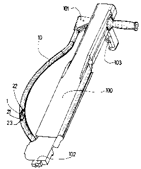
Figure 1 shows a sealing apparatus with a tube of
the present invention;
- Figure 2 shows a sectional view of a tube of the
prior art, with a nail;
- Figure 3 shows a sectional view of a first
embodiment of the tube of the present invention;
- Figure 4 shows a sectional view of a second
embodiment of the tube of the present invention;
- Figure 5 shows a sectional view of a third
embodiment of the tube of the present invention; and
- Figure 6 shows a sectional view of a fourth
embodiment of the tube of the present invention.

CA 02447011 2003-10-27
With reference to Figures 1 and 2, the sealing
apparatus 100, which is the example of a fastening
apparatus considered in this case, is used in a
substantially vertical position by the user who is able
to place a magazine pack containing nails 1 in a hopper
101 provided for this purpose. After unlocking of the
hopper 101, the nails 1 slide in a flexible tube 10 as
far as the front of a feeder, for indirect firing, in a
buffer guide 102. The user then simply has to actuate a
trigger 103 in order to entrain the nails into the
support via the feeder.
With reference to Figure 2, when a nail 1 with a
circular head 2 and a stem 4 slides in the tube 10,
namely, in this case, a tube 10 with a circular
effective inner cross section 11, the entire inner
surface 11 of the tube 10 is likely to be in contact
( 12 ) with the lateral surface 3 of the circular head 2
of the nail 1. Therefore, even if the diameter of the
circular head 2 of the nail 1 is smaller than that of
the circular inner cross section of the tube 10, there
may be surface contact 12 between the lateral surface 3
of the circular head 2 of the nail 1 and the inner
surface 11 of the tube 10, it being' possible for this
contact surface 12 statistically to occupy any portion
of the inner surface 11 when the nail 1 slides. Thus,
the entire inner surface 11 of the tube 10 is likely,
as nails 1 pass through, to enter into contact with the
circular head 2 of a nail 1. The entire inner wall 1I
of the tube 10 will thus be damaged by this passing-
through and become opaque.
The present invention aims to require the nail 1 to
make contact with certain inner portions of the tube,
enabling the rest of the inner surface to remain
transparent.
Thus, with reference to Figure 3, the effective inner

CA 02447011 2003-10-27
- 4 -
wall 21 of a tube 20 is ribbed longitudinally, the ribs
23 being shaped so that the contact 22 between the
lateral wall 3 of the circular head 2 of the nail 1 and
the effective inner wall 21 of the tube 20 occurs only
at the longitudinal ribs 23. The inner surface 21 will
therefore become opaque only at the ribs 23. The ribs
23 are in this case directly injection-moulded together
with the rest of the inner wall 21'of the tube 20 and
are made from the same material as that of the tube 20.
Reference has been made to the component elements of
Figure 3 in section in Figure 1 in order' to facilitate
understanding of the invention.
With reference to Figure 4, provision may be made for
an original tube 30 with a circular inner cross section
to which headings 33, made from. a material other than
that of the tube 30, are attached, forming longitudinal
ribs 33. Thus, the effective inner surface 31. of the
tube 30 is the result of the combination of the initial
circular inner surface and of the inner surface of the
headings. It is in fact the initial inner surface,
except at the locations of the headings 33, where the
inner surface taken into account is that of the
headings 33, until said surface is further away from
the centre of the tube than the initial inner surface.
This results in the lateral wall 3 of the circular head
2 of the nail 1 being able to enter into contact (32)
with the effective inner surface 3I of the tube 30 only
at the headings 33. The inner surface 31 will therefore
become opaque only at the headings 33.
With reference to Figure 5, it is possible to use a
tube 40 with an effective inner cross section 41 of
substantially polygonal shape, in this case a
substantially triangular shape. The dimensions of the
tube 40 are configured so that the :Lateral wall 3 of
the circular head 2 of the nail 1 can never enter into

CA 02447011 2003-10-27
- 5 -
contact (42) with the dihedra 43 of the inner surface
' 41 of the tube 40. The inner surface 41 will therefore
not become opaque at the dihedra 43. The choice of
dimensions of the tube 40 obviously affects the
proportion of inner surface 41 that. never enters into
contact with the nails 1.
With reference to Figure 6, it is also advantageous to
use a tube 50 with an effective inner cross section 51
of substantially rounded-star shape. The tube 50 is in
this case configured so that the lateral wall 3 of the
circular head 2 of the nail 1 can never enter into
contact (52) with the rounded dihedra 53 of the star
shape. The inner surface 51 will therefore not become
opaque at the dihedra 53.
By virtue of the various embodiments of the invention
described above, it is always possible to preserve, on
the wall of the tube, transparent portions right along
the tube. It goes without saying that any other shape
of effective inner cross section can be envisaged for
the tube, as long as it allows certain portions to
escape any contact with the lateral wall 3 of the head
2 of the nails 1.
It will be noted that the inner cross section of the
tube of the invention may be effective either for the
nails or for the operator. In fact, both notions have
been taken into account in order, by "effective°', to
imply "actual".

Representative Drawing
A single figure which represents the drawing illustrating the invention.
Administrative Status

2024-08-01:As part of the Next Generation Patents (NGP) transition, the Canadian Patents Database (CPD) now contains a more detailed Event History, which replicates the Event Log of our new back-office solution.

Please note that "Inactive:" events refers to events no longer in use in our new back-office solution.

For a clearer understanding of the status of the application/patent presented on this page, the site Disclaimer , as well as the definitions for Patent , Event History , Maintenance Fee  and Payment History  should be consulted.

Event History

Description Date
Time Limit for Reversal Expired 2011-10-27
Letter Sent 2010-10-27
Grant by Issuance 2007-05-01
Inactive: Cover page published 2007-04-30
Inactive: Final fee received 2007-02-19
Pre-grant 2007-02-19
Notice of Allowance is Issued 2006-08-21
Letter Sent 2006-08-21
Notice of Allowance is Issued 2006-08-21
Inactive: Approved for allowance (AFA) 2006-08-01
Inactive: IPC from MCD 2006-03-12
Amendment Received - Voluntary Amendment 2006-03-10
Inactive: S.30(2) Rules - Examiner requisition 2005-09-13
Amendment Received - Voluntary Amendment 2005-02-04
Application Published (Open to Public Inspection) 2004-04-30
Inactive: Cover page published 2004-04-29
Letter Sent 2004-02-13
Inactive: Single transfer 2004-01-20
Inactive: First IPC assigned 2003-12-23
Inactive: IPC removed 2003-12-23
Inactive: IPC assigned 2003-12-23
Inactive: IPC removed 2003-12-23
Inactive: IPC assigned 2003-12-23
Inactive: Courtesy letter - Evidence 2003-12-09
Filing Requirements Determined Compliant 2003-12-01
Inactive: Filing certificate - RFE (English) 2003-12-01
Letter Sent 2003-11-28
Application Received - Regular National 2003-11-28
Request for Examination Requirements Determined Compliant 2003-10-27
All Requirements for Examination Determined Compliant 2003-10-27

Abandonment History

There is no abandonment history.

Maintenance Fee

The last payment was received on 2006-10-03

Note : If the full payment has not been received on or before the date indicated, a further fee may be required which may be one of the following

  • the reinstatement fee;
  • the late payment fee; or
  • additional fee to reverse deemed expiry.

Patent fees are adjusted on the 1st of January every year. The amounts above are the current amounts if received by December 31 of the current year.
Please refer to the CIPO Patent Fees web page to see all current fee amounts.

Fee History

Fee Type Anniversary Year Due Date Paid Date
Request for examination - standard 2003-10-27
Application fee - standard 2003-10-27
Registration of a document 2004-01-20
MF (application, 2nd anniv.) - standard 02 2005-10-27 2005-10-03
MF (application, 3rd anniv.) - standard 03 2006-10-27 2006-10-03
Final fee - standard 2007-02-19
MF (patent, 4th anniv.) - standard 2007-10-29 2007-10-01
MF (patent, 5th anniv.) - standard 2008-10-27 2008-09-30
MF (patent, 6th anniv.) - standard 2009-10-27 2009-10-01
Owners on Record

Note: Records showing the ownership history in alphabetical order.

Current Owners on Record
SOCIETE DE PROSPECTION ET D'INVENTIONS TECHNIQUES SPIT
Past Owners on Record
ALAIN VETORETTI
PATRICK HERELIER
Past Owners that do not appear in the "Owners on Record" listing will appear in other documentation within the application.
Documents

To view selected files, please enter reCAPTCHA code :


To view images, click a link in the Document Description column. To download the documents, select one or more checkboxes in the first column and then click the "Download Selected in PDF format (Zip Archive)" or the "Download Selected as Single PDF" button.

List of published and non-published patent-specific documents on the CPD .

If you have any difficulty accessing content, you can call the Client Service Centre at 1-866-997-1936 or send them an e-mail at CIPO Client Service Centre.


Document
Description 
Date
(yyyy-mm-dd) 
Number of pages   Size of Image (KB) 
Description 2003-10-26 5 241
Abstract 2003-10-26 1 27
Drawings 2003-10-26 3 83
Claims 2003-10-26 1 29
Representative drawing 2003-12-22 1 10
Abstract 2005-02-03 1 24
Claims 2005-02-03 3 115
Drawings 2005-02-03 3 78
Claims 2006-03-09 3 113
Representative drawing 2007-04-12 1 11
Acknowledgement of Request for Examination 2003-11-27 1 188
Filing Certificate (English) 2003-11-30 1 170
Courtesy - Certificate of registration (related document(s)) 2004-02-12 1 107
Reminder of maintenance fee due 2005-06-27 1 109
Commissioner's Notice - Application Found Allowable 2006-08-20 1 162
Maintenance Fee Notice 2010-12-07 1 170
Correspondence 2003-11-30 1 27
Correspondence 2007-02-18 1 32