Note: Descriptions are shown in the official language in which they were submitted.
CA 02447411 2003-11-10
- 1 -
DESCRIPTION
RAW MATERIAL FOR PHOSPHATE FERTILIZER AND METHOD FOR
MANUFACTURING SAME
TECHNICAL FIELD
The present invention relates to a raw material for
phosphate fertilizer, which raw material consists essentially
of slag containing phosphate generated from dephosphorization
reaction in molten iron, and a method for manufacturing thereof .
BACKGROUND ART
Currently many of phosphate fertilizers are manufactured
from phosphate rock as the raw material. In the future, however,
the supply of phosphorus rock as the raw material may become short.
On the other hand, there is a request for effective use of slag
which is collected in the iron and steel making processes.
Responding to the movement, studies of utilizing the slag which
contains phosphate as a raw material for phosphate fertilizer
have recently become extensive. Since the phosphate existing
in slag is not water-soluble, the slag is expected as a slow-acting
fertilizer suitable for the promotion of environment-conserving
agriculture.
Thomas phosphate fertilizer is a most widely known
phosphate fertilizer manufactured from slag as the raw material.
Thomas fertilizer uses slag as the raw material, which slag is
generated in the process of smelting Thomas molten iron produced
CA 02447411 2003-11-10
- 2 -
from high phosphorus rock as the raw material, (normally [P] -
approximately 1. 8 to 2. 0 mass%) , and the slag has a characteristic
of high concentration of phosphate, ranging from 16 to 22 mass%.
The technology using the Thomas molten iron, however, has
limitations and problems of using high phosphorus rock as the
raw material, having high P concentration of molten iron after
dephosphorization, generating large quantity of slag, thus the
technology is currently adopted very little.
For the case of dephosphorization treatment of molten iron
prepared from common iron ore as the raw material, (molten iron
pretreatment), the P concentration in the molten iron before
dephosphorization is approximately from 0.1 to 0.2 mass%.
Accordingly, the phosphate concentration in the dephosphorized
slag which is generated and collected in conventional general
dephosphorization treatment process is only a level of 5 mass % ,
thus that type of slag does not have high concentration of
phosphate applicable to the raw material for phosphate
fertilizer.
In prior art, following-described technologies, for
example, are provided to obtain slag having high concentration
of phosphate applicable to a raw material for phosphate
fertilizer.
A method of executing the dephosphorization of molten
iron in two stage, (JP-A-8-3612, (the term "JP-A" referred to
herein signifies "Japanese Patent Laid-Open Publication")), in
which the slag containing phosphate generated in the first stage
of dephosphorization of molten iron is charged to a blast furnace
CA 02447411 2003-11-10
- 3 -
as a part of the blast furnace charge raw materials to increase
the P concentration in the molten iron tapped from the blast
furnace, and the slag having high concentration of phosphate is
collected in the second stage of molten iron dephosphorization.
A method of collecting slag having high concentration of
phosphate, (JP-A-8-3613), in which the slag that contains
phosphate generated during the converter smelting applied after
the molten iron dephosphorization is charged to a blast furnace
as a part of the blast furnace charge materials to increase the
P concentration of molten iron tapped from the blast furnace,
and then the slag having high concentration of phosphate is
collected by the molten iron dephosphorization.
A method of collecting slag having high concentration
of phosphate, (JP-A-11-158526), in which a slag that contains
phosphate obtained from dephosphorization treatment of molten
iron containing 0 . 15 mass o or less of P concentration is charged
to a molten iron bath, where the P in the slag is reduced and
extracted into the molten iron bath, to produce a molten iron
containing 0.5 to 3 massy P, followed by applying
dephosphorization treatment to the molten iron after removing
slag, thus the slag having high concentration of phosphate is
collected.
30 A method of separating and collecting a phase having
high concentration of phosphate from a slag generated in molten
iron dephosphorization, (JP-A-58-61210).
Those above-described conventional technologies are,
however, necessary to add special step to obtain slag having high
CA 02447411 2003-11-10
- 4 -
concentration of phosphate, which raises a problem of increased
cost for dephosphorization treatment and for slag collection.
Furthermore, the technologies ~, ~2 require the increase in the
P concentration in the molten iron, which may raise a problem
of difficulty in decreasing the P concentration of molten iron
after the dephosphorization treatment to a specific level. It
was also found that, even when these conventional technologies
achieve the increase in the phosphate concentration in the slag,
the phosphate in the slag is insoluble, in many cases, thus failing
to attain satisfactory fertilizer characteristics expected for
the level of obtained phosphate concentration.
DISCLOSURE OF THE INVENTION
An object of the present invention is to provide a raw
material for phosphate fertilizer having excellent fertilizer
characteristics, which raw material for fertilizer contains
phosphate generated by dephosphorization reaction in molten
iron.
Another object of the present invention is to provide a
method for manufacturing a raw material for phosphate fertilizer,
which method is suitable for obtaining the above-described raw
material for phosphate fertilizer.
A further object of the present invention is to provide
a phosphate fertilizer using the above-described raw material
for phosphate fertilizer, particularly to provide a phosphate
fertilizer which does not raise problems such as emissions during
fertilizer application, runoff carried by rainwater, and
CA 02447411 2003-11-10
- 5 -
hindrance of water and air permeation of ground, and which gives
favorable handling.
Many of the conventional technologies for utilizing slag
as a raw material for phosphate fertilizer focused on the
viewpoint of how to increase the concentration of phosphate in
slag to a level suitable for the phosphate fertilizer by adding
a special step to the manufacturing process.
Contrary to these conventional technologies, the inventors
of the present invention studied the compositions and
manufacturing methods of slag in terms of: ~ increasing the
concentration of phosphate in slag to a level of easy application
as a fertilizer in relation to the amount of fertilizer applied
and the like; 2~ securing the excellent fertilizer
characteristics by increasing the concentration of citric-
soluble phosphate among the phosphates in the slag, (citric-
soluble phosphate designates the phosphate which is able to be
absorbed when a plant generates an acid from the roots thereof) .
Through the study, the inventors of the present invention have
derived the following-described findings.
(1) From the viewpoint of obtaining slag having high
concentration of phosphate, suitable for a raw material for
phosphate fertilizer, a Ca0 source and an oxygen source are added
to a molten iron which sufficiently decreased the Si content
thereof to induce the dephosphorization reaction in the molten
iron, or the Ca0 source and the oxygen source are charged in
respective specific configurations or under respective specific
conditions to the molten iron to induce the dephosphorization
CA 02447411 2003-11-10
- 6 -
reaction in the molten iron, or both of the above-given treatment
are combined, thus the treatment can be conducted at very high
dephosphorization efficiency (reaction efficiency of
dephosphorization), and the quantity of generated slag is
extremely small, compared with conventional technologies. As
a result, when a molten iron having the P concentration of an
approximate range from 0.1 to 0.2 mass%, which is obtained in
normal blast furnace, is used, a single step of P-extraction
provides a slag having high concentration of phosphate, suitable
for a raw material for phosphate fertilizer, is obtained without
adding special step such as the step of concentrating P in molten
iron.
(2) The dephosphorization treatment which is given in the
step of preliminary treatment of molten iron uses a smelting agent
consisting mainly of CaO. To obtain high dephosphorization
reaction efficiency in the dephosphorization treatment,however,
it is understood that prompt slag formation (fusion) of the added
smelting agent (CaO) is important. On the other hand, it is
understood that the dephosphorization reaction proceeds more
favorably at low temperatures from the equilibrium point of view.
Accordingly, the treatment of molten iron is given at relatively
low temperatures. That low temperatures, however, are difficult
in slag formation of CaO. Consequently, conventional
technologies adopt CaF2 (fluorite) as the enhancer of slag
formation of CaO, and generally the dephosphorization treatment
of molten iron is carried out by charging CaF2 by approximate
amounts from 20 to 30 mass% to the quantity of CaO. As a result,
CA 02447411 2003-11-10
7 _
the slag collected in the dephosphorization treatment step
contains fluorine at an amount corresponding to the charged
amount of CaF2. That type of treatment, however, raises a problem
that, when the slag is used as the raw material for fertilizer,
sufficient citric-soluble phosphate concentration cannot be
attained because the fluorine in the slag fixes the phosphate
in the slag, thus the generated fluorine compound (fluoridated
apatite) contains small percentage of citric-soluble phosphate.
To solve that kind of problem, when the slag obtained in
above-given (1) having increased concentration of phosphate is
adjusted to a slag composition that is regulated to a specific
condition of the phosphate concentration and the fluorine
concentration, the citric-soluble phosphate concentration
requested as a fertilizer is fully attained. In particular,
since the slag described in above-given (1) is stably obtained
even under a treatment condition of minimized charged quantity
of CaF2, (or without charge of CaF2), the fluorine content can
be minimized to readily assure the necessary citric-soluble
phosphate concentration.
Based on the above-described findings, the raw material
for phosphate fertilizer provided by the present invention is
the following.
(I) A raw material for phosphate fertilizer consists
essentially of a slag which contains phosphate formed in a
dephosphorization reaction in molten iron, and the phosphate
content satisfies the formula (1)
[PzOs] ~ 5.6 x [F] + 7 (1)
CA 02447411 2003-11-10
_
where, [PZOS] is the phosphate content in slag, (mass%) , and [F]
is the fluorine content in slag, (mass%).
(II) A raw material for phosphate fertilizer consists
essentially of a slag which contains phosphate formed in a
dephosphorization reaction in molten iron, and the phosphate
content satisfies the formula (2)
(P205] ~ 5.6 x [F] + 10 (1)
where, [P205] is the phosphate content in slag, (mass°s) , and [F]
is the fluorine content in slag, (mass%).
According to the aspect (I) of the present invention, a
raw materialfor phosphate fertilizer givingfavorable phosphate
solubilization property is provided by the presence of 7 mass%
or more of citric-soluble phosphate in the slag.
According to the aspect (II) of the present invention, a
raw material for phosphate fertilizer giving particularly
favorable solubilization property of phosphate is provided by
the presence of 10 mass% or more of citric-soluble phosphate in
the slag.
Regarding the above-described slag as the raw material for
phosphate fertilizer, it is preferable that the fluorine content
is as small as possible to increase the content of citric-soluble
phosphate. In particular, it is most preferable that the
fluorine does substantially not exist, or that no fluorine exists
other than the fluorine which unavoidably enters during the
slag-generation step.
The above-described raw material for phosphate fertilizer
becomes the phosphate fertilizer without applying further
CA 02447411 2003-11-10
- 9 -
treatment, or becomes the main raw material for the phosphate
fertilizer. Therefore, the present invention provides that type
of phosphate fertilizer.
To manufacture a phosphate fertilizer from the above-
described raw material for phosphate fertilizer, the raw material
for phosphate fertilizer is preferably subjected to treatment
of pulverizing and/or seizing.
The above-described raw material for phosphate fertilizer,
specifically the raw material for phosphate fertilizer after
receiving the treatment of pulverizing and/or sizing, is
preferably subjected to a granulation step using an adequate
binder before becoming to the phosphate fertilizer. That kind
of phosphate fertilizer very little raises the problems such as
emissions during fertilizer application, runoff carried by
rainwater, and hindrance of ground water penetration and air
permeation, and which gives favorable handling property. In
addition, that kind of phosphate fertilizer is configured by
grains in regular and near-spherical shape so that it gives
easiness in handling.
As for the binder applied to the above-described
granulation step, starch, magnesium sulfate, and lignin are
particularly preferred from the point of granulation property
and of collapsibility after application of fertilizer particles ,
and it is preferable that at least one of them is used as the
main component thereof. As of these binders, starch is most
suitable because starch allows forming hardest granulates.
To obtain the slag (raw material for phosphate fertilizer)
CA 02447411 2003-11-10
- 10 -
that satisfies the above-given compositions and conditions, it
is necessary to manufacture the slag by a method to attain high
concentration of phosphate with least amount of charged CaF2, or
substantially without charge of CaF2. Furthermore, from the
point of slag manufacturing cost and of total treatment cost,
the manufacturing method is necessary be executable in a simple
facility and at low cost as far as possible without adding special
step of increasing the concentration of phosphate in slag, (for
example, a step of concentrating P in molten iron) . Particularly
suitable methods for manufacturing that kind of slag include:
a method of inducing dephosphorization reaction in molten iron
by charging an oxygen source and a Ca0 source to the molten iron
having sufficiently decreased Si concentration; and 2~ a method
of inducing the dephosphorization reaction in molten iron by
charging a Ca0 source and oxygen gas in respective specific
configurations and under respective specific conditions to the
molten iron. According to these manufacturing methods, a slag
having high concentration of phosphate, (a raw material for
phosphate fertilizer), is manufactured efficiently and at low
cost with very small quantity of charged CaF2 or substantially
without charge of CaF2.
That is, according to the above-described manufacturing
method ~, since the treatment is given to a molten iron in which
the Si concentration is fully decreased, high dephosphorization
efficiency is attained even under the condition of minimized
quantity of charged CaF2, or without charge of CaF2, the generated
Si02 amount is small, and the required amount of charged Ca0 source
CA 02447411 2003-11-10
- 11 -
is small, thus the generated slag quantity is small. As a result,
a slag having high concentration of phosphate and containing very
small amount of fluorine is efficiently manufactured at low cost
without adding special step.
According to the above-described manufacturing method ~2 ,
since the treatment is given by charging the Ca0 source and the
oxygen source in respective specific configurations and under
respective specific conditions, high dephosphorization
efficiency is attained even under a condition of very small
quantity of charged CaF2 or without charge of CaF2, thus the
quantity of generated slag is small. As a result, a slag having
high concentration of phosphate and containing very small amount
of fluorine is efficiently manufactured at low cost without
adding special step.
As for the method for manufacturing that type of raw
material for phosphate fertilizer, the present invention
provides the manufacturing method given below.
( 1 ) A method for manufacturing raw material far phosphate
fertilizer has the steps of: charging a Ca0 source and an oxygen
source to a molten iron containing 0 . 07 mass a or less Si to induce
dephosphorization reaction in the molten iron; and collecting
a slag containing phosphate, generated by the dephosphorization
reaction, as the raw material for phosphate fertilizer.
(2) A method for manufacturing raw material for phosphate
fertilizer has the steps of charging a Ca0 source and an oxygen
source into a vessel holding a molten iron therein to induce
dephosphorization reaction in the molten iron, and collecting
CA 02447411 2003-11-10
- 12 -
a slag containing phosphate, generated by the dephosphorization
reaction, as the raw material for phosphate fertilizer: wherein
at least a part of the gas oxygen and of the Ca0 source is blown
against the surface of molten iron bath via a top-blowing lance
to induce dephosphorization reaction in the molten iron; and the
charge rate B (kg/min/ton-molten iron) of the Ca0 source blown
against the surface of molten iron bath, converted to CaO,
satisfies the formula (3), preferably the formula (4), in
relation to the charge rate A (Nrn3/min/ton-molten iron) of the
oxygen source being charged into the vessel, converted to gas
oxygen:
0.3 ~ A/B ~~ 7 (3)
1.2 ~ A/B c 2.5 (4)
(3) A method for manufacturing raw material for phosphate
fertilizer has the steps of charging a Ca0 source and an oxygen
source into a pot type vessel or a torpedo car type vessel, holding
a molten iron therein, to induce dephosphorization reaction in
the molten iron, and collecting a slag containing phosphate
generated in the dephosphorization reaction as the raw material
for phosphate fertilizer; wherein at least a part of the gas oxygen
and of the Ca0 source is blown against the surface of molten iron
bath via a top-blowing lance, and a gas containing a powder is
blown into the molten iron via an immersion lance and/or a blowing
nozzle.
According to the above-given manufacturing method (1),
since the treatment is given to the molten iron containing 0.07
mass% or less Si, (preferably 0.05 mass% or less, and more
CA 02447411 2003-11-10
- 13 -
preferably 0. 03 mass% or less) , by charging a Ca0 source and an
oxygen source to induce dephosphorization reaction, the basicity
of slag increases to attain high phosphorus-distribution Lp,
which gives high dephosphorization efficiency and very small
amount of generated slag even with very small quantity of charged
CaF2 or with substantially no charge of CaF2. As a result, a single
treatment stage can manufacture a raw material (slag) for
phosphate fertilizer containing very little amount of fluorine
and having high concentration of phosphate without adding special
step.
The above-described manufacturing method (2) provides the
effect given below. That is, blow of gas oxygen against the
surface of molten iron bath induces generation of large amount
of Fe0 on the surface of molten iron bath (particularly in the
surface area of molten iron bath where the gas oxygen is blown) ,
which creates highly advantageous condition to enhance the slag
formation of CaO. By blowing the Ca0 source against the surface
of molten iron bath where that large amount of Fe0 is generated
and where large amount of-phosphorous oxide exists, and by
charging oxygen thereto, the charge rate of Ca0 source satisfies
the generation rate of Fe0 in the slag so that the Ca0 efficiently
exists in the vicinity of Fe0 and phosphorus oxide, which gives
high dephosphorization reaction efficiency. As a result, high
dephosphorization efficiency is attained with very small amount
of charged CAFZ or with substantially no charge of CaFz, and the
generated amount of slag decreases. Thus, a single treatment
stage can manufacture a raw material (slag) for phosphate
CA 02447411 2003-11-10
- 14 -
fertilizer containing very small amount of fluorine and having
high concentration of phosphate without adding special step.
According to the manufacturing method (2), the treatment
is applied to particularly a molten iron of low Si content, giving
high dephosphorization reaction efficiency even in a high
treatment temperature domain where conventional technologies are
accepted as difficult to perform, owing to the treatment
condition of small amount of charged CaF2 or without charge of
CaF2.
According to the above-described manufacturing method (3),
the following-given effect is attained. That is, blow of gas
oxygen against the surface of molten iron bath induces generation
of large amount of Fe0 on the surface of molten iron bath
(particularly in the surface area of molten iron bath where the
gas oxygen is blown), which creates a highly advantageous
condition to enhance the slag formation of CaO. By blowing the
Ca0 source against the surface of molten iron bath where that
large amount of Fe0 is generated, the slag formation of Ca0 is
effectively enhanced. Adding to the supply of the gas oxygen
and the Ca0 source against the surface of molten iron bath, when
a gas containing a powder is blown into the molten iron via an
immersion nozzle or a blowing nozzle, the molten iron is agitated
to efficiently supply the molten iron to the reaction interface,
which effectively enhances the dephosphorization reaction to
attain very high dephosphorization efficiency. As a result, in
the dephosphorization reaction treatment of molten iron using
a pot type vessel or a torpedo type vessel, high dephosphorization
CA 02447411 2003-11-10
- 15 -
efficiency is attained with very little amount of charged CaF2
or substantially without charge of CaF2, and the amount of
generated slag becomes small. Consequently, a single treatment
stage can manufacture a raw material (slag) for phosphate
fertilizer containing very small amount of fluorine and having
high concentration of phosphate without adding special step.
In addition, the raw material for fertilizer is
manufactured using the raw material for phosphate fertilizer,
obtained by each of the above-given manufacturing methods.
Therefore, the present invention provides that kind of method
for manufacturing phosphate fertilizer. On manufacturing the
phosphate fertilizer, it is preferred to execute the step of
pulverizing and/or seizing the above-described raw material far
phosphate fertilizer, and to execute the step of granulating
thereof while adding a binder to the raw material for phosphate
fertilizer.
BRIEF DESCRIPTION OF THE DRAWINGS
Fig. 1 is a graph showing the citric-so.lubilization
percentage of phosphate in a slag having respective compositions
given in Table 1 in relation to the fluorine content in the slag;
Fig. 2 is a graph showing the slag composition conditions
for raw materials for phosphate fertilizer according to the
present invention;
Fig. 3 illustrates an example of granulation step for the
raw material for phosphate fertilizer according to the present
invention;
CA 02447411 2003-11-10
- 16 -
Fig. 4 illustrates another example granulation step for
the raw material for phosphate fertilizer according to the
present invention;
Fig. 5 is a graph showing the relation between the Si content
in molten iron before the dephosphorization reaction treatment
and the dephosphorization efficiency;
Fig. 6 is a graph showing the relation between the molten
iron temperature at the beginning of dephosphorization reaction
treatment and the dephosphorization efficiency;
Fig. 7 is a graph showing the relation between the molten
iron temperature at the end of dephosphorization reaction
treatment and the dephosphorization efficiency;
Fig. 8 is a graph showing the relation between the molten
iron temperature at the beginning of dephosphorization reaction
treatment and the dephosphorization efficiency for the case that
a Ca0 source and an oxygen source are charged against the surface
of molten iron bath or into the molten iron bath at separate
positions or at the same position with each other;
Fig. 9 is a graph showing the relation between the molten
iron temperature at the beginning of dephosphorization reaction
treatment and the dephosphorization efficiency for the case that
quicklime is used as the Ca0 source and that the Ca0 source and
the oxygen source are charged against the surface of molten iron
bath or into the molten iron bath at separate positions or at
the same position with each other, and for the case that an
Fe0-Ca0-base solvent is used as the [Ca0 source + oxygen source] ;
Fig. 10 illustrates an example of the modes for carrying
CA 02447411 2003-11-10
- 17 -
out the method according to the present invention using a
converter type vessel;
Fig. 11 is a graph showing the relation between the Si
concentration in molten iron, the molten iron temperature at the
end of dephosphorization reaction treatment, and the lime
dephosphorization efficiency in the dephosphorization reaction
treatment without charging CaF2;
Fig. 12 is a graph showing the relation between the quantity
of charged CaFz and the lime dephosphorization efficiency in the
dephosphorization reaction treatment at temperatures of molten
iron at the end of dephosphorization treatment of from 1360°C to
1450°C;
Fig. 13 is a graph showing the influence of the ratio of
the Ca0 source charge rate X to the oxygen gas charge rate Y,
X/Y, on the dephosphorization percentage in the
dephosphorization reaction treatment using a pot type vessel;
Fig. 14 is a graph showing the relation between the
percentage of the charged quantity of Ca0 via a top-blowing lance
to the total added quantity of Ca0 source and the
dephosphorization percentage in the dephosphorization reaction
treatment using a pot type vessel for the case that total amount
of the Ca0 source is blown against the surface of molten metal
bath via a top-blowing lance and for the case that the total amount
of the Ca0 source is inj ected into the molten iron via an immersion
lance and/or a blowing nozzle;
Fig. 15 is a graph showing the relation between the Si
concentration in molten iron before the dephosphorization
CA 02447411 2003-11-10
- 18 -
reaction treatment and the necessary quantity of Ca0 source
(lime) in using a pot type vessel for the cases of the method
according to the present invention and of the conventional
method;
Fig. 16 illustrates an example of the mode carrying out
the present invention using a pot type vessel; and
Fig. 17 is a graph showing the relation between the ratio
of the oxygen charge rate A to the Ca0 source charge rate B, A/B,
and the phosphorous concentration in molten iron after the
dephosphorization reaction treatment, in Embodiment 2.
Detailed Description of the Invention
The raw material for phosphate fertilizer according to the
present invention consists essentially of a slag which contains
phosphate formed in a dephosphorization reaction in molten iron,
wherein the content of phosphate satisfies the formula (1) , and
preferably satisfies the formula (2):
[P205] ~ 5.6 x [F] + 7 (1)
[PZOS] ~ 5.6 x [F] + 10 (2)
where, [P205] is the content of phosphate in slag, (mass%) ,
and [F] is the content of fluorine in slag, (mass%).
A typical example of that type of slag is a molten iron
dephosphorized slag which is collected in the preliminary
treatment step for blast furnace molten iron. The slag is,
however, not limited to the one given above, and the slag as the
raw material for phosphate fertilizer according to the present
invention includes slag obtained by arbitrary manufacturing
CA 02447411 2003-11-10
- 19 -
method. The preliminary treatment step for the blast furnace
molten iron is the treatment aiming at dephosphorization,
desulfurization, and the like of the molten iron, given before
the decarbonization treatment step. As for the
dephosphorization treatment for the molten iron, which aims
mainly at dephosphorization, a smelting agent (lime or the like)
which is the Ca0 source and an oxygen source (gas oxygen and/or
solid oxygen source) are charged to the molten iron, thus the
dephosphorization reaction fixes P in the molten iron to the
generated slag to conduct the dephosphorization of the molten
iron.
As described before, when fluorine exists in the slag,
fluoridated apatite (9Ca0~3P205~CaF2) is generated to fix the
phosphate so that the solubilization property of phosphate
(citric-solubilization property) degrades totally in the slag.
On the other hand, if no fluorine exists, only the hydroxyl apatite
is formed even if the percentage of Ca0 is large, thus no
degradation in solubilization property of phosphate occurs.
Table 1 shows the compositions of slag obtained by
successively applying the desiliconization and desulfurization
to a molten iron tapped from a blast furnace, followed by inducing
dephosphorization reaction by charging a Ca0 source and an oxygen
source to the molten iron, (hereinafter referred to as the
"dephosphorization reaction treatment"). The
dephosphorization reaction treatment used a converter type
vessel, and applied the two methods of charge of oxygen source
and Ca0 source : namely, ( 1 ) a method of blowing gas oxygen against
CA 02447411 2003-11-10
- 20 -
the surface of molten iron bath via a top-blowing lance, while
top-feeding lumps of lime (Ca0 source) ; and (2) a method of blowing
lime powder (Ca0 source) against the surface of molten iron bath
using gas oxygen as the carrier via a top-blowing lance. The
respective charges were given with different charged quantities
of CaF2.
As shown in Table 1, the term "C-P205 (citric-soluble
phosphate) " designates the phosphate soluble in 2 o citric acid
solution (pH 2) , and the term "citric-solubilization percentage
of phosphate" designates the percentage (mass%) of citric-
soluble phosphate in total phosphate (P205) existing in the slag.
Both of these characteristics were~analyzed conforming to the
respective official fertilizer analytical methods.
CA 02447411 2003-11-10
- 21 -
Table 1
Slag Citric-
composition
(mass)
Slag solubilization
Si02 Ca0 A1Z03 Mg0 T-Fe F PZOS C-P205percentage
of
phosphate
(%)
A 12 48 7 5 6 1.21 10.5 5.0 48
B 12 39 6 8 9 0.86 10.4 5.2 50
C 12 39 6 8 9 0.84 10.2 5.2 51
D 13 44 5 5 8 0.56 11.5 8.1 70
E 12 46 6 4 8 0.42 10.8 8.2 76
F 14 45 4 2 8 0.26 13.9 10.5 76
G 12 39 6 8 9 0.35 8.5 6.8 80
H 13 45 5 3 9 0.13 13.5 11.7 87
I 13 42 6 3 8 0.15 11.9 11.3 95
J 13 42 6 3 8 0.15 8.6 8.2 95
K 12 39 6 8 9 0.08 7.4 7.2 97
L 13 41 5 4 9 0.07 10.6 10.2 97
M 14 44 5 5 8 0.00 10.3 10.2 99
Fig. 1 is a graph showing the citric-solubilization
percentage of phosphate in a slag having respective compositions
given in Table 1 in relation to the fluorine content in the slag.
According to the figure, the citric-solubilization percentage
of phosphate of the slag which substantially does not contain
fluorine is almost 100% (990), while the slag which contains
fluorine decreases the citric-solubilization percentage of
phosphate with the increase in the content of fluorine. The lower
limit of citric-solubilization percentage of phosphate is,
however, about 50o independent of the fluorine content.
The above-described result showed that all the fluorine
CA 02447411 2003-11-10
- 22 -
in slag becomes fluoridated apatite (9Ca0~3P205~CaFz) , that the
solubilization percentage of phosphate (citric-solubilization
percentage) in the apatite is about 50%, and that the
solubilization percentage of phosphate (citric-solubilization
percentage) in compounds other than fluoridated apatite is about
100 % .
Accordingly, the present invention selects the specified
value (lower limit) of the quantity of citric-soluble phosphate
necessary for the raw material for phosphate fertilizer to 7 mass % ,
preferably 10 mass%, considering the efficacy of the fertilizer
applied to farmland. If the quantity of citric-soluble phosphate
in fertilizer is 7 mass% or more, preferably 10 mass% or more,
the quantity of applied fertilizer does not become large, and
the usefulness as the fertilizer is satisfactorily secured.
As for the fluoridated apatite (9Ca0~3P205~CaF2) , 3 x 142
g of phosphate is fixed to 38 g of F. In that case, since about
50% of the phosphate contained is citric-soluble phosphate,
3 x 142 (g) /38 (g) /2=5. 6
is derived. That is, the citric-soluble phosphate in the
phosphate which becomes to fluoridated apatite is 5. 6 x [F] . To
contain 7 mass% or more of citric-soluble phosphate, the
phosphate which becomes to fluoridated apatite is necessary to
be added to the target quantity of citric-soluble phosphate.
Therefore, the quantity of phosphate [P205] (mass%) and the
quantity of fluorine [F] (mass%) in the slag are required to
satisfy the formula (1)
[P205] ~ 5.6 x [F] + 7 (1)
CA 02447411 2003-11-10
- 23 -
Similarly, to contain the citric-soluble phosphate to 10
mass% or more, the quantity of phosphate [P205] (mass%) and the
quantity of fluorine [F] (mass%) in the slag are required to
satisfy the formula (2)
[P205) ? 5.6 x [F] + 10 (2)
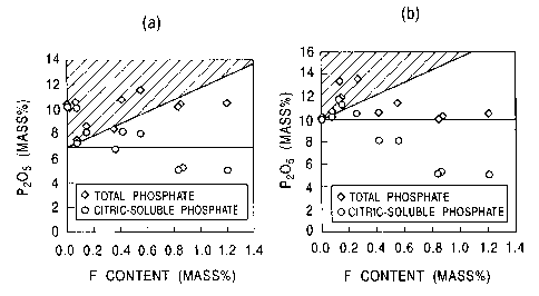
Fig. 2 (a) shows the range of phosphate content and of the
fluorine content specified by the formula (1) , (shown by shaded
portion). Fig. 2(b) shows the range of phosphate content and
of the fluorine content specified by the formula (2) , (shown by
shaded portion). Each of these figures shows the content of
phosphate and the content of citric-soluble phosphate in total
slag for individual compositions given in Table 1 at upper and
lower portions of the figure. As shown in the figures, the
desired quantity of citric-soluble phosphate is secured only when
the formula (1) and the formula (2) are satisfied.
Other than the above-described fluoridated apatite
(9Ca0~3PZb5~CaF2) , slag contains silicocarnotite (5Ca0~P205~Si02) ,
nagelshmidtite (7Ca0~PZOS~2Si02), and the like as the main
compounds. Nevertheless, the phosphate existing in these
compounds shows favorable solubilization property (about 100%
of citric-solubilization percentage).
To increase the content of citric-soluble phosphate as far
as possible, the above-described slag as the raw material for
phosphate fertilizer preferably contains as small amount of
fluorine as possible, and particularly it is most preferable to
contain no fluorine other than the fluorine unavoidably enters
during the slag-generation step. To do this, it is preferable
CA 02447411 2003-11-10
- 24 -
that the quantity of charged CaF2 is minimized on conducting the
dephosphorization reaction in molten iron, more preferably
substantially no CaF2 is charged (or no CaF2 is charged other than
the unavoidably entered CaF2).
The above-described raw material for phosphate fertilizer
is used as the phosphate fertilizer without subjecting to further
treatment, or becomes the main raw material for phosphate
fertilizer. For the latter case, other fertilizer-component is
added to an adequate amount.
The above-described raw material for phosphate fertilizer
is preferably converted to the phosphate fertilizer after treated
by pulverizing and/or sizing thereof.
There is no specific limitation on the method of pulverizing
the raw material for phosphate fertilizer, and arbitrary method
is applicable. For example, pulverization can be conducted using
pulverizer such as j aw crusher, rod mill , Fred mill , and impeller
breaker. The sizing may be carried out using arbitrary sieving
unit. The sizing may be given by arbitrary sizing unit. The
sizing treatment may be applied after pulverizing the raw
material for phosphate fertilizer.
The raw material for phosphate fertilizer after treated
by pulverizing and/or sizing treatment is preferably subjected
to the granulation step using an adequate binder before using
as the phosphate fertilizer. The phosphate fertilizer thus
granulated generates very little problem of emissions during
application, run-off by rainwater, and hindrance of water and
air permeation of ground. In addition, that kind of phosphate
CA 02447411 2003-11-10
- 25 -
fertilizer is configured by grains in regular and near-spherical
shape so that it gives easiness in handling.
The method for granulating slag has no specific limitation,
and general methods are applicable. For example, the pulverized
slag obtained by the above-described pulverizing treatment may
be mixed with a binder in a mixer, and the mixture may be granulated
in a granulator while adding an adequate volume of water, followed
by drying the mixture.
Applicable granulator may be the one generally used. For
example, rotary dish type granulator or rotary cylindrical
granulator is applicable. If the granulated slag is outside the
specified grain size range, the slag is preferably recycled to
the granulator directly or after applying pulverizing treatment
to reuse as a part of the raw material.
Fig. 3 shows an example of granulation step of the raw
material for phosphate fertilizer. The pulverized slag (raw
material for phosphate fertilizer) 10 obtained by the above-
described pulverizing treatment is charged to a hopper 11 using
shovel loader or the like. The weighed pulverized slag 10 is
charged to a drum type rotary granulator 13 from the hopper 11
via a conveyer 12. A specific quantity of binder 14 stored in
a vessel 15 is charged to the drum type rotary granulator 13.
By the rotary action of the drum type rotary granulator 13 , the
pulverized slag 10 and the binder 14 are mixed together to become
granules. After that, the granulated slug is dried in a drier
16 , which is then fed to a sieve 18 via an elevator 17 to undergo
sieving. The sieved slag is cooled in a cooler 19 to become the
CA 02447411 2003-11-10
- 26 -
granulated fertilizer. It is also possible to sieve the slag
after cooling thereof in the cooler 19 before granulating
thereof .
Fig. 4 shows another example of granulation step of the
raw material for phosphate fertilizer. The pulverized slag 10
obtained by the above-described pulverizing treatment is charged
to a hopper 21. The weighed pulverized slag 10 is charged to
a mixer 24 from the hopper 21. A specific quantity of binder
14 stored in a vessel 23 is also charged to the mixer 24, where
the pulverized slag 10 and the binder 14 are mixed together. The
mixture is fed to a dish type granulator 25 to granulate the
mixture therein. The slag granulated in the dish type granulator
25 is supplied to a belt conveyer 26 for undergoing drying in
the drier 16 similar to the step of Fig. 3. Then, the slag is
supplied to the sieve 18 by the elevator 17 to undergo sieving.
Further the slag is cooled in the cooler 19 to become the
granulated fertilizer.
The kind of binder applied to the granulation step has no
specific limitation. Applicable binder may be one or combination
of phosphate, clay, bentonite, polyvinylalcohol, carboxymethyl
cellulose,polyacrylic acid,molasses, lignin,magnesiumsulfate,
and starch. From the point of granulation property and of
collapsibility of fertilizer grains after applied, starch,
magnesium sulfate, and lignin are suitable, and one or more of
them is preferably used as the main components of the binder.
On manufacturing granulated fertilizer by granulating raw
material for phosphate fertilizer, the required characteristics
CA 02447411 2003-11-10
- 27 -
of binder include: 10 to provide excellent granulation property;
0 to provide ready collapse of fertilizer grains (granulated
fertilizer) after applied to disperse into soil; 3U to provide
sufficient hardness of grains not to collapse thereof during
manufacturing and in the course of transportation before the
application of the fertilizer; and ~ to give no bad influence
of the binder components on the environment including soil. All
the above-given starch, magnesium sulfate, and lignin satisfy
these requirements. As of these, starch is particularly
preferred because the starch provides particularly high hardness
of the granulated fertilizer grains, and the starch dissolves
in rain or water in soil to allow collapsing the granulated
fertilizer grains at an adequate speed. With the addition of
water, starch is impasted, and further the drying of the pasted
starch generates solidified starch. Therefore, starch provides
excellent granulation performance. Furthermore, starch is
decomposed by microorganisms in soil, thus the starch does not
give bad influence on plants and environment.
Applicable starch used as the binder includes the one
manufactured from corn, tapioca, wheat, potato, and rice. These
various starches differ in the percentages of components, or
amylose (long straight chain of d-glucose molecules) and
amylopectin (branched chain of d-glucose molecules), depending
on the kind of raw material. Glutinous rice and glutinous corn
contain large percentage of amylopectin. Furthermore,
applicable kinds of starches may be raw starch or processed starch
which is a starch processed by heat, acid, alkali, salt, or enzyme.
CA 02447411 2003-11-10
- 28 -
Starches having property of pasting by themselves are suitable
for the granulation binder independent of the kind thereof.
Preferable mean particle size of thus granulated phosphate
fertilizer is in a range from 0. 5 to 6 mm. The fertilizer having
mean particle sizes of lower than 0.5 mm gives poor handling
performance because those small particles are blown off by wind
during application. The fertilizer having mean particle sizes
exceeding 6 mm is difficult for uniform distribution on applying
thereof . More preferable particle size range is from 1 to 5 mm.
A method for manufacturing raw material for fertilizer
suitable for obtaining the raw material for phosphate fertilizer
according to the present invention is described in the following.
To obtain a slag that satisfies the above-described
compositions and conditions by the dephosphorization reaction
treatment of molten iron, it is necessary to generate slag having
high concentration of phosphate with very small quantity of
charged CaF2 or substantially without charge of CaFz.
Furthermore, from the point of slug-manufacturing cost and of
total treatment cost, the manufacturing method is necessary to
be executed with a simple process as far as possible and at low
cost without adding special step for concentrating the phosphate
in the slag, (for example, the step of concentrating P in molten
iron). Those kinds of requirements are satisfied by several
novel manufacturing methods described below.
The first manufacturing method which is provided by the
present invention is the one to conduct treatment on a molten
iron that has sufficiently low level of Si concentration.
CA 02447411 2003-11-10
- 29 -
According to the manufacturing method, high dephosphorization
efficiency is attained even under a condition of minimum amount
of charged CaF2 or without charge of CaF2, the quantity of
generated Si02 is small , and the necessary amount of charging Ca0
source is small, thus the amount of generated slag is small.
Consequently, the slag which has high concentration of phosphate
and contains very small amount of fluorine is manufactured
efficiently at low cost without adding special step.
The second and the third manufacturing methods which are
provided by the present invention are the ones to conduct
treatment by charging a Ca0 source and gas oxygen in respective
specific configurationsor under respective specific conditions.
According to the manufacturing methods, high dephosphorization
efficiency is attained even with a minimized quantity of charged
CaF2 or without charge of CaF2, and the necessary amount of charged
Ca0 source is small, thus the amount of generated slag is small.
As a result, a slag which has high concentration of phosphate
and contains very small amount of fluorine is efficiently
manufactured at low cost without adding special step.
The first method for manufacturing raw material for
phosphate fertilizer according to the present invention is
described in the following.
The inventors of the present invention studied the methods
which are able to manufacture a slag with high phosphate content
at a high dephosphorization reaction efficiency through the
treatment of dephosphorization reaction in molten iron, and found
that high dephosphorization efficiency is attained with very
CA 02447411 2003-11-10
- 30 -
small amount of charged CaF2 or substantially without charge of
CaF2 by conducting the dephosphorization reaction treatment of
charging a Ca0 source and an oxygen source to a molten iron
containing 0.07 mass% or less Si02, preferably 0. 05 mass% or less,
more preferably 0. 03 mass% or less, and that a raw material (slag)
for phosphate fertilizer which contains very small amount of
fluorine and has high concentration of phosphate is manufactured.
Consequently, according to the first manufacturing method
of the present invention, the slag as the raw material for
phosphate fertilizer is manufactured by applying
dephosphorization reaction treatment by charging a Ca0 source
and an oxygen source to a molten iron that contains 0.07 mass%
or less Si02, preferably 0. 05 mass o or less, and more preferably
0.03 mass% or less.
Furthermore, it was found that the raw material for
phosphate fertilizer which is better in terms of phosphate
concentration and the content of fluorine is stably manufactured
owing to the optimization of the molten iron temperature at the
beginning of the treatment and the molten iron temperature at
the end of the treatment in the above-described dephosphorization
reaction treatment of molten iron, and owing to further increase
in the dephosphorization efficiency by the charge of the Ca0
source and the oxygen source under respective specific
conditions.
Fig. 5 is a graph showing the relation between the Si content
in molten iron before the dephosphorization reaction treatment
and the dephosphorization efficiency (phosphorus-distribution
CA 02447411 2003-11-10
- 31 -
Lp) for the case that a molten iron which was subjected to
desiliconization treatment to adjust the Si content in the molten
iron using a converter type vessel, (under the,conditions of
1280~C or higher molten iron temperature at the beginning of the
treatment, 1280°C to 1360 of molten iron temperature at the end
of the treatment, and top-feed of quicklime) . When the Si content
in the molten iron being subjected to the dephosphorization
reaction treatment becomes to 0. 07 mass% or below, the increased
basicity of the slag increases rapidly the phosphorus-
distribution Lp,(Lp is an index of the dephosphorization
efficiency; Lp = (mass% P) / [mass% P] , where (mass o P) designates
the P concentration in the slag, and [mass% P] designates the
P concentration in the molten iron) , and a significant increase
in the dephosphorization efficiency appears. The
dephosphorization efficiency increases with the decrease in the
Si content in the molten iron, and the highest dephosphorization
efficiency is attained at Si contents of about 0 . 03 mass o or below
in the molten iron.
The dephosphorization reaction treatment at that high
dephosphorization efficiency increases the phosphate
concentration in the slag. The amount of generated slag becomes
extremely small because of the low Si content of the molten iron
before the dephosphorization reaction treatment and because of
the small amount of charged Ca0 to adjust the basicity. Since
the high dephosphorization efficiency is attained, the treatment
is conducted with very small amount of charged CaF2 or
substantially without charge of CaF2. Accordingly, a single
CA 02447411 2003-11-10
- 32 -
treatment stage can manufacture a raw material (slag) for
phosphate fertilizer containing very little amount of fluorine
and having high concentration of phosphate without adding special
step.
The concentration of phosphate in the slag generated in
the dephosphorization reaction treatment of molten iron,
described above, naturally differs with the P concentration in
the molten iron before and after the treatment, with the amount
of generated slag, or the like. Generally, however, the
phosphate concentration in the slag is 7 mass % or more, (normally
approximately 7 to 10 mass%) . According to a method described
later, in which the Ca0 source is ejected (sprayed) against the
bath surface of the reaction treatment vessel from above the bath
surface, and in which preferably the ratio of the charge rate
of Ca0 source to the charge rate of oxygen source is regulated
to a specific range, higher phosphate concentration, or generally
mass% or more (normally approximately 10 to 15 mass%), is
attained.
On conducting dephosphorization reaction treatment, if the
Si content of the molten iron exceeds the above-given upper limit
(0.07 mass%, preferably 0.05 mass%, and more preferably 0.03
mass%) , the dephosphorization reaction treatment is given after
applying desiliconization treatment to decrease the Si content
in the molten iron to not more than the upper limit. Generally,
molten iron tapped from a blast furnace or the like contains Si
to approximate level of from 0 . 30 to 0 . 50 mass % , and, for a molten
iron containing that normal level of Si, the desiliconization
CA 02447411 2003-11-10
- 33 -
treatment is essentially requested.
The desiliconization treatment may be given during the
molten iron desiliconization step, (for example,
desiliconization at casthouse), or during the desiliconization
in a vessel. For the case of desiliconization in vessel, the
vessel may be molten iron pot, ladle such as charge pot, torpedo,
or the like. By charging a desiliconization agent to the vessel
to agitate the contents,efficient desiliconizationis performed.
Applicable desiliconization agent includes solid oxygen source
(normally iron oxide such as mill scale) , gas oxygen source (gas
oxygen or oxygen-laid gas), or both of them.
The desiliconization treatment given in a ladle can fully
agitate the molten iron owing to the shape thereof to hold the
molten iron, thus giving better desiliconization efficiency than
that attained in other molten iron desiliconization steps (for
example, desiliconization step conducted in casthouse and in
torpedo) . Consequently, when the Si content in the tapped molten
iron is relatively high, it is preferable to apply
desiliconization treatment in the ladle or to apply
desiliconization in the ladle after conducted the casthouse
desiliconization. Conventionally-given casthouse
desiliconization or the like gives poor desiliconization
efficiency, and furthermore, that type of treatment uses only
a solid oxygen source (mill scale or the like) as the
desiliconization agent, thus there arises a problem of decreasing
in the molten iron temperature. To the contrary, the
desiliconization treatment given in a ladle is easy to maintain
CA 02447411 2003-11-10
- 34 -
and stabilize the molten iron temperature because gas oxygen can
be charged as the desiliconization agent, and is easy to adjust
the molten iron temperature because the charge of solid oxygen
source is also available.
The dephosphorization reaction treatment is conducted by
charging a Ca0 source and an oxygen source to a molten iron
containing Si at a level of 0. 07 mass o or less, preferably 0 . 05
mass% or less , and most preferably 0 . 03 mass% or less . Normally
the dephosphorization reaction treatment is conducted using a
molten iron pot or a converter type vessel. The applied vessel,
however, has no limitation, and in some cases, a single vessel
may be used for successive application of desiliconization
treatment and dephosphorization reaction treatment. In that
case, the dephosphorization reaction treatment is given after
removing at least a part of slag after the desiliconization
treatment.
Although quicklime is generally used as the Ca0 source,
the Ca0 source is not limited to quicklime. The Ca0 source and
the solid oxygen source are charged to the treatment vessel by
top-feed, injection, or other methods. As for the gas oxygen
source, generally oxygen gas is blown into and/or sprayed to the
molten iron using lance, bottom-blowing nozzle, or the like.
There is no specific limitation on the execution method
and treatment condition of the dephosphorization reaction
treatment. It is, however, preferable that the treatment is
conducted under the conditions given below. Through the
treatment conduced under the conditions , a slag containing small
CA 02447411 2003-11-10
- 35 -
amount of fluorine and having high concentration of phosphate
is more stably obtained.
(1) The molten iron temperature at the beginning of
dephosphorization reaction treatment is controlled to 12800C or
above, (preferably 1320°C or above) .
(2) The molten iron temperature at the end of
dephosphorization reaction treatment is controlled to a range
from 1280°C to 1360°C, (preferably from 1300°C to
1340°C) .
(3) The Ca0 source and the oxygen source are charged
against the surface of molten iron bath or into the molten iron
bath at the same position with each other.
(4) An Fe0-Ca0-base solvent is charged as a part or total
of the Ca0 source.
Regarding the condition of (1), the method of
dephosphorization reaction treatment of a molten iron of low Si
content increases the basicity of slag, (= Ca0/Si02) , to increase
the melting temperature, which results in insufficient initial
slag formation of CaO, thus likely inducing degradation in
dephosphorization efficiency. To prevent that type of decrease
in the dephosphorization efficiency, it is effective that the
molten iron temperature at the beginning of the dephosphorization
reaction treatment is set to a standard value or higher
temperature to enhance the initial slag formation in initial
period, thus generating the fused Fe0 in early stage . To do this ,
it is preferable that the molten iron temperature at the beginning
of the dephosphorization reaction treatment is controlled to
1280°C or above, more preferably 1320°C or above.
CA 02447411 2003-11-10
- 36 -
Fig. 6 is a graph showing the relation between the molten
iron temperature at the beginning of dephosphorization reaction
treatment and the dephosphorization efficiency for the cases that
the dephosphorization reaction treatment is conducted in a
converter type vessel and that the treatment is conducted in a
molten iron pot under the conditions of 1280°C to 1360°C of
molten
iron temperature at the end of dephosphorization reaction
treatment, 0.07 mass% or less Si content in the molten iron before
the dephosphorization reaction treatment, using the converter
type vessel with top-feed of quicklime, and the molten iron pot
with both the top-feed of quicklime and the injection of quicklime
in a part. The figure shows that particularly high
dephosphorization efficiency (phosphorus-distribution Lp) is
attained by controlling the molten iron temperature at the
beginning of the treatment to 1280°C or above, preferably 1320°C
or above. According to the figure, the agitation efficiency is
higher in the dephosphorization reaction treatment in the
converter type vessel than that in the dephosphorization reaction
treatment in the molten iron pot, so the former treatment gives
higher dephosphorization efficiency in a limited treatment
period. With that high dephosphorization efficiency and small
amount of generated slag, the minimization of the amount of
charged CaF2 or without charge of CaF2 is realized, and furthermore,
the phosphate concentration in slag is effectively increased,
thus the raw material (slag) for phosphate fertilizer having
excellent fertilizer performance is stably manufactured.
As for the above-described condition (2), the
CA 02447411 2003-11-10
- 37 -
dephosphorization efficiency of molten iron is favorable at
relatively low molten iron temperatures from the equilibrium
point of view. However,excessivelylow molten iron temperatures
result in insufficient slag formation of CaO, thus the
dephosphorization efficiency decreases. Since the treatment is
actually conducted within a limited period of operation, the
treatment temperature has an adequate range from the point of
dephosphorization efficiency. The adequate temperature range
is from 1280°C to 1360°C of the molten iron temperature at the-
end of the dephosphorization reaction treatment, more preferably
from 1300°C to 1340°C. By completing the dephosphorization
reaction treatment at that molten iron temperature range , better
dephosphorization efficiency is secured.
Fig. 7 is a graph showing the relation between the molten
iron temperature at the end of dephosphorization reaction
treatment and the dephosphorization efficiency for the case that
the dephosphorization reaction treatment (charge of the Ca0
source is given by top-feed of quicklime) is conducted by a
converter type vessel, (1280~C or more of the molten iron
temperature at the beginning of dephosphorization reaction
treatment, and 0.07 mass$ or less of the Si content in the molten
iron before ending the dephosphorization reaction treatment).
The figure shows that particularly high dephosphorization
efficiency (phosphorus-distribution Lp) is attained at molten
iron temperatures at the end of the dephosphorization reaction
treatment ranging from 1280°C to 1360°C, preferably from
1300°C
to 1340°C. With that high dephosphorization efficiency and small
CA 02447411 2003-11-10
- 38 -
amount of generated slag, the minimization of the amount of
charged CaF2 or without charge of CaF2 is realized, and furthermore,
the phosphate concentration in slag is effectively increased,
thus the raw material {slag) for phosphate fertilizer having
excellent fertilizer performance is stably manufactured.
For the above-given condition (3) , the slag formation by
the reaction of [Ca0 + Fe0] is enhanced by charging the Ca0 source
and the oxygen source to the same position on the surface of bath
or in the bath in the treatment vessel, or by simultaneously
charging the Ca0 source to the point of Fe0 generation resulted
from the oxygen source charging, thus the dephosphorization
efficiency increases.
Fig. 8 is a graph showing the relation between the molten
iron temperature at the beginning of dephosphorization reaction
treatment and the dephosphorization efficiency in the
dephosphorization reaction treatment using a converter type
vessel, (1280 to 1360°C of the molten iron temperature at the
end of dephosphorization reaction treatment, and 0.07 masso or
less of the Si content in the molten iron before the
dephosphorization reaction treatment), for two cases: charging
the Ca0 source and the oxygen source to separate positions on
the surface of bath or in the bath in the vessel, (top-feeding
for the quicklime and top-blowing for the gas oxygen); and
charging the Ca0 source and the oxygen source to the same position
on the surface of bath or in the bath in the vessel, (top-blowing
for [quicklime + oxygen gas]). According to Fig. 8, the case
of charging the Ca0 source and the oxygen source to the same
CA 02447411 2003-11-10
- 39 -
position on the surface of bath or in the bath in the vessel
provides superior dephosphorization efficiency (phosphorus-
distribution Lp) to the case of charging the Ca0 source and the
oxygen source to separate positions on the surface of bath or
in the bath in the vessel. With that high dephosphorization
efficiency and small amount of generated slag, the minimization
of the amount of charged CaF2 or without charge of CaF2 is realized,
and furthermore, the phosphate concentration in slag is
effectively increased, thus the rawrnaterial (slag) for phosphate
fertilizer having excellent fertilizer performance is stably
manufactured.
As for the above-described condition (4), use of an
Fe-O-Ca0-base solvent which contains Ca0 and a solid oxygen
source, as a part or the total of the Ca0 source, provides
equivalent function and effect with the case of above-described
(3) in which the Ca0 source and the oxygen source are charged
to the same position on the surface of bath or in the bath in
the vessel. Examples of applicable Fe0-Ca0-base solvent are
calcium ferrite and sinter of mixture of calcia and ferrite.
Fig. 9 is a graph showing the relation between the molten
iron temperature at the beginning of dephosphorization reaction
treatment and the dephosphorization efficiency in the
dephosphorization reaction treatment using a converter type
vessel, (1280°C to 1360°C of the molten iron temperature at the
end of dephosphorization reaction treatment, and 0.07 masso or
less of the Si content in the molten iron before the
dephosphorization reaction treatment), for two cases: for the
CA 02447411 2003-11-10
- 40 -
case that quick lime is used as the Ca0 source and that the Ca0
source and the oxygen source are charged against the surface of
bath or into the bath in the vessel at separate positions from
each other, (top-feed for the quicklime, and top-blowing for the
gas oxygen), and for the case that an Fe0-Ca0-base solvent, (a
mixed sinter of Fe0 + Ca0), is used as the Ca0 source, (top-
feed for the solvent, and top-blow for the oxygen gas) . According
to Fig. 9 , the case of charging the Fe0-Ca0-base solvent as the
Ca0 source provides superior dephosphorization efficiency
(phosphorus-distribution Lp) to the case of charging the Ca0
source and the oxygen source to separate positions on the surface
of bath or in the bath in the vessel. With that high
dephosphorization efficiency and small amount of generated slag,
the minimization of the amount of charged CaF2 or without charge
of CaF2 is realized, and furthermore, the phosphate concentration
in slag is effectively increased, thus the raw material (slag)
for phosphate fertilizer having excellent fertilizer performance
is stably manufactured.
As shown in Fig. 6; the dephosphorization reaction
treatment provides particularly strong effect
(dephosphorization efficiency) by using a converter type vessel .
The reason of attaining that strong effect is that the converter
type vessel has larger freeboard than that of ladle and torpedo,
which allows the vessel to adopt high driving power, thus inducing
quick slag formation and P mass transfer.
In general practice of dephosphorization reaction
treatment in a converter type vessel, oxygen is top-blown via
CA 02447411 2003-11-10
- 41 -
a top-blowing lance or the like after charged the molten iron,
while charging a specified amount of calcined lime or the like
as the Ca0 source to generate slag consisting mainly of CaO, SiOz,
FeO, and the like.
In the manufacturing method according to the present
invention, described above, the dephosphorization efficiency is
further increased by charging the Ca0 source in a specific
configuration, preferably by charging the Ca0 source and the
oxygen source in respective specific configurations. Through
the specific charge mode of Ca0 source and oxygen source, the
phosphate concentration in the slag is further increased under
a condition of minimum charge of CaF2 or without charge of CaF2.
As for the specific charge mode of Ca0 source and oxygen
source, at least a part of the Ca0 source being charged to the
treatment vessel holding molten iron, (molten iron pot, converter
type vessel, and the like) , is charged to the vessel by ej ecting
(spraying) against the surface of bath from above the bath in
the treatment vessel using a carrier gas. Preferably the charge
rate B (kg/min/ton-molten iron) of the Cad source being blown
against the surface of bath using the carrier gas, converted to
CaO, in relation to the charge rate A (Nm3/min/ton-molten iron)
of the oxygen source being charged to the vessel, converted to
oxygen gas, is controlled to satisfy [0.3 c A/B ~ 7].
That type of charge mode of Ca0 source and oxygen source
is to charge the Ca0 source at a rate corresponding to the amount
of Fe0 generated in the slag resulted by the oxygen charge. With
the charge mode, the dephosphorization efficiency is further
CA 02447411 2003-11-10
- 42 -
increased. That is, when the value of A/B is less than 0.3, the
charged Ca0 becomes excessive to the charged oxygen, which
results in small amount of Fe0 generated in the slag so that the
Ca0 is left in the slag as solid, which solid Ca0 fails to
effectively function in the dephosphorization reaction. When
the value of A/B exceeds 7 , the quantity of Ca0 necessary in the
dephosphorization reaction relative to the oxygen charge becomes
short. Therefore, both of the above-given outside range cases
are not preferable in view of enriching the phosphate in the slag.
The effect of optimization of the charge rate ratio of
oxygen to Ca0 source, which is described above, strongly depends
on the method of charging the Ca0 source . That is , the Ca0 source
which is charged to satisfy the above-given charge rate ratio
is the Ca0 source which is blown against the surface of bath from
above the bath in the vessel using a carrier gas. With that type
of charge, the effect of optimization of the charge rate ratio
of oxygen to Ca0 source is attained. The reason of attaining
the optimization effect is that, since the Fe0 which is generated
from oxygen charged to the vessel and the phosphorus oxide
(phosphorus oxide generated by the reaction of oxygen with [P]
in the metal) exist mainly on the surface of metal bath, the Ca0
source is charged against the surface of metal bath to let the
Ca0 present in the vicinity of phosphorus oxide to effectively
enhance the dephosphorization reaction.
Therefore, most preferably the entire Ca0 source being
charged to the vessel is blown against the surface of bath from
above the bath in the vessel using a carrier gas . In addition,
CA 02447411 2003-11-10
- 43 -
it is preferable that at least about one third of the Ca0 source
being charged to the vessel is blown against the surface of bath
from above the bath in the vessel using a carrier gas.
Generally, top-blowing lance is adopted to blow the Ca0
source against the surface of bath from above the bath in the
vessel using a carrier gas. The carrier gas is normally nitrogen
gas, inert gas, or gas oxygen (pure oxygen gas or oxygen-laid
gas) .
The oxygen source being charged to the vessel may be gas
oxygen source or solid oxygen source, or may be combination
thereof . The gas oxygen source may be pure oxygen or oxygen-laid
gas. The solid oxygen may be iron oxide and mill scale. There
is no specif is limitation of the method for charging oxygen source .
For the case of gas oxygen, arbitrary method is applicable,
including top blowing via a lance, injection into the molten iron,
and bottom blowing. For the case of solid oxygen source,
arbitrary method is applicable, including injection and top-
feed. When gas oxygen charge is applied, if the
dephosphorization reaction treatment is carried out using a
converter type vessel, a molten iron pot, or the like, generally
top blowing via a lance is done, and if the dephosphorization
treatment is conducted using a torpedo, generally inj ection into
the molten iron using a lance is applied.
To attain most effectively the effect of dephosphorization
reaction treatment, however, it is preferable to use a gas oxygen
(pure oxygen gas or oxygen-laid gas), which becomes at least a
part of the oxygen source, as the carrier gas for blowing the
CA 02447411 2003-11-10
- 44 -
Ca0 source against the surface of bath. In that case, the gas
oxygen is top-blown against the surface of bath together with
the Ca0 source. With that type of method, the contact efficiency
between Ca0 and Fe0 on the surface of the metal increases, which
further enhances the dephosphorization reaction.
For attaining more improved dephosphorization reaction
efficiency, the molten iron is preferably agitated by gas . The
gas agitation is conducted by blowing an inert gas such as nitrogen
gas and argon gas into the molten iron via, for example, an
injection lance or a bottom-blowing nozzle. To secure sufficient
bath agitation, the charge rate of the agitation gas is set to
0.02 Nm3/min/ton-molten iron or more. Since, however, excess
agitation excessively increases the rate of reduction of
generated Fe0 by the C in the molten iron, the charge rate of
the agitation gas is preferably 0.3 Nm3/min/ton-molten iron or
below.
Through the above-described dephosphorization reaction
treatment in which the Ca0 source, preferably the Ca0 source and
the oxygen source, are charged in respective specific
configurations, the dephosphorization efficiency is further
increased with minimum quantity of charged CaF2 or without charge
of CaF2. As a result, the phosphate concentration in slag is
further increased to stably manufacture the raw material (slag)
for phosphate fertilizer having excellent fertilizer
characteristics. With the dephosphorization reaction treatment,
generally slag with 10 mass% or higher (normally about 10 to 15
masso) phosphate concentration is obtained.
CA 02447411 2003-11-10
- 45 -
Following is the description of the second method for
manufacturing the raw material fox phosphate fertilizer
according to the present invention.
The inventors of the present invention conducted various
experiments and investigations using a converter type vessel to
find a method for manufacturing slag having high concentration
of phosphate at a high dephosphorization reaction efficiency by
the dephosphorization reaction treatment of molten iron without
using CaF2. As described before, CaF2 plays an important role
to secure the fusing property of slag. Also in the experiments
of the inventors of the present invention, it was confirmed that,
for the case of without charge of CaF2 or for the case of small
charged quantity of CaF2, the charged Ca0 source showed apparently
noslag-formation, and the dephosphorization reaction efficiency
was decreased. Through the repeated experiments, however, it
was confirmed that the dephosphorization reaction significantly
varies with the charge rate of oxygen and the charge rate of CaO,
specifically that, although Fe0 is generated in the slag by
charging oxygen, there is an adequate charge rate of Ca0
corresponding to the generation rate of FeO. If the charge rate
of oxygen in relation to the ratio of charge rate of oxygen to
the charge rate of Ca0 is excessively small, the Fe0 quantity
generated in the slag becomes small, and the Ca0 is left as solid
behind to fail in effectively functioning in the
dephosphorization reaction. If the charge rate of oxygen is
excessively large, the quantity of Ca0 necessary in the
dephosphorization reaction in relation to the charge rate of
CA 02447411 2003-11-10
- 46 -
oxygen becomes insufficient. For both cases, the
dephosphorization reaction rate decreases.
As described above, it was found that there is an optimum
charge rate ratio of oxygen to Ca0 for efficiently
dephosphorizing molten iron. Furthermore, it was found that the
effect of optimization of charge rate ratio of oxygen to Ca0
significantly depends on the charge method of CaO. That is , the
dephosphorization reaction proceeds by generating a phosphorus
oxide (P205) through the oxidation of [P] in molten iron either
directly by the oxygen (gas oxygen or solid oxygen source) charged
to the vessel or via FeO. Since the phosphorus oxide is instable
in kinetics, the phosphorus oxide binds with Ca0 to form 3Ca0~P205
or 4Ca0~PZOS, thus the dephosphorization reaction further
proceeds. Accordingly, how the Ca0 exists efficiently in the
vicinity of generated phosphorus oxide is an important variable
to efficiently progress the dephosphorization reaction. Since
the Fe0 and the phosphorus oxide generated by the charged oxygen
exist mainly on the surface of molten iron bath, it is important
to charge the Ca0 source to that domain. In addition, when the
gas oxygen is blown against the surface of molten iron bath via
a top-blowing lance, the gas oxygen collided the surface of bath
induces large amount of FeO, which creates a highly advantageous
condition for enhancing the slag formation of CaO. With that
point of view, it was found that highly effective means to enhance
the dephosphorization reaction is to blow the gas oxygen against
the surface of molten iron bath via a top-blowing lance, and to
blow at least a part of the Ca0 source against the surface of
CA 02447411 2003-11-10
- 47 -
molten iron bath via a top-blowing lance, preferably to blow at
least a part of the Ca0 source to the area on the molten iron
bath surface where the gas oxygen is blown thereagainst, (or the
Fe0-generating area).
According to the second manufacturing method of the present
invention, therefore, the Ca0 source and the oxygen source are
charged to the vessel holding the molten iron to induce the
dephosphorization reaction in the molten iron, and the slag which
is generated by the dephosphorization reaction and which contains
phosphate is collected as the raw material for phosphate
fertilizer, wherein at least a part of the gas oxygen and of the
Ca0 source is blown against the surface of molten iron bath via
a top-blowing lance to induce dephosphorization reaction in the
molten iron, and the charge rate B (kg/rnin/ton-molten iron) of
the Ca0 source blown against the surface of molten iron bath,
converted to CaO, satisfies the formula (3) in relation to the
charge rate A (Nm3/min/ton-molten iron) of the oxygen source
charged into the vessel, converted to gas oxygen. Thus, high
dephosphorization efficiency is attained and the quantity of
charged smelting agent is decreased with very small quantity of
charged CaF2 or substantially without charge of CaFz . As a result,
a single treatment stage can manufacture a raw material (slag)
for phosphate fertilizer containing very small amount of fluorine
and having high concentration of phosphate without adding special
step.
0.3 ~ A/B c 7 (3)
To attain higher dephosphorization reaction efficiency,
CA 02447411 2003-11-10
- 48 -
it is preferable to apply treatment where the above-described
charge rate B (kg/min/ton-molten iron) of the Ca0 source,
converted to CaO, and the above-described charge rate A
(Nm3/min/ton-molten iron) of the oxygen source, converted to gas
oxygen, satisfy the formula (4).
1.2 ~ A/B ~ 2.5 (4)
The concentration of phosphate in the slag generated in
the above-described dephosphorization reaction treatment of
molten iron naturally differs with the P concentration in the
molten iron before and after the treatment and with the amount
of generated slag. Generally, however, the phosphate
concentration in the slag is 7 mass% or more, (normally
approximately 7 to 10 masso). In the treatment under a
specifically preferred condition provides 10 masso or higher,
(normally 10 to 15 mass%), phosphate concentration.
To increase the dephosphorization reaction efficiency
above-described, it is important to charge Ca0 at a rate
corresponding to the quantity of Fe0 generated by the oxygen
charge in the slag. If the balance therebetween is lost, the
dephosphorization rate decreases.
That is, if the above-given A/B value is below 0.3, the
Ca0 charge rate is excessive to the oxygen charge rate so that
the amount of Fe0 generated in the slag becomes small, thus the
Ca0 is left as solid in the slag to fail in effectively functioning
in dephosphorization, which decreases the dephosphorization
reaction rate. If the A/B value exceeds 7, the Ca0 amount
necessary for dephosphorization is insufficient relative to the
CA 02447411 2003-11-10
- 49 -
oxygen charge, thus also decreases the dephosphor.izatian
reaction rate.
By controlling the A/B value to a range from 1.2 to 2.5,
the balance between the Fe0 generation rate by the oxygen charge
and the Ca0 charge rate is optimized to provide particularly high
dephosphorization reaction efficiency.
The effect of optimization of charge rate of oxygen and
of Ca0 source according to the present invention strongly depends
on the charge method of Ca0 source. That is, according to the
present invention, the Ca0 source which is,charged to satisfy
the formula (3), preferably the formula (4), is the Ca0 source
which is blown against the surface of molten iron bath from above
the bath in the vessel via a top-blowing lance using a carrier
gas. With that Ca0 source, the effect of optimized charge rate
ratio of oxygen to Ca0 source is attained. The reason of
attaining the optimization effect is that, since the Fe0 which
is generated from oxygen charged to the vessel and the phosphorus
oxide (phosphorus oxide generated by the reaction of oxygen with
[P] in the metal) exist mainly on the surface of metal bath, the
Ca0 source is charged onto the surface of metal bath to let the
Ca0 present in the vicinity of phosphorus oxide to effectively
enhance the dephosphorization reaction.
According to the present invention, the gas oxygen is blown
against the surface of molten iron bath via a top-blowing lance.
When the gas oxygen is charged in that manner, large quantity
of Fe0 is generated by the gas oxygen collided the surface of
molten iron bath, which creates a highly advantageous condition
CA 02447411 2003-11-10
- 50 -
for enhancing the slag formation of CaO. By directly charging
the Ca0 source to the area where the large amount of FeO is
generated via a top-blowing lance, the slag-formation of Ca0 is
effectively enhanced.
Blowing the gas oxygen and the Ca0 source against the
surface of molten iron bath via a top-blowing lance may be done
using a carrier gas other than gas oxygen, (for example, inert
gas such as NZ and Ar) . Even for that case, it is preferable that
a part or entire Ca0 source is blown against the area on the surface
of molten iron bath where the gas oxygen is charged (sprayed).
This is because the area on the surface of molten iron bath where
the gas oxygen is charged is the area of Fe0 generation caused
by the oxygen charge, and because the direct charge of Ca0 to
that area on the surface of bath effectively enhances the
slag-formation of Ca0 and increases the contact efficiency of
Ca0 with FeO, thus significantly increases the dephosphorization
reaction efficiency. As of the area on the surface of molten
iron bath where the gas oxygen is charged, the Ca0 source is most
preferably charged to a domain called the "flash point" which
appears by the top-blowing of gas oxygen. The flash point is
a domain on the surface of molten iron bath where the highest
temperature appears resulted by the collision of gas jet of gas
oxygen, and where the oxygen reaction by the gas oxygen
concentrates and the place of strong agitation by the gas jet
of gas oxygen is attained. Therefore, the flash point is a domain
where the effect of Ca0 charge is most significantly attained.
In this means, a preferred carrier gas for blowing the Ca0 source
CA 02447411 2003-11-10
- 51 -
against the surface of molten iron bath is gas oxygen. In that
case, the gas oxygen is blown against the surface of molten iron
bath together with the Ca0 source, which means the direct charge
of Ca0 source to the flash point. As a result, the contact
efficiency between Ca0 and Fe0 on the surface of molten iron bath
becomes highest, and the dephosphorization reaction is
significantly enhanced.
According to the method of the present invention, there
is no specific limitation of the method for blowing the gas oxygen
and the Ca0 source against the surface of molten iron bath using
a top-blowing lance. An example of the method is the one in which
only a part of the lance holes among plurality thereof on the
top-blowing lance is used for gas oxygen blowing, while other
lance holes are used for blowing the Ca0 source using a carrier
gas such as gas oxygen or a gas other than gas oxygen, (for example,
inert gas such as nitrogen gas and argon gas) to charge thereof
separately from each other to the surface of molten iron bath.
In this case, it is particularly preferable that the applied
top-blowing lance has the main lance hole at the center of the
lance tip and has auxiliary lance holes surrounding the main lance
hole, and that the gas oxygen is blown from the auxiliary lance
holes, while the Ca0 source is blown from the main lance hole
using a carrier gas of gas oxygen or above-described gas other
than the gas oxygen to charge both of them against the surface
of molten iron bath. Alternatively, the gas oxygen blowing and
the Ca0 source blowing using a carrier gas of gas oxygen or
above-described gas other than the gas oxygen may be given using
CA 02447411 2003-11-10
- 52 -
different top-blowing lances from each other. For both cases,
however, it is preferable that the carrier gas for the Ca0 source
is gas oxygen for most efficiently conducting slag-formation of
CaO, as described above.
The vessel for carrying out the present invention is most
preferably a converter type vessel from the point of sufficiently
securing the freeboard. Nevertheless, there is no specific
limitation of the vessel, and any type of vessel other than the
converter type vessel may be applied if only the vessel has a
function of allowing the Ca0 source to be blown against the surface
of molten iron bath. For example, arbitrary vessel such as molten
iron pot and torpedo can be applied.
Figure 10 illustrates an example of the modes for carrying
out the method according to the present invention using a
converter type vessel, showing a converter type vessel 1, a
top-blowing lance 2, and a bottom-blowing nozzle 3 located at
the bottom section of the vessel. According to the example, the
Ca0 source is blown against the surface of molten iron bath via
the top-blowing lance 2 using gas oxygen as the carrier gas, while
an agitation gas is blown into the molten iron via the
bottom-blowing nozzle 3.
The effect of the present invention differs with the Si
concentration in the molten iron before the dephosphorization
reaction treatment. When the method according to the present
invention is applied to the molten iron containing 0.10 masso
Sibefore the dephosphorization reaction treatment, particularly
high dephosphorization reaction efficiency is attained..
CA 02447411 2003-11-10
- 53 -
When the Si concentration in the molten iron before the
dephosphorization reaction treatment is high, the amount of
generated Si02 increases, the amount of Ca0 for adjustingbasicity
increases, and the amount of generated slag increases.
Consequently, the amount of Si is preferred to be decreased.
Generally, high Si concentration in the molten iron before the
dephosphorization reaction treatment leads to the incxease in
the amount of generated Si02, which increases not only the slag
amount but also the C_a0 amount for adjusting the basicity.
Therefore, from that point of view, less Si concentration in the
molten iron before the dephosphorization reaction treatment is
more preferable. On the other hand, low Si concentration in the
molten iron before the dephosphorization reaction treatment
decreases the Si02 concentration in the slag, which further
degrades the fusing property of Ca0 to decrease the
dephosphorization reaction efficiency. Nevertheless, the
method according to the present invention shows significant
increase in the dephosphorization reaction efficiency at lower
Si concentration in the molten iron before the dephosphorization
reaction treatment, (preferably 0.10 masso or less). A
presumable reason of the phenomenon is that the method according
to the present invention adopts the blowing of a powder as the
Ca0 source against the surface of bath, thus enhancing the fusion
property of Ca0 by Fe0 even under the absence of Si02, which should
increase the efficiency of Ca0 contribution to the
dephosphorization reaction. With that type of
dephosphorization reaction treatment of molten iron with that
CA 02447411 2003-11-10
- 54 -
low Si concentration, the amount of generated slag is decreased
owing to the reason described above in the first manufacturing
method. With that high dephosphorization efficiency and small
amount of generated slag, the minimization of the amount of
charged CaF2 or without charge of CaF2 is realized, and furthermore,
the phosphate concentration in slag is effectively increased,
thus the raw material (slag) for phosphate fertilizer having
excellent fertilizer performance is stably manufactured.
As described above, the manufacturing method according to
the present invention provides particularly strong effect under
the application thereof to a molten iron containing 0.10 mass%
or less Si. Therefore, the dephosphorization reaction treatment
is preferably given to a molten iron containing 0.10 rnass% or
less Si. When the Si concentration in the molten iron produced
in blast furnace or the like is 0.10 mass% or below, the molten
iron may be subjected to dephosphorization reaction treatment
without receiving desiliconization treatment described below.
If the Si concentration in the molten iron produced in blast
furnace or the like exceeds 0.10 mass%, the desiliconization
treatment is given in a blast furnace casthouse, a molten iron
pot, or the like to adjust the Si concentration in the molten
iron before the dephosphorization reaction treatment. The
detail of the desiliconization treatment is described before.
Lower molten iron temperature is more preferable for
dephosphorization reaction. Also in the method according to the
present invention, efficient treatment can be given normally at
the treatment end temperatures of approximately from 1280°C to
CA 02447411 2003-11-10
- 55 -
1360°C. On the other hand, at low molten iron temperatures after
the dephosphorization reaction treatment, a problem of thermal
margin in succeeding process arises. To this point, since the
method according to the present invention provides high
dephosphorization reaction efficiency even at relatively high
temperatures of dephosphorization reaction treatment, the molten
iron temperature at the end of the dephosphorization reaction
treatment can reach 1360°C or above, which level is difficult to
attain in conventional technologies. In particular, as
described below, the treatment of molten iron having low Si
concentration under a condition of very small amount of CaF2
charge or a condition of without charge of CaF2 attains high
temperature treatment up to about 1450°C. Consequently,
according to the manufacturing method of the present invention,
the treatment giving high dephosphorization reaction efficiency
is available at the molten iron temperature at the end of the
treatment not only in the above-given range from 1280 to 1360°C,
but also in a higher temperature range from 1360°C to 1450°C.
Since the dephosphorization reaction is a P oxidation
reaction, common understanding in the past is that lower
temperature of molten iron is more advantageous, and that a
treatment at high molten iron temperatures induces transfer of
phosphorus from slag to metal. Accordingly, conventionally it
was considered that the treatment at high temperature region
above 1360°C was difficult. To this point, in the above-
described method according to the present invention for charging
gas oxygen and Ca0 source, the inventors of the present invention
CA 02447411 2003-11-10
- 56 -
found that, through the treatment conducted at high temperatures
under the conditions of decreased Si concentration in the molten
iron being subjected to the dephosphorization reaction treatment
to relatively increase the slag basicity, and of decreased
charged amount of CaF2 or of without charge of CaF2, the slag
composition comes close to 3Ca0~Pz05 in which the dephosphorized
product becomes solid, so there occurs very little transfer of
phosphorus from slag to metal, thus attaining high
dephosphorization reaction efficiency even in high temperature
treatment. It was also found that, in the case of the method
in which the gas oxygen is blown against the surface of molten
iron bath via a top-blowing lance, and the Ca0 source is blown
to the area on the surface of molten iron bath, (more preferably
to the flash point), where the gas oxygen is blown, the time
between the lime fusion and the start of reaction between the
lime and the phosphate compound becomes short, (or the reaction
rate increases) , and the phosphorus transfer rate becomes smaller,
which is particularly advantageous.
According to the preferred manufacturing method, the
treatment is conducted under the condition of 1 kg/ton-molten
iron or less of CaF2 charge, or substantially without charge of
CaFz to a molten iron containing 0 . 10 mass% or less Si . As a result,
high dephosphorization effect is attained even when the molten
iron temperature at the end of the treatment is as high as 1360°C
to 1450°C.
Fig. 11 shows the influence of the molten iron temperature
(the molten iron temperature at the end of the dephosphorization
CA 02447411 2003-11-10
- 57
treatment) and the Si concentration in the molten iron before
the dephosphorization reaction treatment on the
dephosphorization efficiency (lime dephosphorization
efficiency), when the dephosphorization reaction treatment is
conducted in a converter type vessel (300 ton) under the condition
of without charge of CaF2. The lime dephosphorization efficiency
given in Fig. 11 designates the fraction of lime which contributed
to the dephosphorization reaction to the total quantity of lime
(calcined lime) charged as the Ca0 source, and the lime
dephosphorization efficiency is calculated from stoichiometric
ratio based on the presumption that the phosphorus oxide is fixed
in a form of 3Ca~~P205.
The tests were conducted by desiliconizing a blast furnace
molten iron, at need, in casthouse and in molten iron pot, then
by desulfurizing the molten iron in molten iron pot, followed
by dephosphorizing the molten iron after transferred thereof to
a converter type vessel. For each test, the Si concentration
in the molten iron and the temperature of molten iron being
subjected to dephosphorization treatment were varied.
The applied Ca0 source in the tests was solely a calcined
lime consisting mainly of CaO, free from CaF2. The oxygen source
was mainly oxygen gas, which was charged to the molten iron by
blowing thereof against the surface of molten iron bath via a
top-blowing lance, while some tests adopted simultaneous charge
of solid oxygen source (iron ore) . The quantity of oxygen other
than for desiliconization was controlled to a range from 10 to
11 Nm3/ton-molten iron. The period of dephosphorization
CA 02447411 2003-11-10
- 58 -
reaction treatment was in a range from 10 to 11 minutes. The
molten iron temperature after the dephosphorization reaction
treatment was controlled by adj usting the molten iron temperature
before the dephosphorization reaction treatment and the charge
amount of scrap. In Fig. 11, the mark ~ designates the test
example in which the Ca0 source was charged by top-feed, and the
molten iron temperature at the end of the dephosphorization
reaction treatment was controlled to a range from 12800C to
13500C; the mark ~ designates.the test example according to the
method of the present invention, where the molten iron
temperature at the end of the dephosphorization reaction
treatment was controlled to a range from 1360°C to 1450, (Ca0
source was charged by blowing against the surface of molten iron
bath) ; and the mark ~ designates the test example according to
the method of the present invention, where the molten iron
temperature at the end of the dephosphorization reaction
treatment was controlled to a range of not less than 1280 and
below 1360, (Ca0 source was charged by blowing against the
surface of molten iron bath) . The charged quantity of Ca0 source
was varied in a range from 5 to 30 kg/ton-molten iron responding
to the Si concentration in the molten iron.
According to Fig. 11, the fraction of CaO consumed to form
2Ca0~Si02 decreases with the decrease of Si concentration in
molten iron, thus the lime dephosphorization efficiency
increases independent of the molten iron temperature at the end
of the dephosphorization reaction treatment. On the other hand,
in a domain where the Si concentration in the molten iron is 0 . 10
CA 02447411 2003-11-10
- 59 -
mass% or less, the lime dephosphorization efficiency becomes
higher in the case of the method according to the present invention
with the molten iron temperature at the end of the
dephosphorization reaction treatment in a range from 1360°C to
1450 than in the case of the method of charging the Ca0 source
by top-feed and of controlling the molten iron temperature at
the end of the dephosphorization reaction treatment in a range
from 1260 to 1350°C. The lime dephosphorization efficiency for
the case of the method according to the present invention with
that high temperature of treatment-end point is almost equal to
that in the case of the method according to the present invention
with the treatment-end temperatures from 1280°C to 1360. The
finding shows that the method according to the present invention
provides high dephosphorization efficiency even in high
temperature treatment. In equilibrium point of view, lower
temperatures are more advantageous for the dephosphorization
reaction. To this point, the result given in Fig. 11 presumably
came from the decrease in the phosphorus transfer rate caused
by the slag fusing property, the fixation of dephosphorized
product, and the like.
Fig. 12 shows the influence of the charged amount of CaF2
on the dephosphorization efficiency (lime dephosphorization
efficiency) in the method of high temperature treatment according
to the present invention. The converter type vessel similar with
that in the test of Fig. 11 was used. The charge mode and charge
amount of Ca0 source and oxygen source, and the treatment period
were similar with those of the test examples ~ in Fig. 11. The
CA 02447411 2003-11-10
- 60 -
molten iron temperature at the end of the dephosphorization
reaction treatment was controlled to a range from 1360°C to
1450°C.
The entire CaF2 was charged by top-feed during the initial period
of the treatment.
According to Fig. 12, the lime dephosphorization
efficiency increases when the charge amount of CaF2 becomes 1
kg/ton-molten iron or less. Since CaF2 enhances the fusion of
CaO, the charge of CaF2 increases the percentage of liquid phase
of slag. If, however, the treatment temperature (molten iron
temperature) becomes 1360°C or above, it is presumed that the
charge of CaF2 to increase the liquid phase percentage of slag
increases the transfer rate of phosphorus from slag to metal to
readily reach the equilibrium level thereof, thus the lime
dephasphorization efficiency decreases. Accordingly, to
increase the dephosphorization efficiency at treatment
temperatures (molten iron temperatures) of 1360°C or above, it
is preferable to minimize the charge amount of CaF2 (1
kg/ton-molten iron or less, or substantially without charge
thereof).
If the molten iron temperature at the end of the
dephosphorization reaction treatment exceeds 1450°C, the effect
of increase in the P concentration in the molten iron in
equilibrium with slag becomes more significant than the effect
of Ca0 fusion by bringing the molten iron to high temperatures .
Consequently, the molten iron temperature at the end of
dephosphorization reaction treatment is necessary to be
controlled to 1450°C or below.
CA 02447411 2003-11-10
- 61 -
The above-described results show that the high
dephosphorization efficiency is attained even at the molten iron
temperature at the end of the dephosphorization reaction
treatment of from 1360°C to 1450°C by applying the treatment in
the method according to the present invention to a molten iron
containing 0.10 mass% or less Si under the condition of charge
amount of CaFz at 1 kg/ton-molten iron or less , or substantially
without charge of CaF2.
Through the dephosphorization reaction treatment with that
high dephosphorization efficiency, the phosphate concentration
in slag further increases. Furthermore, since the Si content
in the molten iron before the dephosphorization reaction
treatment is small, the generated Si02 amount is small, and the
charged amount of Ca0 for adjusting the basicity is also small,
thus the generated slag amount becomes very small. With that
high dephosphorization efficiency, the treatment can be
conducted with very small amount of charged CaF2 or without charge
of CaFz. As a result, the raw material (slag) for phosphate
fertilizer containing very small amount of fluorine and having
very high phosphate concentration is manufactured.
Generally, the molten iron temperature before the
dephosphorization reaction treatment is approximately 1250°C to
1350°C. Regarding the method for adjusting the molten iron
temperature at the end of the dephosphorization reaction
treatment, a method to control the charge amount of scrap is
normally applied to the case of dephosphorization reaction
treatment using a converter type vessel to melt scrap therein,
CA 02447411 2003-11-10
- 62 -
and a method to adjust the charge amount of solid oxygen source
such as sintered powder is normally applied to the case of
dephosphorization reaction treatment using a pot type vessel such
as molten iron pot and a torpedo car. With those types of method,
the molten iron temperature at the end of the treatment may be
adjusted to a range from 1360°C to 1450.
As a specific control method for the molten iron temperature
at the end of the dephosphorization reaction treatment, the most
easy method is to calculate the molten iron temperature during
the dephosphorization reaction treatment based on the
composition analysis and the temperature of the flue gas
generated from the dephosphorization reaction treatment, and to
conduct the control on the basis of thus calculated values.
According to the method, the flue gas is analyzed to determine
the concentration of CO and of CO2, and the generated volume of
gas is calculated from the flue gas temperature. Then, the heat
generated in the vessel is calculated from those obtained data,
and finally the molten iron temperature is calculated from thus
derived generated heat.
According to the method of the present invention, the gas
oxygen is blown against the surface of molten iron bath via a
top-blowing lance. With that type of charge mode of gas oxygen
and of Ca0 source, the above-described phosphorus transfer rate
can be further reduced, and the present invention is particularly
advantageously carried out. That is, according to the charge
mode, the Ca0 source is in powder form, and the Ca0 source is
directly charged to the area on the surface of molten iron bath
CA 02447411 2003-11-10
- 63 -
where the large amount of Fe0 is generated by the gas oxygen
collided the surface of bath, as described before, so the area
contacting the Ca0 (Ca0 source) with the Fe0 drastically
increases compared with the method of top-feed of lime lumps.
As a result, the efficiency and the rate of reaction between the
PzOswhich was oxidized by Fe0 and the Ca0 increase, and the period
of slag fusion in the Ca0-Fe0 system shortens. Accordingly, the
dephosphorization reaction completes instantaneously, and the
succeeding slag fusion period is short, thus the rate of
phosphorus transfer is reduced.
The third method for manufacturing raw material for
phosphate fertilizer according to the present invention is
described in the following.
The inventors of the present invention studied the
dephosphorization reaction treatment of molten iron using a pot
type or a torpedo car type vessel aiming to develop a method to
manufacture high phosphate content slag at a high
dephosphorization reaction efficiency, and found that the method
of blowing gas oxygen and Ca0 source against the surface of molten
iron bath via a top-blowing lance and to blowing gas containing
a powder into the molten iron via an immersion lance or the like
is very effective.
Therefore, the manufacturing method according to the
present invention is to charge the Ca0 source and the oxygen source
to a pot type or a torpedo car type vessel which holds molten
iron therein to induce the dephosphorization reaction in the
molten iron, and to collect the slag which contains phosphate
CA 02447411 2003-11-10
- 64 -
generated by the dephosphorization reaction as the raw material
for phosphate fertilizer, wherein at least a part of the gas oxygen
and the Ca0 source is blown against the surface of molten iron
bath via a top-blowing lance, while a gas containing powder is
blown into the molten iron via an immersion lance and/or a blowing
nozzle. With the method, high dephosphorization efficiency is
attained with very small amount of CaF2 charge or substantially
without charge of CaF2, and the amount of generated slag reduces
resulted from the reduction in the charged amount of smelting
agent. As a result, a single treatment stage can manufacture
a raw material (slag) for phosphate fertilizer containing very
little amount of fluorine and having high concentration of
phosphate without adding special step.
The concentration of phosphate in the slag generated in
the above-described dephosphorization reaction treatment of
molten iron naturally differs with the P concentration in the
molten iron before and after the treatment and with the amount
of generated slag. Generally, however, the phosphate
concentration in the slag is 7 mass% or more, {normally
approximately 7 to 10 massg). In the treatment under a
specifically preferred condition provides 10 mass% or higher,
(normally 10 to 15 masso), of the phosphate concentration.
Blowing the gas oxygen against the surface of molten iron
bath via a top-blowing lance induces generation of large amount
of Fe0 caused by the gas oxygen collided the surface of bath,
and a highly advantageous condition for enhancing the slag-
formation of Ca0 is created. By directly charging the Ca0 source
CA 02447411 2003-11-10
- 65 -
to the area where the large amount of Fe0 is generated via a
top-blowing lance, the slag formation of Ca0 is effectively
enhanced. Adding to the charge of the gas oxygen and the Ca0
source against the surface of molten iron bath, when a gas
containing a powder is blown into the molten iron via an immersion
nozzle or a blowing nozzle, the molten iron is agitated by the
gas, which efficiently supplies the molten iron to the reaction
interface, thus, the dephosphorization.reaction is effectively
enhanced to give very high dephosphorization efficiency.
The preferred mode and the function and effect of the method
for blowing the gas oxygen and the Ca0 source against the surface
of molten iron bath via a top-blowing lance are the same with
those described in the second manufacturing method according to
the present invention.
The gas oxygen amount (oxygen-feed amount) to blow against
the surface of molten iron bath via a top-blowing lance is
preferably 0.7 Nm3/min/ton-molten iron or less. If the
oxygen-feed amount from the top-blowing lance is excessive, the
slag-forming may induce blow-out of slag from the treatment
vessel. By controlling the oxygen-feed amount via the top-
blowing lance to 0.7 Nm3/min/ton-molten iron or less, the
slag-forming is suppressed to assure stable operation of the
treatment.
The kind of powder which is blown into the molten iron
together with the gas is not specifically limited, Examples of
the powder are: a part of the Ca0 source such as lime powder;
dust such as converter dust generated in iron works; carbon
CA 02447411 2003-11-10
- 66 -
material such as coke powder; iron oxide such as sintered powder
and mill scale; and one or more of powder of CaC03, Ca(OH)2,
CaMg (C03) 2, and the like.
As of these powders , when the Ca0 source such as lime powder
is used as the powder, the Ca0 source is heated in the course
of ascending through the molten iron, and the fusion to slag at
the surface of molten iron bath is enhanced.
Use o.f dusts generated in iron works is effective
utilization of waste. The powder of CaC03, Ca (OH) Z, CaMg (C03) z~
and the like generates gases (C02, H20) by thermal decomposition
in molten iron, and the gases contribute to enhance the bath
agitation. Furthermore, Ca0 generated by the thermal
decomposition functions as the Ca0 source. Among these powders,
when CaMg (C03) 2 is used, Mg which migrates into the slag becomes
an effective component of fertilizer. The powder of iron oxide
becomes a part of the oxygen source in the bath.
The kind of gas (carrier gas) blown into the molten iron
together with the powder is also not specifically limited. Gas
oxygen (pure oxygen gas or oxygen-laid gas) or inert gas such
as NZ and Ar may be applied as the gas. When the Ca0 source is
blown with gas oxygen, the effect of acceleration of reaction
is expected by what is called the "transitory reaction" proceeded
during ascending the Ca0 source through the molten iron. However,
since the oxygen gas is charged via an immersion lance and a
blowing-nozzle, Fe0 is generated at tip of the lance and the nozzle,
which raises a problem of life of the lance and the nozzle. On
the other hand, use of inert gas such as NZ and Ar prolongs the
CA 02447411 2003-11-10
- 67 -
life of the lance and the nozzle compared with the life in the
case of gas oxygen charge, though the effect in reaction cannot
be expected. Therefore, the kind of applied gas may be selected
considering the total cost including the life of lance and nozzle.
As for the means of blowing the Ca0 source into the molten
iron, an immersion lance or a blowing nozzle which is mounted
to the molten iron holding vessel, or both of them may be applied.
The type of blowing nozzle is arbitrary one including
bottom-blowing nozzle and side-blowing nozzle.
According to the method of the present invention conducting
the treatment using a pot type or a torpedo car type vessel, the
Ca0 source and the gas oxygen are blown against the surface of
molten iron bath so as the Ca0 source charge rate X ( kg/min) and
the gas oxygen charge rate Y (I~lm3/min) via the top-feed lance to
satisfy the formula (5) to further improve the dephosphorization
efficiency.
0.3 c X/Y C 1.0 (5)
A presumable reason of the improvement is that, in the
above-given range of X/Y, low melting point Ca0-Fe0-base slag
is readily generated from the FeQ and the Ca0 generated in the
flash area. To the contrary, if the X/Y is below 0.3, the Fe0
concentration becomes excessive relative to the Ca0
concentration so that the dephosphorization efficiency likely
decreases, and, if the X/Y exceeds 1.0, the Fe0 concentration
becomes excessively small relative to the Ca0 concentration,
which results in difficulty in Ca0 fusion giving a tendency of
decrease in the dephosphorization efficiency.
CA 02447411 2003-11-10
- 68 -
Fig. 13 is a graph showing the relation between the
above-given XjY and the dephosphorization percentage, derived
from tests carried out by the inventors of the present invention.
The tests were conducted on a molten iron held in a pot type vessel
(150 ton) while blowing lime powder as the Ca0 source against
the surface of molten iron bath via a top-blowing lance together
with oxygen gas as the carrier gas, and injecting lime powder
into the molten iron via an immersion lance to conduct the
dephosphorization reaction treatment for about 15 minutes. The
amount of lime powder which was blown against the surface of molten
iron bath via the top-blowing lance was 50 to 70 masso of the
total amount of lime powder.
Fig. 13 shows that particularly high dephosphorization
percentage was attained in the range of 0.3 ~ A/B c 1Ø
For the case that substantially total amount of the Ca0
source is charged by blowing against the surface of molten iron
bath via a top-blowing lance and inj ecting into the molten iron
via an immersion-lance and/or blowing nozzle, the amount of Ca0
source charge via the top-blowing lance is preferably regulated
to 20 to 80 mass% of the total charge amount of the Ca0 source.
If the percentage of Ca0 source blown against the surface of molten
iron bath via the top-blowing lance exceeds 80 mass% of the total
charge Ca0 source, the effect of agitation of the molten iron
gained by the Ca0 source inj ection into the molten iron becomes
small, which results in difficulty in attaining the agitation
power necessary for the dephosphorization reaction. If the
percentage thereof is below 20 mass%, the above-described effect
CA 02447411 2003-11-10
- 69 -
of enhancement of slag-formation by blowing the Ca0 source
against the surface of molten iron bath is not satisfactory.
Fig. 14 is a graph showing the relation between the
percentage of the charged quantity of Ca0 source via a top-blowing
lance to the total charged quantity of Ca0 source and the
dephosphorization efficiency for the cases that total amount of
the Ca0 source is blown against the surface of molten metal bath
via a top-blowing lance and is inj ected into the molten iron via
an immersion lance and/or a blowing nozzle, based on the results
of tests conducted by the inventors of the present invention.
The tests were conducted on a molten iron containing 0. 10 to 0 . 11
mass% P and 0. 02 to 0. 09 mass% Si, (molten iron temperature: 1300°C
to 1320°C) , held in a pot type vessel (150 ton) while blowing lime
powder (0 to 6 kg/ton-molten iron) against the surface of molten
iron bath via a top-blowing lance together with oxygen gas ( 4 . 5
to 5.0 Nm3/ton-molten iron) as the carrier gas, and injecting
residual amount of required lime powder (0 to 6 kg/ton-molten
iron) into the molten iron via an immersion lance to conduct the
dephosphorization reaction treatment (for 15 minutes). The
ratio of the charge rate of Ca0 source via the top-blowing lance,
A (kg/min), to the charge rate of gas oxygen, B (Nm3/min), A/B,
was fixed to 0.5.
Fig. 14 shows that, in the regions of below 20 mass% and
above 80 mass% of the percentage of charged amount of Ca0 source
via the top-blowing lance to the total charge amount of Ca0 source,
the dephosphorization efficiency significantly decreases.
To further improve the dephosphorization efficiency and
CA 02447411 2003-11-10
_ 7
further decrease the amount of slag generated in the method
according to the present invention, it is preferred that the Si
concentration in the molten iron being subjected to
dephosphorization reaction treatment is decreased.
Specifically, it is preferable that the Si concentration in the
molten iron being subjected to dephosphorization reaction
treatment is 0.10 mass% or less. Generally, if the Si
concentration in the molten iron before the dephosphorization
treatment is low, the Si02 concentration in the slag decreases
so that the fusion property of Ca0 further degrades to decrease
the dephosphorization efficiency. Nevertheless, the method
according to the present invention shows increase in the
dephosphorization efficiency at lower Si concentration (0.10
mass% or less)in the molten iron before the dephosphorization
reaction treatment. A presumable reason of the phenomenon is
that the method according to the present invention adopts the
blowing of gas oxygen and a powder as the Ca0 source against the
surface of bath, thus enhancing the fusing of Ca0 by Fe0 even
w.
with not large amount of Si02, (or even with a high basicity- slag) ,
which should increase the efficiency of Ca0 contribution to the
dephosphorization reaction. With that type of
dephosphorization reaction treatment of molten iron with that
low Si concentration, the amount of generated slag is decreased.
With that high dephosphorization efficiency and small amount of
generated slag, the minimization of the amount of charged CaF2
or without charge of CaF2 is realized, and furthermore, the
phosphate concentration in slag is effectively increased, thus
CA 02447411 2003-11-10
- 71 -
the raw material (slag) for phosphate fertilizer having excellent
fertilizer performance is stably manufactured.
Fig. 15 is a graph showing an example of the relation between
the Si concentration in molten iron before the dephosphorization
reaction treatment and the necessary quantity of lime for the
dephosphorization reaction treatment for the cases of the method
according to the present invention. Fig. 15 also shows
Comparative Examples of the case that the Ca0 source was charged
solely by inj ecting into the bath, not blowing against the surface
of molten iron bath.
The tests were conducted on a molten iron containing 0. 10
to 0.11 masso P and 0.02 to 0.09 masso Si, (molten iron
temperature: 1300°C to 1320°C?, held in a pot type vessel (150
ton) . For the case of Examples according to the present invention,
the Ca0 source (lime powder) with charged amounts corresponding
to the Si concentration in the molten iron, (4 to l0 kg/ton-
molten iron) , was blown against the surface of molten iron bath
via a top-blowing lance together with oxygen gas (4.5 to 5
Nm3/ton-molten iron) as the carrier gas. The fraction of
top-blown lime charge was 0.5, and the balance of the necessary
amount of lime (2 to 5 kg/ton-molten iron) was injected into the
molten iron via an immersion lance. For the case of Comparative
Examples , the entire Ca0 source (lime powder) was inj ected into
the molten iron via the immersion lance. For both Examples and
Comparative Examples , the treatment period was 15 minutes , and
no CaF2 was charged. Figure l5 gives the charged amount of lime
necessary to attain the P concentration of 0.02 masse or less
CA 02447411 2003-11-10
- 72 -
after the treatment.
According to Fig. 15 , for the case of Comparative Examples
which conduct sole Ca0 source injection into molten iron bath,
no charge of CaF2 results in poor slag-formation of CaO, and large
amount of Ca0 source is required. In particular, at 0. 10 mass o
or lower Si concentration in the molten iron, the slag basicity
increases, which results in further difficulty in slag-formation
of CaO, and the dephosphorization effect decreases. To the
contrary, Examples according to the present invention showed
enhanced slag formation owing to the quick reaction of Fe0 and
CaO, thus lower Si concentration in the molten iron further
decreases the charge amount of Ca0 source, which leads to the
reduction in the generated slag amount.
When the Si concentration of molten iron manufactured in
blast furnace or the like is 0.10 mass% or below, the
dephosphorization reaction treatment to the molten iron may be
given without applying desiliconization described below. If the
Si concentration of molten iron manufactured in blast furnace
or the like is higher than the above-given level, it is preferable
to apply desiliconization treatment to the molten iron in blast
furnace casthouse, molten iron pot, or the like before applying
the dephosphorization reaction treatment to adjust the Si
concentration in the molten iron to 0.10 masso or below. The
detail of the desiliconization treatment is as that described
before.
As described before, when the amount of generating slag
iswanted to decreasein the dephosphorization reaction treatment,
CA 02447411 2003-11-10
- 73 -
the value of Lp (P distribution, (P)/[P]) which is an index of
dephosphorization is requested to increase. The value of Lp,
however, increases with the increase in the slag basicity.
Accordingly, to increase Lp value in the dephosphorization
reaction treatment conduced in regions of 2.5 or lower slag
basicity, the treatment has to be done with increased amount,
to some extent, of slag. As a result, the reduction in the slag
amount is limited to a level corresponding to the Si level in
tapped molten iron. To the contrary, the method according to
the present invention can effectively enhance the slag-formation
of Ca0 by blowing the gas oxygen and the Cad source against the
surface of molten iron bath via a top-blowing lance. For example,
the treatment can be conducted at regions of over 2.5 of slag
basicity, and efficient dephosphorization treatment can be given
with small amount of slag by increasing the Lp (P distribution,
(P/ [P] ) value.
Dephosphorization treatment at above-described high slag
basicity level increases the melting point of slag, which may
result in insufficient slag formation of Ca0 source in the initial
period of the treatment. To prevent the phenomenon, it is
effective to increase the molten iron temperature at the
beginning of the dephosphorization reaction treatment to enhance
the initial period slag formation, thus to generate fused Fe0
in early stage. To do this, the molten iron temperature at the
beginning of the dephosphorization reaction treatment is
preferably set to 1280°C or above.
Fig. 16 illustrates an example of applying the present
CA 02447411 2003-11-10
- 7
invention to a molten iron dephosphorization treatment in a blast
furnace pot type dephasphorization facility. If necessary,
desiliconization such as casthouse desiliconization is given
before the dephosphorization treatment depending on the Si
concentration of molten iron tapped from blast furnace. The
dephosphorization treatment carried out by: charging the molten
iron to a blast furnace pot 4 ; and inj ecting lime powder (smelting
agent) via a lance 5 immersed in the molten iron, and blowing
lime powder ( smelting agent) against the surface of molten iron
bath via a top-blowing lance 6 together with gas oxygen, while
adjusting the injection-charge rate of the lime powder to assure
full agitation of the molten iron.
The manufacturing conditions common to the above-described
second and third manufacturing methods according to the present
invention are described below.
The gas oxygen used in these manufacturing methods may be
pure oxygen gas or oxygen-laid gas. The oxygen source charged
to the molten iron holding vessel may be, other than gas oxygen,
solid oxygen source such as iron oxide (for example, sinter powder
and mill scale), which is charged by arbitrary method such as
top-feed and injection into bath. To conduct efficient
dephosphorization reaction treatment by charging (blowing) gas
oxygen against the surface of bath, as described above, 50 0 or
more, preferably 70% or more, (converted to gas oxygen) , of the
oxygen source charged to the molten iron holding vessel is
preferably gas oxygen which is charged against the surface of
molten iron bath via the top-blowing lance.
CA 02447411 2003-11-10
- 75 -
Generally, lime is used as the Ca0 source, and powder is
used as the Ca0 source which is blown against the surface of molten
iron bath via the top-blowing lance.
As for the Ca0 source, other than the Ca0 source blown
against the surface of molten iron bath via the top-blowing lance,
a portion of the Ca0 source may ba charged to the molten iron
by top-feed, injection, or the like. Even in that case, however,
the charge percentages of the methods other than blowing against
the surface of molten iron bath are preferably 70 mass% or less,
and more preferably 20 mass% or less, to the total amount of charge.
If the percentage of Ca0 source which is charged by a method other
than blowing against the surface of molten iron bath via the
top-blowing lance exceeds 70 mass% of the total charge amount,
the effect of enhancing the dephosphorization reaction by the
Ca0 source blowing against the surface of molten iron bath
together with gas oxygen likely degrades.
For further increasing the dephosphorization reaction
efficiency, it is preferable to apply gas agitation to the molten
iron. The gas agitation is conducted by, for example, injecting
inert gas such as nitrogen gas and argon gas into the molten iron
via injection lance, bottom-blowing lance, and the like. The
charge amount of the agitation gas is preferably 0.02
Nm3/min/ton-molten iron or more to attain sufficient bath
agitation, and is preferably 0.3 Nm3/min/ton-molten iron or less
because excessively intense bath agitation likely excessively
increase the reducing rate of generated Fe0 by C.
Other manufacturing conditions on manufacturing raw
CA 02447411 2003-11-10
- 76 -
material for phosphate fertilizer according to the present
invention advantageous to increase the phosphate in slag and to
minimize the charge amount of CaF2 are described below.
Application of these manufacturing conditions to the above-
described first through third manufacturing methods according
to the present invention provides better results.
As described before, when gas oxygen is blown against the
surface of molten iron bath via a top-blowing lance, large amount
of Fe0 is generated by the gas oxygen collided the surface of
bath, which creates a very advantageous condition for enhancing
the slag-formation of CaO. By directly charging the Ca0 source
to the area where the large amount of Fe0 is generated via a
top-blowing lance, the slag-formation of Ca0 source (Ca0) is
effectively enhanced. As a result, efficient dephosphorization
reaction treatment is attained with small amount of slag by
adjusting the slag basicity to above 2.5 and by increasing the
Lp (P distribution, (P) / [P] ) level.
Dephosphorization treatment at above-described high slag
basicity level increases the melting point of slag, which may
result in insufficient slag-formation of Ca0 source in the
initial period of the treatment. To prevent the phenomenon, it
is effective to increase the molten iron temperature at the
beginning of the dephosphorization reaction treatment to enhance
the initial period slag-formation, thus to generate fused Fe0
in early period . To do this , the molten iron temperature at the
beginning of the dephosphorization reaction treatment is
preferably set to 1280°C or above.
CA 02447411 2003-11-10
_ 77 _
The temperature condition is important in the
dephosphorization reaction, and lower molten iron temperature
is more advantageous in dephosphorization. However, when gas
oxygen is charged against the surface of molten iron bath to
enhance the oxidation reaction and to rapidly forming slag of
CaO, as described before, the molten iron temperature increases
at the area of the surface of molten iron bath where the gas oxygen
is charged, which causes the hindrance of dephosphorization
reaction. In this respect, the inventors of the present
invention studied the methods to create temperature condition
advantageous for the dephosphorization reaction on the area of
the surface of molten iron bath where the gas oxygen is charged,
and found that high dephosphorization reaction efficiency is
attained by charging a substance, which substance absorbs the
heat of molten iron by a chemical reaction and/or a thermal
decomposition reaction, to the area on the surface of molten iron
bath where the gas oxygen is charged, thus suppressing the
temperature rise at the area on the surface of molten iron bath
where the gas oxygen is charged to an adequate level without
hindrance of action to accelerate the slag-formation of Ca0
source by the gas oxygen.
Therefore, in the method of blowing at least a part of the
gas oxygen and of the Ca0 source against the surface of molten
iron bath via a top-blowing lance, it is preferable to charge
a substance, which substance absorbs the heat of molten iron by
the chemical reaction and/or the thermal decomposition reaction,
to the area on the surface of molten iron bath where the gas oxygen
CA 02447411 2003-11-10
- 7
is charged, (the substance is hereinafter referred to as "the
heat-absorbing substance").
In the area on the surface of molten iron bath where the
gas oxygen is charged, the heat-absorbing substance is preferably
charged to an area called the "flash point" which is generated
by the oxygen-feed via a top-blowing oxygen-feed lance.
According to the above-described method of oxygen feed from
above the bath using a top-blowing lance by blowing (injecting)
the Ca0 source against the area on the surface of molten iron
bath where the gas oxygen is charged, (particularly preferably
to the area of above-described "flash point") , using gas oxygen
or other carrier gas, the oxidation reaction by the gas oxygen
concentrates on the surface of molten iron bath where the gas
oxygen gas jet collides, and the direct charge of Ca0 source to
the area where the gas oxygen gas jet gives strong agitation,
(or to the main products of Fe0), effectively enhances the
slag-formation of CaO, thus the contact efficiency of Ca0 with
Fe0 increases to create an optimum condition for contacting Ca0
with FeO, which particularly enhances significantly the
dephosphorization reaction. Consequently, with that type of
method, the dephosphorization reaction is further effectively
enhanced by directly charging the heat-absorbing substance to
the above-described area where the oxidation reaction by the gas
oxygen is concentrated and where the gas oxygen gas jet gives
strong agitation, thus suppressing the increase in the molten
iron bath at that area.
The heat-absorbing substance is not specifically limited
CA 02447411 2003-11-10
79 -
if only the substance removes (absorbs) the heat of molten iron
by a chemical reaction or a thermal decomposition reaction, or
both of them, which reactions are induced on charging the
substance to the molten iron. Therefore, the heat-absorbing
substance may be in gas or solid form.
Applicable heat-absorbing substance in gas form includes
carbon dioxide, steam, and nitrogen oxide (NOx) , and one or more
of them can be applied. That kind of heat-absorbing substance
mainly reacts with Fe when it is charged onto the surface of molten
iron bath, (for example, COZ + Fe ~ Fe0 + CO, and HZO + Fe D Fe0
+ HZ) , and the substance absorbs the heat of molten iron. As a
result, the Fe oxidation by gas oxygen, (Fe + (1/2) OZ 0 Fe0) ,
becomes totally endothermic reaction or decreases the generated
heat significantly. Among the above-given heat-absorbing
substances in gas form, carbon dioxide and steam which are
generated at large quantity in ironworks are preferred because
these substances are readily available and have strong thermal
effect. In addition, inclusion of nitrogen to those gases raises
no specific problem even if the purity of nitrogen decreases to
some extent.
Applicable heat-absorbingsubstance in solidform includes
carbonate of metal, hydroxide of metal, particularly preferably
carbonate and hydroxide of alkali metal and of alkali earth metal,
and one or more of them may be applied. Those kinds of solid
heat-absorbing substances induce thermal decomposition reaction
when they are charged to the surface of molten iron bath, conduct
heat-absorption from the molten iron, and generate COZ or H20 by
CA 02447411 2003-11-10
- 80 -
thermal decomposition. Since the COZ or H20 further functions
as the heat-absorbing substance, as described above,
particularly strong heat-absorption effect is attained.
Examples of those kinds of metallic carbonate are CaC03, CaMg (C03) z.
MgC03 , NaC03 , FeC03 , MnC03 , and NaHC03 ( sodium hydrogen carbonate ) .
Examples of metallic hydroxide are Ca(OH)2, Mg(OH)2, Ba(OH)2,
A1 (OH) 3, Fe (OH) 2, Mn (OH) ", and Ni (OH) ", and one or more of them
may be applied.
Among these solid heat-absorbing substances, CaC03, Ca (OH) 2,
and CaMg (C03) 2 are particularly preferred because they have strong
advantages that they are readily available and that they generate
Ca0 by the above-described thermal decomposition, which Ca0
functions as the Ca0 source.
When CaMg (C03) Z is used, the Mg migrated into slag becomes
an effective component of fertilizer. Normally these solid
heat-absorbing substances are charged in a form of semi-calcined
limestone, or dolomite.
Regarding the solid heat-absorbing substance, excessively
coarse particles thereof fail in rapid progress of thermal
decomposition so that the solid heat-absorbing substance is
preferably particles having mean particle size of 5 mm or smaller.
The above-described gas heat-absorbing substance and solid
heat-absorbing substance may be applied together. The gas
heat-absorbing substance may be used as a part or the total of
the carrier gas for charging the solid heat-absorbing substance
against the surface of molten iron bath.
The method for charging the heat-absorbing substance (gas
CA 02447411 2003-11-10
- 81 -
and/or solid) is not specifically limited. Blowing against the
surface of molten iron bath using a top-blowing lance or other
lance, or top-feeding (charging by a chute for the case of solid
heat-absorbing substance) may be applied. To surely charge the
heat-absorbing substance to the area on the surface of molten
iron bath where the gas oxygen is charged, (particularly
preferably to the "flash point"), thus to attain the above-
described effect, it is preferable to charge the heat-absorbing
substance against the surface of molten iron bath via a lance,
particularly preferable to charge thereof against the surface
of molten iron bath using a top-blowing lance.
As of these solid heat-absorbing substances, CaC03, Ca (OH) 2,
and CaMg (C03) 2 generate Ca0 by thermal decomposition, and the Ca0
functions as the Ca0 source. Accordingly, the above-described
solid heat-absorbing substances may be charged instead of a part
or the total of Ca0 source, and the Ca0 generated from the
substances may be used as a part or the total of the substantial
Ca0 source to conduct the dephosphorization reaction treatment.
In that case, instead of a part or the total of Ca0 source, one
or more of the compound selected from the group consisting of
CaC03, Ca (OH) z, and CaMg (C03) 2, (hereinafter referred to as "the
Ca0-source-generating and heat-absorbing substance"), is
charged as a Ca0-source-generating and heat-absorbing substance
and a substance to absorb the heat of molten iron by a chemical
reaction and/or a thermal decomposition reaction.
With the method, the above-described CaO-source
generating and heat-absorbing substance charged onto the surface
CA 02447411 2003-11-10
- 82 -
of molten iron bath is thermally decomposed to absorb the heat
of molten iron, and COZ and H20 which act as heat-absorbing
substances are generated by the thermal decomposition. As a
result, there appears a merit of conducting further heat
absorption from the molten iron by the reaction of COZ or H20 with
Fe, and furthermore there appears an effect similar with that
attained by charging both the Ca0 source and the heat-absorbing
substance against the surface of molten iron bath where the gas
oxygen is charged. Thus, high dephosphorization reaction
efficiency is attained.
The method for charging the Ca0-source-generating and
heat-absorbing substances may be similar with the above-
described method for charging heat-absorbing substances. In
that case, with the reason described before, the above-described
Ca0-source-generating and heat-absorbing substances are
preferably charged to an area called the "flash point" generated
by the oxygen feed via a top-blowing lance, among the areas on
the surface of molten iron bath where the gas oxygen is charged.
According to the above-described several manufacturing
methods provided by the present invention, a raw material (slag)
for phosphate fertilizer, which raw material contains very little
amount of fluorine and has high concentration of phosphate, is
efficiently manufactured at low cost by applying a single
dephosphorization reaction treatment stage to a normal molten
iron containing 0.2 mass% or less P.
Furthermore, these manufacturing methods can give the
dephosphorization reaction treatment to the molten iron
CA 02447411 2003-11-10
- 83 -
containing large amount of P, obtained from a high phosphorus
iron ore, containing 0.06 massy or more of P, at high
dephosphorization reaction efficiency. By applying
dephosphorization reaction treatment to that high P content
molten iron, particularly high phosphate concentration raw
material (slag) for phosphate fertilizer is manufactured.
Most of the conventionally used iron ores for molten iron
manufacture contain 0.06 mass% or less P, and iron ores having
P content above that level are utilized very little because the
efficient dephosphorization is difficult. As a result, iron ore
mines preferentially produce low phosphorus content ores. In
this situation, there are increasing concerns about the
increasing energy and labor for excavation and the resource
depletion. Thus there appears a serious issue of establishing
an iron and steel making process allowing utilizing large
quantity of high phosphorus iron ores from the viewpoint of
utilization of raw material resources. In this regard, the
above-described dephosphorization reaction treatment can
conduct dephosphorization reaction treatment of molten iron
obtained from the high phosphorus iron ores containing 0.06 mass%
or more P in blast furnace, at high dephosphorization reaction
efficiency, and realizes the utilization of large amount of high
phosphorus iron ores. The slag generated from the method
provides particularly high phosphate concentration, and the slag
is particularly suitable for the raw material for phosphate
fertilizer.
The raw material for phosphate fertilizer according to the
CA 02447411 2003-11-10
- 84 -
present invention is not limited to the slag obtained by the
above-described manufacturing methods , and the slag may be the
one obtained by, for example, injecting the Ca0 source into molten
iron via an immersion nozzle, a bottom-blowing nozzle, or the
like, as the Ca0 source charging mode.
EXAMPLES
[EXAMPLE I ]
Dephosphorization reaction treatment was applied to a
blast furnace molten iron using a 300 ton converter by charging
the molten iron to the converter, then by charging a specified
amount of Ca0 source, followed by blowing oxygen thereto from
a top-blowing lance . The treatment period was the same for both
Examples according to the present invention and Comparative
Examples.
Comparative Examples conducted the dephosphorization
reaction treatment without applying desiliconization treatment
to the molten iron. On the other hand, Examples according to
the present invention conducted the dephosphorization reaction
treatment after applying casthouse desiliconization treatment
to the tappedmolten iron, or applying desiliconization treatment
by [casthouse desiliconization +ladle desiliconization] thereto,
to adjust the Si content of the molten iron to 0.07 mass% or less.
Examples according to the present invention were conducted
without charging CaF2.
Table 2 shows the dephosphorization reaction treatment
conditions and the manufacturedslag compositions. Table2 shows
CA 02447411 2003-11-10
- 85 -
that Examples of dephosphorization reaction treatment after
decreasing the Si content in the molten iron to 0.07 mass% or
less (particularly 0.03 massy or less) in advance gave drastic
improvement of dephosphorization efficiency and small amount of
generated slag compared with Comparative Examples, thus provided
raw materials for phosphate fertilizer having high concentration
of phosphate. In addition, Examples of dephosphorization
reaction treatment were conducted without charging CaF2 so that
the generated slag contains small amount of fluorine (fluorine
is an impurity).
CA 02447411 2003-11-10
- 86 -
Table 2
ComparativeExampleExampleExample
Example 1 2 3
1
Molten iron temperature 1243 1337 1320 1315
at the beginning
of treatment
5i concentration in molten
iron before 0.19 o.os o.07 0.01
the treatment (mass%)
TreatmentTop-feed lime (kg/T) 14 6 4 3
conditionMolten iron temperature 1300 1301 1310 1308
at the end of
treatment
P concentration in molten
iron after the o.olz o.006 o.oos o.ao5
treatment (mass%)
Phosphorus distribution 220 550 780 850
Lp
T Fe (mass%) 4.7 5. 8 6.4 8.3
Ca0 (mass%) 51.5 50.8 50.9 52.3
A1203 (mass%) 2.1 2.5 2.6 2.7
slag M90 (mass%I 2.9 3.2 3.3 3.5
compositionMn0
(mass%) 5.2 6.8 7.1 8.1
(mass%) 0.8 0.1 0.1 0.2
(mass%) 6.0 7,6 8.9 9.7
C- PZOS (mass%) 1.5 7.1 8.4 8.6
[EXAMPLE II
A molten iron tapped from a blast furnace was subjected
to desiliconization treatment in casthouse, and at need, in
molten iron pot, then was subjected to desulfurization treatment
in the molten iron pot using mechanical agitation, followed by
subjected to dephosphorization reaction treatment in a 250 ton
converter. The molten iron temperature before and after the
dephosphorization reaction treatment was controlled to a range
from 1250°C to 1350°C. The Ca0 source applied was calcined lime
consisting mainly of CaO, having particles undersize of 200 mesh
CA 02447411 2003-11-10
7 -
sieve. The unit requirement of Ca0 was selected to a range from
to 15 kg/ton-molten iron depending on the Si concentration in
the molten iron.
The dephosphorization reaction treatment was conducted,
as shown in Fig. 10, by blowing oxygen against the surface of
bath as the carrier gas using a top-blowing lance to charge the
Ca0 source and the oxygen source for a smelting period of 10
minutes . The operation was carried out under the conditions of
varied ratio of A/B, where A signifies the oxygen charge rate
(Nm3/min/ton-molten iron) , and B signifies the Ca0 source charge
rate (kg/min/ton-molten iron). No CaF2 was charged.
From a bottom-blowing nozzle, nitrogen gas as the agitation
gas was inj ected into the molten iron at rates from 0 . 05 to 0 . 15
Nm3/min/ton-molten iron.
The 5i concentration in the molten iron treated by the
dephosphorization reaction was in a range from trace amount to
0.3 masso.
Fig. 17 is a graph showing the relation between the ratio
of the oxygen charge rate A (Nm3/min/ton-molten iron) to the Ca0
source charge rate B (kg/rnin/ton-molten iron), A/B, and the P
concentration in molten iron after the dephosphorization
reaction treatment. As seen in Fig. 17, the treatment conducted
in A/B range from 0.3 to 7 gave the P concentration in the molten
iron after the dephosphorization reaction treatment of 0.015
mass o or less, which level is the target [P] concentration. In
particular, the treatment of molten iron containing 0.01 rnass%
or less Si stably achieved the low P standard of [P] c 0. 010 mass o .
CA 02447411 2003-11-10
The molten iron treatment in a range from 1. 2 to 2. 5 of A/B provided
particularly low level of [P], which shows that the highest
dephosphorization reaction efficiency is attained in the range.
To the contrary, the treatment in a range of below 0.3 and
above 7 of A/B failed to attain 0.015 mass% or less of P
concentration in the molten iron after the dephosphorization
reaction treatment , which level is the target [P] concentration.
Table 3 shows typical slag compositions obtained in the
EXAMPLE II.
Table 3
Slag Citric-
composition
(mass%)
No.
solubilization
SiOZ Ca0 A1203 Mg0 T-Fe F P205 C-P205percentage
of
phosphate
(%)
1 11 46 7 5 7 0.08 12.4 11.9 96
2 13 45 8 I 6 6 I 0.10 11.5 10.9 95
I I I I I I I
[EXAMPLE IlI ]
A molten iron tapped from a blast furnace was subjected
to desiliconization treatment in casthouse, and at need, in a
molten iron pot, then was subj ected to desulfurization treatment
in the molten iron pot using mechanical agitation, followed by
subj ecting to dephosphorization reaction treatment in a 250 ton
converter. The molten iron temperature at the end of the
dephosphorization reaction treatment was controlled to a range
from 1360°C to 1450°C. The Ca0 source applied was calcined lime
consisting mainly of CaO, having particles undersize of 200 mesh
CA 02447411 2003-11-10
- 89 -
sieve.
The dephosphorization reaction treatment was conducted,
as shown in Fig. 10, by blowing oxygen against the surface of
bath as the carrier gas using a top-blowing lance to charge the
Ca0 source and the oxygen source for a smelting period of 10
minutes. The charge of Ca0 source and oxygen source was done
for 10 minutes of smelting period under the conditions of 0.3
to 7 of A/B, where A signifies the oxygen charge rate
(Nrn3/min/ton-molten iron) , and B signifies the Ca0 source charge
rate (kg/min/ton-molten iron). No CaF2 was charged.
From a bottom-blowing nozzle, nitrogen gas as the agitation
gas was inj ected into the molten iron at rates from 0 . 05 to 0 . 15
Nm3/min/ton-molten iron.
Table 4 shows the slag compositions obtained in EXAMPLE
III .
Table 4
Slag citric-
composition
(mass%)
No.
solubilization
SiOz Ca0 A1203 Mg0 T-Fe F PZOS C-PZOSPercentage
of
phosphate
($y
1 12 43 7 8 9 0.11 13.2 12.5 95
2 14 45 6 7 7 0.13 12.7 12.1 95
[EXAMPLE IV]
A molten iron tapped from a blast furnace was subjected
to desiliconization treatment in casthouse, which molten iron
was then transferred to a molten iron pot, where the molten iron
CA 02447411 2003-11-10
- 90 -
was subjected to desiliconization treatment. After discharged
slag, the molten iron was charged to a 300 ton converter for
conducting the dephosphorization reaction treatment. The
dephosphorization reaction treatment was conducted by blowing
oxygen gas against the surface of molten iron bath via a
top-blowing lance, and lime powder having 3 mm or smaller particle
sizes was blown against the surface of molten iron bath using
the oxygen gas as the carrier gas, thus the gas oxygen and the
Ca0 source were charged under the condition satisfying A/B being
from 0.3 to 7, where A designates the oxygen charge rate
(Nm3/min/ton-molten iron) , and B signifies the Ca0 source charge
rate (kg/min/ton-molten iron). The treatment was conducted at
temperatures at the end of the treatment from 1360°C to 1450°C,
without charging CaF2. The dephosphorization reaction treatment
was done for 10 to 11 minutes while agitating the molten iron
by blowing nitrogen gas from bottom of the converter at a rate
of 0.1 Nm3/min/ton-molten iron. The molten iron temperature
before the dephosphorization reaction treatment and the scrap
charge quantity were adjusted to control the molten iron
temperature at the end of the dephosphorization reaction
treatment.
Table 5 shows the compositions of slag obtained in EXAMPLE
IV .
CA 02447411 2003-11-10
- 91 -
Table 5
Slag Citric-
composition
(mass
)
No.
solubilization
Si02 Ca0 A120 Mg0 T-Fe F 3 C-Pz05percentage
Pz05 of
phosphate
(s)
1 14 41 6 4 8 0.09 11.9 11.5 97
2 11 46 5 5 7 0.13 13.5 12.8 95
[EXAMPLE V ]
A molten iron tapped from a blast furnace was subjected
to desiliconization treatment in casthouse, which molten iron
was then transferred to a molten iron pot, where the molten iron
was subjected to desiliconization treatment. After discharged
slag, the molten iron was charged to a 300 ton converter for
conducting the dephosphorization reaction treatment. The
dephosphorization reaction treatment was conducted by blowing
oxygen gas against the surface of molten iron bath via a
top-blowing lance, and lime powder having 1 mm or smaller particle
size and CaC03 as the heat-absorbing substance were blown against
the surface of molten iron bath using the oxygen gas as the carrier
gas, thus the gas oxygen and the Ca0 source were charged under
the condition satisfying A/B being from 0.3 to 7, where A
designates the oxygen charge rate (Nm3/min/ton-molten iron) , and
B signifies the Ca0 source charge rate (kg/min/ton-molten iron) .
The treatment was conducted at temperatures at the end of the
treatment from 1360°C to 1450°C, without charging CaF2. The
dephosphorization reaction treatment was done for 10 to 11
minutes while agitating the molten iron by blowing nitrogen gas
CA 02447411 2003-11-10
- 92 -
from bottom of the converter at a rate of 0. 1 Nm3/min/ton-molten
iron. The molten iron temperature before the dephosphorization
reaction treatment and the scrap charge quantity were adjusted
to control the molten iron temperature at the end of the
dephosphorization reaction treatment.
Table 6 shows the compositions of slag obtained in EXAMPLE
V.
Table 6
Slag Citric-
composition
(mass%)
'
No. solubilization
SlOz Ca0 A1z03 Mg0 T-Fe F P205 C-P205Percentage
of
phosphate
(%)
1 10 42 6 8 7 0.09 13.1 12.6 96
2 14 41 8 5 8 0.08 11.9 11.5 97
[EXAMPLE VI]
A molten iron tapped from a blast furnace was subjected
to desiliconization treatment in casthouse, which molten iron
was then transferred to a molten iron pot, where the molten iron
was subjected to desiliconization treatment. After discharged
slag, the molten iron pot was transferred to a dephosphorization
station, and the dephosphorization reaction treatment was
carried out.
The dephosphorization reaction treatment was conducted by
blowing lime powder against the surface of molten iron bath via
a top-blowing lance using oxygen gas as the carrier gas , and lime
powder is injected into the molten iron via an immersion lance.
CA 02447411 2003-11-10
- 93 -
The ratio of lime powder charge rate via the top-blowing lance
to the lime powder charge rate via the immersion lance was
controlled to a range from 4/1 to 3/1. The molten iron
temperature at the end of treatment was controlled to a range
from 1280°C to 1350°C. No CaFz was charged. The treatment period
was 20 minutes.
Table 7shows the compositions of slag obtained in EXAMPLE VI.
Table 7
Slag citric-
composition
(masso)
solubilization
No.
5i02 Ca0 A1203 Mg0 T-Fe F pZ05 C-P205percentage
of
phosphate
(~)
1 13 46 5 7 5 0.11 12.5 11.8 94
2 11 45 7 8 4 0.07 12.8 12.5 98
[EXAMPLE VII]
A raw material (slag) for phosphate fertilizer, which slag
contains phosphate produced from dephosphorization reaction in
molten iron, was pulverized to particles of 1 mm or smaller sizes .
The pulverized slag was weighed out to a specified amount. Each
of thus weighed out slag was mixed with a binder given in Table
8, and was further adjusted to a specific water content level,
then was granulated using a test rotary dish type granulator.
The granulates were dehydrated to dry in a box type small drier
at 1000C, and were sieved to prepare samples Nos. 1 to 5, having
particle sizes from 1 to 5 mm. The granulating property, hardness,
CA 02447411 2003-11-10
- 94 -
and collapsing property in water of these granulates were
evaluated.
Visual observation was given to the granulating property.
The evaluation was given as " for granulated particles, and
"X"for not-granulated particles. Hardness was determined using
a hardness tester. Collapsing property in water was tested by
placing 50 sample particles in water for 24 hours without giving
disturbance. For the particles all of which were collapsed or
were decreased in their hardness to 100 g or below, "X" evaluation
was given. For the particles other than the "X" evaluation was
evaluated as " . Table 3 shows the results. For the samples
which were not granulated, (granulating property "X"), no
evaluation on hardness and collapsing property in water was
available.
CA 02447411 2003-11-10
- 95 -
Table 8
Binder Performance
Slag Charged amountGranulating Collapsing
Kind Hardnessproperty
*1 property
in water
No.1 (Water) Adequate X -
amount
No.2 (dil. SulfuricAdequate X - _
acid) amount
No.3 Magnesium sulfate1.2~ ~ 0.6kg
No.4 Lignin 2.8~ ~ 0.4kg
No.S Starch 1.0% 0 2.Okg
*1 Percentage of pouring-on to the slag (mass)
Industrial Applicability
The raw material for phosphate fertilizer according to the
present invention has high phosphate concentration and necessary
level of citric-solubilization percentage of phosphate.
Therefore, the raw material is useful for manufacturing phosphate
fertilizers having excellent fertilizer characteristics. The
method for manufacturing the raw material for phosphate
fertilizer according to the present invention provides a slag
which has high phosphate concentration and contains very small
amount of fluorine. Therefore, the method is useful as a method
for manufacturing raw material for phosphate fertilizers having
excellent fertilizer characteristics.