Note: Descriptions are shown in the official language in which they were submitted.
CA 02447527 2003-11-14
WO 02/092232 PCT/AU02/00602
-1-
DEFLECTOR FOR SPIRAL SEPARATOR, AND METHOD
OF SPIRAL SEPARATION
Background of the Invention
The present invention relates to a spiral separator and to a method of spiral
separation, and in particular, to a deflector to use in a spiral separator and
method of spiral
separation. In particular, the present invention relates to the use of such a
deflector for the
improved separation of particles of different densities.
Description of the Prior Art
The reference to any prior art in this specification is not, and should not be
taken
as, an acknowledgement or any form. of suggestion that that prior art forms
part of the
common general knowledge in Australia.
Spiral separators are extensively used for the wet gravity separation of
solids
according to their specific gravity, for example, for separating various kinds
of mineral
sands from silica sands.
Separators of the kind under discussion are shown, for example, in the
Applicant's
Australian Patent No. 552425 (82717/82). Such separators commonly include a
vertical
column about which there are supported one or more helical troughs. Tn
operation, a
"pulp" or slurry of the materials to be separated and water is introduced to
the upper end of
a trough and, as the pulp descends the helix, centrifugal forces act on the
dense particles in
a radially outwards direction while the more dense particles segregate to the
bottom of the
flow, and after slowing, through close approach to the working surface of the
trough,
gravitate towards the vertical column.
During operation of a spiral separator there is a general migration of water
from the
inner portion or smaller radius of the flow to the outer portion of the flow.
However,
particularly when there are high proportions of high specific gravity
particles present in the
pulp, the total water supply at the inner portion can be used up before
segregation is
completed. As this takes place there is an accumulation of particles at the
inner portion
which, while it does not prevent the stream from continuing to move, changes
the effective
shape of the volute cross section and separation proceeds no further.
CA 02447527 2003-11-14
WO 02/092232 PCT/AU02/00602
-2-
To improve on the operation of such spiral separators, a deflector has been
previously developed by the Applicants of the present invention, as described
in Australian
Patent Serial No. 575046 (27077/4). In that specification, there is described
a spiral
separator characterised by the inclusion of at least one deflector located
adjacent an outer
edge of the spiral separator, the deflector having a contoured upper surface
to receive and
deflect a portion of the low solids, high velocity, stream component in a fan
like spray
from the outer edge of the pulp stream back across the stream towards the
inner edge. In
particular, that device interrupts a portion of low density, high water
content, stream from
the 'tailing zone' and sprays or redeposits it into the high density, low
water content,
'middling zone'.
Whilst the deflector of Australian Patent Serial No. 575046 improved the
recovery
of minerals, due to the inability for the device to be readily adjusted, and
due to its
somewhat inflexible design, the deflector device has been found to be somewhat
limited,
identifying a need for an improved product thereto.
Summary of the Invention
The present invention seeks to provide a deflector device which seeks to
overcome
at least some of the disadvantages of the prior art deflector devices,
including that
described in Australian Patent Serial No. 575046 (27077/4).
The present invention seeks to provide a deflector device which has a more
refined
action and has much greater scope for influencing the stream in a spiral
separation, to
enhance separation.
In one broad form, the present invention provides a deflector adapted to be
attached
to a spiral separator for capturing and redirecting a controlled portion of a
flowing stream
of material flowing through said spiral separator, said deflector including:
attachment means, for attachment of said deflector to said spiral separator;
a capturing portion, shaped to substantially ride atop and capture a portion
of said
flowing stream of material; and,
a redirecting portion, integrally formed with said capturing portion, shaped
to emit
said portion of said stream of material captured by said capturing portion.
Preferably, said attachment means includes an arm member, to permit
substantially
CA 02447527 2003-11-14
WO 02/092232 PCT/AU02/00602
-3-
resilient and/or pivotal movement of said deflector connected to said spiral
separator.
Also preferably, said arm member includes any one or combination of a pivoting
arm, a flexible arm, a string, line, flap, magnetic field or any other
mechanical means.
Most preferably, said capturing portion captures the 'tailings' portion of
said
S flowing stream of material from an outer region of the trough of the spiral
separator.
Also most preferably, said redirecting portion redirects said captured
material into
the 'middlings' portion of the flowing stream.
Also preferably, said redirecting portion redirects said captured material
into said
flow stream in a patterned spray.
In a preferred form, said patterned spray is in a 'fan-like' shape, a
substantially
hemispherical shape, or other thin broad canopy of spray that re-enters the
main stream
substantially in an arc about the head of the reflector.
Alternatively, but also preferably, said redirecting portion redirects said
captured
material to another device such as, but not limited to, a gallery or
distributor to administer
1 S the water in a controlled manner.
Preferably, said deflector is formed to function in a substantially buoyant
manner.
Also preferably, said deflector is at least partly formed from substantially
buoyant
material.
Also preferably, said device substantially rides on or aquaplanes on the
surface of
said stream.
Also preferably, said device is weighted or tensioned for heavier action
(heavier
fan) or unweighted for lighter action by adjusting the flexibility, weight,
tension and/or
tightness of the arm member or the like.
Preferably also, said device may be twisted or pivotally adjusted to enable
adjustment of the rate andlor other characteristics of the emission of the
captured material.
Also preferably, said arm member is lengthened or shortened to change the
angle
and/or weighting with which the capturing portion penetrates the stream.
In a further broad form, the present invention provides a spiral separator
adapted to
receive a flowing stream of water and particulate material at an upper end
thereof, to
separate particles of different densities as the stream moves downwardly
therethrough, said
separator including at least one deflector therein to capture and redirect a
portion of said
CA 02447527 2003-11-14
WO 02/092232 PCT/AU02/00602
-4-
material flowing adjacent to an outer edge of said separator, said deflector
including:
attachment means, for attachment of said deflector to said spiral separator;
a capturing portion, shaped to substantially ride atop and capture a portion
of said
flowing stream of material; and,
a redirecting portion, integrally formed with said capturing portion, shaped
to emit
said portion of said stream of material captured by said capturing portion.
In yet a further broad form, the present invention provides a method of
separating
particles of different densities using a spiral separator including a
deflector, substantially as
herein described
Brief Description of the Drawings
The present invention will become more fully understood from the following
detailed description of preferred but non-limiting embodiments thereof,
described in
connection with the accompanying drawings, wherein:
Fig. 1 illustrates sketches of a deflector device in accordance with the
present
invention, showing front, plan and side views in Figs. 1 (a), 1 (b) and 1 (c),
respectively;
Fig. 2 illustrates the deflector device attached to a spiral separator in
accordance
with the present invention; and,
Fig. 3 illustrates top, sectional and end views of the deflector shown
attached to the
spiral separator, in Figs. 3(a), 3(b) and 3(c), respectively.
Detailed Description of Preferred Embodiments
Throughout the drawings, like numerals will be used to identify similar
features,
except where expressly otherwise indicated.
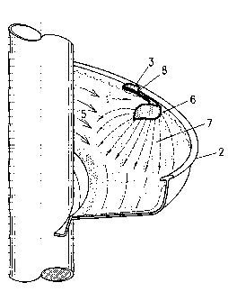
As shown in the drawings, the deflector, generally designated by the numeral
l, is
adapted to be attached to a spiral separator, generally designated by the
numeral 2. The
deflector 1 is designed to capture and redirect a controlled portion of the
flowing stream of
material flowing through the spiral separator. The deflector l, generally
includes an
attachment means 3, for attachment of the deflector 1 to the spiral separator
2, a capturing
portion 4 shaped to substantially ride atop and capture a portion of the
flowing stream of
material 5, and a redirecting portion 6, which is integrally formed with the
capturing
CA 02447527 2003-11-14
WO 02/092232 PCT/AU02/00602
-5-
portion 4, and which is shaped to spray or otherwise emit the captured
material, as
illustrated by reference numeral 7. The spray 7 may be patterned to be of any
desired
shape, depending upon the desired pattern of the spray as it re-enters the
main stream. For
example, the spray may be fan-shaped, substantially hemispherical in shape, or
any other
thin broad canopy of spray such that it re-enters the main stream
substantially in an arc
about the head of the reflector.
Other than the attachment means 3 being used to affix the deflector 1 to the
side of
the spiral separator 2, the attachment means 3 may incorporate an arm member
12, to
permit substantially resilient and/or pivotal movement of the deflector 1 when
connected to
the spiral separator 2. The arm member 12 may include any one or combination
of a
pivoting arm, a flexible arm, a string, line, flap, magnetic field, or any
other mechanical
means. Other forms of arm member may alternatively become apparent to persons
skilled
in the art and should be considered to be encompassed within the scope of this
invention.
The capturing portion 4 of the deflector 1, is shown in the drawings as
capturing
the "tailings" portion of the flowing stream of material 5 from an outer
region ID of the
trough 11 of the spiral separator 2.
As will be understood by persons skilled in the art, and as shown in Fig.
3(b), spiral
separators are generally used to recover minerals, and function by separating
materials in
to three generally lmown streams, including the 'concentrate' 8 found at the
inner edge of
the trough 11 of a spiral separator 2 and which is formed of particles of
higher specific
gravity, a 'tailing' stream 10 which is found towards the outer part of the
trough 11 being
the particles of lower specific gravity, and the 'middlings' stream 9 which is
found
intermediate the concentrate and tailings in the central transition zone.
As such, it will be appreciated that the deflector 1 shown in the drawings,
redirects
the portion of the material from the 'tailings' stream 10 in to the
'middlings' 9 portion of the
flowing stream 5. It is also shown in the drawings that this is redirected in
a fan like spray
manner.
By redirecting the material in this manner, the 'middlings' 9 stream is
exposed to
two gentle influences, firstly as it enters the fan upstream, and again when
it emerges
downstream. Such an effect provides a significant performance enhancement of
the spiral
separator.
CA 02447527 2003-11-14
WO 02/092232 PCT/AU02/00602
-6-
In an alternative arrangement, the redirecting portion, could redirect the
captured
material to another device (not shown), such as, but not limited to, a gallery
or distributor
to administer the water in a controlled manner.
The deflector device 2 of the present invention may either be at least partly
formed
from substantially buoyant material and/or, can be shaped to function in a
substantially
buoyant manner, then being formed of any desirable material. The device may be
weighted or tensioned for heavier action (heavier fan), or unweighted for
lighter action by
adjusting the flexibility, weight, tension or tightness of the arm member
portion of the
device, or by other means. Depending on the particular amount of capture
desired, these
attributes can be selectively varied such that it either substantially'rides'
or'aquaplanes' the
surface of the stream due to the pressure, velocity of the liquid, or, it can
be submerged to a
greater or lesser extent.
The device may also be twisted or pivotally adjusted to enable adjustment of
the
rate and/or format of the emission of the captured material.
The arm member may also be lengthened or shortened to change the angle and/or
the weighting in which the capturing portion penetrates the stream.
It will be appreciated that the present invention therefore provides a
deflector
device which is novel and inventive over the known prior art, including the
Applicant's
prior Australian Patent No. 575046 (27077/84). The differences and advantages
of the
device of the present invention is at least partially due to the freedom of
movement of the
device, whereby the head of the device floats or "rides" on top of the
'tailing' stream where
it captures and redirects a controlled quantity of the flow in to another
region of the trough.
As described, usually, the redirected flow would typically take the form of a
gentle fan or
other patterned spray, and the fan or spray is usually directed in to
the'middlings' stream.
The head of the device is buoyant, created either by the material and/or by
hydraulic pressure, to remain skimming the surface of the stream regardless of
the flow
rate of the spiral feed. The deflector therefore always remains in position
for optimal
performance. When the flow rate on a spiral increased, the stream at the outer
wall rises.
Tlus causes conventional deflectors with fixed position, such as described in
the
Applicant's earlier Australian Patent No. 575046 (27077/84) to become more
violent in it's
action, causing excessive disruption of the flow. When the flow rate on a
spiral decreased,
CA 02447527 2003-11-14
WO 02/092232 PCT/AU02/00602
the level of the stream falls. This reduces the influence of prior art
deflectors, and in some
cases, the stream may fall completely below the point where the deflector is
attached.
It will be appreciated that numerous variations and modifications may be
envisaged
by persons skilled in the art to the device hereinbefore described. All such
variations and
modifications should be considered to fall within the scope of the invention
as broadly
herein described and as hereinafter claimed.