Note: Descriptions are shown in the official language in which they were submitted.
CA 02447755 2003-11-03
ELECTRICAL OUTLET BOX
FIELD OF THE INVENTION
The present invention relates to an outlet box, more specifically to an
electrical outlet box for providing a housing for wiring connection.
BACKGROUND OF THE INVENTION
Electrical outlet boxes are commonly used for connecting various wires at a
fixed location or for attaching a fixture such as a light switch or other type
of switch
or mechanism to electrical wires routed throughout a building. Outlet boxes
are
typically attached to a wood or metal wall stud. The outlet box must be
properly
positioned in relation to the stud itself and the outer covering which is
later placed
over the stud. Typically, the outer covering placed on the stud is a gypsum
board
material, therefore, the outlet box must be positioned so that it is properly
recessed
within the outer covering to allow for the outlet box to be accessed. Outlet
boxes of
the prior art can be in the shape of a rectangular box which has an opening
positioned
adjacent the stud so that the outer covering to the wall can have an aperture
cut within
it so that the inside of the outlet box can be accessed.
Outlet boxes are subjected to various forces such as when an electrical plug
outlet is housed in the outlet box. The force of inserting and removing a plug
from
the plug outlet subjects the outlet box to various torque forces such that the
box must
be properly secured to resist inadvertent removal of the outlet box from the
stud.
Prior designs typically use at least two fasteners, such as a screw or a nail,
which are
inserted through openings in the sidewall of the outlet box so that the outlet
box can
be attached to the stud.
A problem associated with prior design is that in order to properly position
the
outlet box and attach it to a stud the user must insert two fasteners. During
the
construction of a building or residence many outlet boxes may have to be
installed.
The process of using these two fasteners is both time consuming and expensive
as it is
difficult to properly position the two fasteners to hold the box in place.
CA 02447755 2003-11-03
An example of one such outlet box is United States laatent No. 5,579,939 to
Bourassa which shows an outlet box that requires two fasteners to it to a
stud. The
outlet box of Bourassa shows that a set of first tabs 52 are used to position
the box on
the resting plane of the stud and a second pair of sharp tabs 54 are used to
penetrate
the side of the stud. However the Bourassa box utilizes the holes adjacent the
tabs 52
or tabs 54 to secure the box to the stud. The problem associated with this
design is
that multiple fasteners are needed to secure the box to the stud. The
fasteners are
positioned directly adjacent the tabs 52 or 54 and still allow for pivotal
movement of
the box about the tabs 52 or 54 if less than two fasteners are used.
One problem associated with this two fastener method is that it takes a
skillful
worker to properly position one fastener and then position a second fastener
so that
the outlet box does not pivot around the first fastener. This process is also
expensive
as buildings typically require hundreds of these outlet boxes to be installed
by an
electrician having relatively high labor costs. Accordingly, the ability to
reduce the
l 5 time associated with mounting these boxes is highly desirable.
Accordingly, it would be desirable to provide an outlet box which facilitates
the attachment of the box to a stud. There is also a further need for an
outlet box
which assists the user in properly positioning the outlet for attachment so
that the time
associated with installing the outlet box is shorter and more cost efficient.
SLfNYMARY OF THE INVENTION
The present invention is an electrical outlet box having a rear wall
parametrically bound by an orthogonally extending sidewall terminating at a
rim
defining an opening and an interior to the outlet box. The sidewall includes a
generally planar mounting surface adapted to be abutted against a structural
support,
such as a wall stud. The mounting surface including an aperture centrally
disposed
between a pair of prongs that are securable within the support structure for
temporarily securing the outlet box thereto without the need for a fastener.
The
aperture is adapted to receive a fastener for operatively securing the outlet
box to the
support structure.
2
CA 02447755 2003-11-03
In a preferred embodiment the outlet box further includes a pair of
positioning
tabs extending from the mounting surface to assist in positioning the outlet
box in
relation to the structural support. The positioning tabs are aligned along a
first
longitudinal axis. The sidewall can include a raised portion to form the
mounting
surface where the holding prongs extend therefrom and are pointed to assist in
piercing an outer surface of the structural support. The holding prongs are
aligned
along a second longitudinal axis of the mounting surface and are spaced a
distance
away from the positioning tabs. The aperture can be located equidistant from
each of
the prongs and the prongs are aligned in a substantially first linear axis and
the
aperture is positioned a distance away from the fast linear axis in a
substantially
parallel second axis.
An advantage of the present design is that only one fastener is needed to hold
the outlet box onto a stud, thus, eliminating the excess time and materials
needed.
A further advantage of the present invention is that the positioning tabs
assist
in positioning the outlet box in relation to the stud, thus, less training is
needed to
mount the box.
A still further advantage of the present invention is that the holding prongs
temporarily hold the outlet box in place while the user operatively affixes
the box to
the stud
A preferred form of the outlet box, as well as other embodiments, objects,
features and advantages of the present invention will be apparent from the
following
detailed description of illustrative embodiments thereof, which will be in
conjunction
with the acconnpanying drawings.
BRIEF DESCRIPTION OF THE DRAWINGS
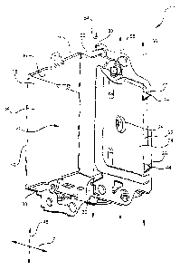
Fig. 1 is a side perspective view of the outlet box of the present invention;
Fig. 2 is a side elevational view of the outlet box of Fig. 1;
Fig. 3 is a partial perspective view of a holding prong of the outlet box as
shown in Fig. l;
3
CA 02447755 2003-11-03
Fig. 4 is an exploded perspective view of the outlet box of the present
invention attached to a stud;
Fig. 5 is a perspective view of the outlet box of the present invention
attached
to a stud; and
Fig. 6 is a partial cross sectional view of the outlet box of the present
invention
as shown in Fig. S taken along Line 6-6.
DETAILED DESCRIPTION OF THE PREFERRED EMBODIMENT
The outlet box 10 of the present invention provides a housing for electrical
wiring termination and electrical outlets and switches. The housing is able to
be
easily securable to a structural support 8, such as a stud, and allows for the
quick and
efficient attachment of the outlet box 10.
Referring to Figures 1-6, outlet box 10 has a rear wall 12 parametrica.lly
bound
by an orthogonally extending sidewall 14 terminating at a rim 16 that defines
an
opening 18 in the outlet box 10. The sidewall 14 and rear wall 12 form an
interior 20
to the outlet box 10. The outlet box 10 further includes a mounting surface 22
on the
sidewall 14 that is generally planar and is adapted to abut against a
structural support
8. Mounting surface 22 can include a pair of prongs 26 that are securable
within the
structural support 8 for temporarily holding the outlet box 10 to the
structural support
8. There is also an aperture 28 centrally disposed between the prongs 26 that
is
adapted to receive a fastener 46 for operatively securing the outlet box 10 to
the
structural support 8.
In a preferred embodiment, the sidewall l4 is divided up into four individual
sidewalk to form a rectangular box, however, it is envisioned that any shape
outlet
box 10 can be configured. A first wall 32 extends from the rear wall 12 and
has an
oppositely positioned and substantially parallel second wall 34. A third wall
36
connects the first wall 32 and second wall 34 and is substantially
perpendicular to the
first wall 32 and second wall 34. An oppositely positioned fourth wall 38
connects
the first wall 32 and second wall 34. The outlet box 10 can be made of a metal
such
as steel, however, it is also possible that a high strength plastic can also
be used.
4
CA 02447755 2003-11-03
Referring specifically to Figures l and 2, first wall 32 has at least one
positioning tab 30 extending substantially perpendicularly therefrom. In a
preferred
embodiment there are two positioning tabs 30 which may be rectangular shaped.
The
positioning tabs 30 assist in positioning the outlet box 10 on the structural
support 8.
The positioning tabs 30 are preferably linearly aligned along a first
longitudinally
extending axis 54 on the outlet box 10 to allow the opening I 8 of the outlet
box 10 to
be placed in the proper position in relation to the stud 8. When positioning
tabs 30 are
placed on the front face 40 of the stud, the outlet box opening 18 is
positioned such
that the outlet box rim 16 will project through the outer wall covering when
the outer
wall covering is placed over the stud 8. The outer wall covering can be a
material
such as gypsum board so that the outlet box 10 will project therethrough. The
positioning tabs 30 permit an installer to correctly position and align the
outlet box 10
in relation to the stud 8.
Sidewall 14 has a mounting surface 22 that abuts against the stud 8 when the
outlet box IO is mounted thereto. Referring to Figures 1-5 the mounting
surface 22
can be disposed on the first wall 32. First wall 32 has a raised portion 24
forming the
mounting surface 22 that can be a stamped or a drawn portion of first wall 32.
The
raised portion 24 can be used to allow the outlet box opening 18 to be
positioned a
distance D 1 away from the stud 8 and allows for a larger interior 20 of
outlet box 10
to facilitate use. The outer surface 60 of the raised portion 24 preferably
contacts the
side surface 42 of the stud 8. The raised portion 24 can include at least one
holding
prong 26 therefrom The raised portion 24 preferably has a longitudinal axis 48
and a
perpendicular lateral axis 50. As shown in Figures 1-5, the raised portion 24
is shown
to have a rectangular shape, however, it is envisioned that any shape raised
portion 24
can be used, such as a square.
In order to quickly and operatively secure the outlet box 10 to the structural
support 8, the outlet box 10 includes a mounting aperture 28 or hole. The
holding
prongs 26 temporarily hold the outlet box 10 in place while the user decides
on the
final positioning of the outlet box 10 on the structural support 8. In the
preferred
embodiment there are two holding prongs 26 extending from the mounting surface
22.
Referring back to Figure 3, holding prongs 26 have pointed tips 44 which are
used to
5
CA 02447755 2003-11-03
pierce a wood stud 8. The holding prongs 26 can be aligned along a second
longitudinal axis 56 on the mounting surface 22 and spaced a distance from
each other
on substantially the same linear axis. In a preferred embodiment (not shown),
the
holding prongs 26 are positioned at opposite corners of the raised portion 24
adjacent
the rear wall 12.
The outlet box 10 further includes an aperture 28 that is generally centrally
disposed between the pair of holding prongs 26. The aperture 28 can also be
positioned a distance away from the holding prongs 26 in a substantially
parallel
second axis. The aperture 28 can be positioned on a third longitudinal axis 58
on the
mounting surface 22 that is positioned between the first longitudinal axis 54
of the
positioning tabs 30 and the second longitudinal axis 56 of the holding prongs
26. In
the preferred embodiment the aperture 28 is positioned equidistant between the
pair of
holding prongs 26.
An advantage to the positioning of this particular fastening configuration is
that after the prongs 26 are forced to pierce the stud 8, a fastener 46 that
projects
through the aperture 28 forms a three-point attachment or a triangular shaped
attachment for the outlet box 10 to be held onto the stud 8. A further
advantage to
using the centrally located aperture 28 that is spaced a distance from the
linear axis of
holding prongs 26 is that the possibility of unwanted pivoting of the outlet
box 10
about the aperture 28 is prevented by the holding prongs 26.
Refernng to Figures 5 and 6, in order to mount the box, the user may first
align the positioning tabs 30 so that they are flush with the front face of
the stud 40
which can be made of wood. The tabs 30 are positioned flush so that the outlet
box
opening 18 projects outwardly from the front surface 40 so that a wall
covering can be
placed over the outlet box opening 18 and a hole can be cut so that the upper
rim 16
can project through the wall covering. The user then positions the mounting
surface
22 so that it abuts the side surface of the stud 42.
After the outlet box 10 is positioned, the user taps the opposite side of the
outlet box 10 so that the holding prongs 26 which project out of the raised
portion 24
of the outlet box 10 are then forced to pierce the outer surface of the stud.
The action
CA 02447755 2003-11-03
of piercing the outer portion of the stud is done so that the holding prongs
26
frictionally engage the wood stud 8. The outlet box 10 is now held in place by
the
two holding prongs 26. The user then has both hands available to insert a
fastener 46,
such as a screw or a nail, through the aperture 28 to operatively secure the
outlet box
into place. The outlet box 10 is held onto the stud by both holding prongs 26
which prevent pivoting of the outlet box 10 about the aperture 28 and the
fastener 46.
The outlet box 10 is further prevented from moving by the two positioning tabs
30
which are adjacent the front face of the stud 40 and prevents movement of the
box 10
in a pivoting manner about the fastener 46.
10 Although, holding prongs 26 hold the outlet box 10 to the stud, the
fastener 46
is used so that the outlet box is operatively or permanently secured to the
stud. The
use of a fastener 46 allows the outlet box to be held securely on the stud so
that it can
retain fixtures, such as switches, and not inadvertently be removed from the
stud
during use of the fixture.
As shown in Figure 6, only one fastener 46 is needed to hold the outlet box 10
in place, thus reducing the amount of time it takes to attach the outlet box
10. In
addition, the use of the positioning tabs 30 and the holding prongs 26 makes
it easy
for one who is not familiar with the positioning of the outlet box 10 to
properly
position the outlet box 10 onto a stud 8 without extensive training or
measuring. The
use of one screw when used in connection with the pair of holding prongs 26
have
been found to properly hold the outlet box 10 onto a stud to pass CSA 10
standard
without the need for additional fasteners 46. Less hardware and time is needed
to
properly attach the outlet box 10 thus reducing the cost and time associated
with
mounting the outlet box 10 securely.
Although preferred embodiments of the present invention have been described
herein with reference to the accompanying drawings, it is to be understood
that the
invention is not limited to those precise embodiments and the various other
changes
and modifications may be effected herein by one skilled in the art without
departing
from the scope or spirit of the invention, and that it is intended to claim
all such
changes and modifications that fall within the scope of the invention.
7