Language selection

Search

Patent 2448105 Summary

Third-party information liability

Some of the information on this Web page has been provided by external sources. The Government of Canada is not responsible for the accuracy, reliability or currency of the information supplied by external sources. Users wishing to rely upon this information should consult directly with the source of the information. Content provided by external sources is not subject to official languages, privacy and accessibility requirements.

Claims and Abstract availability

Any discrepancies in the text and image of the Claims and Abstract are due to differing posting times. Text of the Claims and Abstract are posted:

  • At the time the application is open to public inspection;
  • At the time of issue of the patent (grant).
(12) Patent Application: (11) CA 2448105
(54) English Title: DEVICE FOR DETACHING A PAPER WEB FROM A WIRE
(54) French Title: DISPOSITIF POUR LE DEGAGEMENT D'UNE FEUILLE DE PAPIER CONTINUE D'UNE TABLE DE FABRICATION
Status: Deemed Abandoned and Beyond the Period of Reinstatement - Pending Response to Notice of Disregarded Communication
Bibliographic Data
(51) International Patent Classification (IPC):
  • D21F 07/04 (2006.01)
  • D21F 02/00 (2006.01)
  • D21F 07/00 (2006.01)
  • D21F 09/00 (2006.01)
(72) Inventors :
  • WEIGANT, HARALD (Austria)
(73) Owners :
  • ANDRITZ AG
(71) Applicants :
  • ANDRITZ AG (Austria)
(74) Agent: MARKS & CLERK
(74) Associate agent:
(45) Issued:
(22) Filed Date: 2003-11-04
(41) Open to Public Inspection: 2004-05-11
Examination requested: 2008-01-03
Availability of licence: N/A
Dedicated to the Public: N/A
(25) Language of filing: English

Patent Cooperation Treaty (PCT): No

(30) Application Priority Data:
Application No. Country/Territory Date
A 1692/2002 (Austria) 2002-11-11

Abstracts

English Abstract


The invention relates to a device for detaching a paper web 9 from a wire
4, where the pulp suspension is fed in between a wire 4 and a felt 5 by a
headbox 2, the wire 4 and felt 5 are guided together over a forming roll 3,
and are separated from one another after the web 9 has formed. It is
especially characterised by the separation point 10 of wire 4 and felt 5
being located at a distance from the forming roll 3.


Claims

Note: Claims are shown in the official language in which they were submitted.

Claims
1. Device for detaching a paper web from a wire, where the pulp
suspension is fed in between a wire and a felt by a headbox, the wire
and felt are guided together over a forming roll, and are separated
from one another after the web has formed, characterised by the
separation point (10) of wire (4) and felt (5) being located at a distance
from the forming roll (3).
2. Device according to Claim 1, characterised by the separation point (10)
being designed as a suction roll (15) with vacuum chamber (16).
3. Device according to Claim 1, characterised by the separation point (10)
being designed as a suction shoe (11).
4. Device according to Claim 3, characterised by suction shoe (11) having
one, advantageously several, particularly two suction slots (14).
5. Device according to one of Claims 1 to 4, characterised by at least one
web cutting device (12), particularly a movable cutting device, in
particular edge trim nozzle(s) or tail cutter nozzle(s), being provided at
the separation point (10) of wire (4) and felt (5).
6. Device according to one of Claims 1 to 4, characterised by at least one
web cutting device (12), particularly a movable cutting device, in
particular edge trim nozzle(s) or tail cutter nozzle(s), being provided
between the forming roll (3) and the separation point (10) of wire (4)
and felt (5).
7. Device according to Claim 5 or 6, characterised by a device with one or
several nozzles being provided to cut the feed strip to the paper
machine.
4

Description

Note: Descriptions are shown in the official language in which they were submitted.


CA 02448105 2003-11-04
The invention relates to a device for detaching a paper web from a wire,
where the pulp suspension is fed in between a wire and a felt by a
headbox, the wire and felt are guided together over a forming roll, and are
separated from one another after the web has formed.
A device of this kind is described, for example in US 5,908,534. When
they leave the roll, the wire and felt are separated from one another, while
the paper web remains on the felt and is then brought to the drying plant.
The disadvantage of the arrangement is that the felt sags after being
separated from the wire, particularly at high machine speeds or large web
widths, thus causing damage to the web. Also, the paper web is not
always detached entirety from the wire. This causes clogging of the wire
on the one hand, and repeated sheet breaks on the other.
The invention now aims to correct the disadvantage of state-of the-art
plants and achieve exact detaching, even at relatively low felt tension and
large machine widths and/or high machine speeds, while retaining the
high quality of the paper web.
This is achieved according to the invention by locating the separation point
of wire and felt at a distance from the forming roll. As a result, optimum
felt tension can always be achieved at the same time as exact web
2o detaching.
It is an advantage if the separation point is designed as a suction roll with
vacuum chamber, however it can also be designed as a suction shoe.
In an embodiment with a suction shoe, it has proved favourable if the
suction shoe has one, advantageously several, particularly two suction
slots.
If at feast one web cutting device, particularly a movable cutting device, in
particular edge trim nozzles) or tail cutter nozzle(s), is (are) provided in
addition at the separation point of wire and felt, exact cutting can be
achieved at the same time without influencing formation of the web. The
2462

CA 02448105 2003-11-04
web cutting device can also be located adjacent to the web between the
forming roll and the separation point of wire and felt. In this case, the web
cutting device can be designed such as to be movable in machine running
~r in cross-machine direction.
The invention will now be described using the examples in the drawings,
where Fig. 1 shows a state-of-the-art plant, Fig. 2 shows a plant
containing the device according to the invention and Fig. 3 provides a cut-
out from Fig. 2, Fig. 4 shows a detail from Fig. 3, and Fig. 5 illustrates an
alternative embodiment of the invention.
Figure 1 shows a cut-out from the wet section of a paper machine, for
production of tissue grades for example. The wet section comprises a
twin wire former 1 and a headbox 2. The twin wire former 1 is shown as a
crescent former with a forming roll 3, a wire 4, and a felt 5. The wire 4 and
felt 5 are run together over the forming roll 3. The wire 4 is guided over a
breast roll 6 and, after separation, aver a guide roll 7 located a short
distance from the forming roll 3. After separation from the wire 4, the felt
5 is guided over a roil 8 together with the paper web 9 formed. In this type
of plant, there is a risk at low felt tension, high speeds or large machine
widths of frequent felt 5 sagging, thus causing uneven contact with the
2o wire 4, which leads to damage to the paper web or also to web breaks.
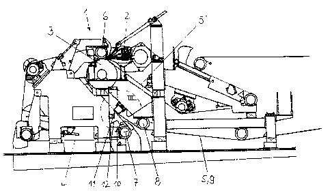
In Fig. 2, a plant is illustrated with the device according to the invention,
where corresponding parts are marked with the same references as in
Fig. 1. Unlike the state of the art, the wire 4, felt 5 and the paper web 9
between the two are still together here when they leave the forming roll
and continue some distance together. They do not separate until they
reach the separating point 10. As a result, the circumference of the
forming roll can be utilised for longer or the same forming times can be
achieved at higher machine speeds, which means that the quality of the
paper web is also retained at higher machine speeds. At the separation
3o point 10, a suction shoe 11 is provided in this illustration. In addition,
2462

CA 02448105 2003-11-04
showers 12 for high-pressure water are shown for cutting the edge trim
and feed strip.
Figure 3 shows a cut-out from Fig. 2 marked there with a circle III. Here,
the separating point 10 is clearly visible. The wire 4 continues over a
deflection roll 7, while felt 5 and paper web 9 are carried onwards over a
deflection roll 8. The suction shoe 11 is connected to a suction pipe 13
and to openings 14, particularly a slot provided across the web running
direction. If the edge trim or the feed strip is to be cut here, nozzles 12
are used with their jet directed into the slot 14 to prevent wetting the paper
web 9 in any way and to carry off the water effectively. The jet can also
be aimed at a point ahead of the slot 14. Of course, it would also be
possible to provide two suction slots 14 one behind the other, which is
particularly effective in separating removal of the spraying water by
suction from adherence of the paper web by suction to the felt.
Figure 4 shows the separating point 10 once again in detail. Here the slot
14 in the suction shoe 11 is particularly clear.
Figure 5 illustrates an alternative embodiment of the invention. Instead of
the suction shoe, a suction roll 15 with a vacuum chamber 16 is used
here. The advantage of this variant is the means of applying a vacuum to
2o the felt, and thus also to the paper web, for a longer period. As a result,
reliability of transfer of the paper web to the felt is enhanced even further.
The invention is not limited to the configurations illustrated. Thus, the high-
pressure jet can also be mounted on a movable device as a so-called tail
cutter in order to provide a strip for feeding the paper web into the paper
machine, where the strip then broadens to cover the entire web width.
Here, too, it would be feasible to use devices similar to the suction roll or
suction shoe for detaching purposes.
2462

Representative Drawing
A single figure which represents the drawing illustrating the invention.
Administrative Status

2024-08-01:As part of the Next Generation Patents (NGP) transition, the Canadian Patents Database (CPD) now contains a more detailed Event History, which replicates the Event Log of our new back-office solution.

Please note that "Inactive:" events refers to events no longer in use in our new back-office solution.

For a clearer understanding of the status of the application/patent presented on this page, the site Disclaimer , as well as the definitions for Patent , Event History , Maintenance Fee  and Payment History  should be consulted.

Event History

Description Date
Application Not Reinstated by Deadline 2011-02-28
Inactive: Dead - No reply to s.30(2) Rules requisition 2011-02-28
Deemed Abandoned - Failure to Respond to Maintenance Fee Notice 2010-11-04
Inactive: Abandoned - No reply to s.30(2) Rules requisition 2010-03-01
Inactive: S.30(2) Rules - Examiner requisition 2009-08-28
Letter Sent 2008-03-04
Request for Examination Received 2008-01-03
Amendment Received - Voluntary Amendment 2008-01-03
All Requirements for Examination Determined Compliant 2008-01-03
Request for Examination Requirements Determined Compliant 2008-01-03
Inactive: IPC from MCD 2006-03-12
Application Published (Open to Public Inspection) 2004-05-11
Inactive: Cover page published 2004-05-10
Inactive: First IPC assigned 2004-01-02
Inactive: Filing certificate - No RFE (English) 2003-12-10
Letter Sent 2003-12-10
Application Received - Regular National 2003-12-10

Abandonment History

Abandonment Date Reason Reinstatement Date
2010-11-04

Maintenance Fee

The last payment was received on 2009-10-26

Note : If the full payment has not been received on or before the date indicated, a further fee may be required which may be one of the following

  • the reinstatement fee;
  • the late payment fee; or
  • additional fee to reverse deemed expiry.

Patent fees are adjusted on the 1st of January every year. The amounts above are the current amounts if received by December 31 of the current year.
Please refer to the CIPO Patent Fees web page to see all current fee amounts.

Fee History

Fee Type Anniversary Year Due Date Paid Date
Application fee - standard 2003-11-04
Registration of a document 2003-11-04
MF (application, 2nd anniv.) - standard 02 2005-11-04 2005-10-24
MF (application, 3rd anniv.) - standard 03 2006-11-06 2006-10-23
MF (application, 4th anniv.) - standard 04 2007-11-05 2007-10-24
Request for examination - standard 2008-01-03
MF (application, 5th anniv.) - standard 05 2008-11-04 2008-10-27
MF (application, 6th anniv.) - standard 06 2009-11-04 2009-10-26
Owners on Record

Note: Records showing the ownership history in alphabetical order.

Current Owners on Record
ANDRITZ AG
Past Owners on Record
HARALD WEIGANT
Past Owners that do not appear in the "Owners on Record" listing will appear in other documentation within the application.
Documents

To view selected files, please enter reCAPTCHA code :


To view images, click a link in the Document Description column. To download the documents, select one or more checkboxes in the first column and then click the "Download Selected in PDF format (Zip Archive)" or the "Download Selected as Single PDF" button.

List of published and non-published patent-specific documents on the CPD .

If you have any difficulty accessing content, you can call the Client Service Centre at 1-866-997-1936 or send them an e-mail at CIPO Client Service Centre.


Document
Description 
Date
(yyyy-mm-dd) 
Number of pages   Size of Image (KB) 
Description 2003-11-03 3 159
Abstract 2003-11-03 1 13
Claims 2003-11-03 1 41
Drawings 2003-11-03 5 123
Representative drawing 2004-04-13 1 26
Claims 2008-01-02 2 66
Description 2008-01-02 4 192
Courtesy - Certificate of registration (related document(s)) 2003-12-09 1 125
Filing Certificate (English) 2003-12-09 1 169
Reminder of maintenance fee due 2005-07-04 1 109
Acknowledgement of Request for Examination 2008-03-03 1 177
Courtesy - Abandonment Letter (R30(2)) 2010-05-24 1 164
Courtesy - Abandonment Letter (Maintenance Fee) 2010-12-29 1 173