Note: Descriptions are shown in the official language in which they were submitted.
CA 02448334 2003-11-03
SIGN LANGUAGE EDUCATIONAL DOLL
1. TECHNICAL FIELD
The present invention relates generally to electronic devices which teach or
demonstrate sign
language. The present invention relates specifically to a doll that serves as
a means for teaching sign
language both visually and audibly.
2. BACKGROUND OF THE INVENTION
Technology relating to communication with sign language may be divided into
three major
areas: educational devices used to teach sign language; systems that provide a
means for inputting
data into a computer using sign language; and devices that receive input from
a computer keyboard
then demonstrate sign language using some form of hand.
Educational Devices
U.S. Pat. No. 4,378,215 ("215") to Sparks discloses an educational apparatus
for teaching the
American Manual Alphabet ("AMA") to individuals, especially to the blind
and/or deaf. The
apparatus consists of a plurality of three-dimensional moulded figures of the
human hand mounted
on a base and each formed in a respective letter of the AMA. A disadvantage of
the '215 apparatus
is that the apparatus can only demonstrate the fmal hand positions of the AMA
letters and not the
required interim movements. A further disadvantage is that the '215 apparatus
is limited to visual
demonstration of the AMA. Finally, the apparatus is not engaging for children
and therefore has
limited educational potential.
U.S. Pat. No. 4,799,889 to Yockey discloses a stuffed bear for teaching sign
language to deaf
children. The stuffed bear utilizes a pair of hollow tubular arms through
which the arms of a teacher
pass, so that the hands project beyond the front edge surface of each arm. The
complete articulation
of the arm may be achieved to allow for the signs of sign language to be
performed. This doll
requires a skilled operator in AMA to manipulate the doll and provide
educational value.
1
CA 02448334 2003-11-03
U.S. Pat. No. 4,878,843 to Kuch discloses a process and an apparatus for a
system of
animation and a system of teaching finger spelling. The Kuch patent :is
limited to providing visual
images of hands which demonstrate finger positions and does not provide a
physical hand that can
be looked at and touched and so is uninteresting to children.
Systems for Inputting Data and Translating Sign Language
U.K. Pat. No. 2,302,583 ("583") to Klein et al. discloses gloves and a hand
tapper for
communicating with deaf-blind people. The '583 patent teaches that words can
be entered into a
computer character by character using sign language read via a pair of gloves
having electrodes
disposed on their surfaces worn by the operator. Circuitry is used to uniquely
identify the hand sign
being made, and a hand tapper reads out the signs for a deaf-blind individual.
U.S. Pat. No. 5,047,952 to Kramer et al. discloses a communication system for
deaf, deaf-
blind, or non-vocal individuals using an instrumented glove for obtaining
electrical signals
indicative of a hand configuration of the individual. These electrical signals
are processed and
applied to a computer which subsequently outputs to a second individual. The
output means
depends upon the visual, vocal and hearing capabilities of the individuals but
could comprise a voice
synthesizer, LCD monitor, or Braille display.
U.S. Pat. App. No. US 2002/0152077 Al to Patterson discloses a method and
apparatus for
translation of hand positions into symbols. The invention comprises a glove
for detecting the
configuration of an individual's hand and an output device that produces
either a visual or audio
output corresponding to the hand position.
The above data input systems are limited to taking sign language as input;
they do not
demonstrate or teach how to perform the finger movements of sign language.
Devices Which Receive Input From a Keyboard
U.S. Pat. No. 4,074,444 ("444") to Laenger, Sr. et al. discloses a method and
apparatus for
2
CA 02448334 2003-11-03
communicating with deaf-blind individuals. The apparatus comprises a keyboard
controlled
electromechanical arm. The electromechanical arm is programmed to form the
letters of the
standard one-hand manual alphabet through the use of an electronic buffer
between the electric
typewriter and the electromechanical arm. Deaf and/or deaf-blind individuals
feel or observe the
configuration of the electromechanical arm and are able to identify the
letters being typed on the
keyboard.
The '444 patent discloses an electromechanical arm that is mounted on a
controlling means.
Such a design is not suitable or convenient for a doll. Further, the hand in
the '444 patent consists
of cable-pulled fingers, which is impractical in a doll. The disclosure that
the electromechanical arm
can not effectively demonstrate the more complicated hand movements required
for letters such as J
or Z. Finally, the controlling means requires input from the typewriter means,
and it cannot operate
autonomously.
The manual alphabet can be found in Riekehof, The Joy of Signing, Gospel
Publishing
House, 1445 Boonville Ave., Springfield, Mo., p.15 (ISBN-0-88243-518-3).
Devices that communicate and teach sign language are not unique. There is,
however, a
need for a teaching apparatus which provides a physical hand and additional
educational aids to
teach people sign language in a fun and pedagogically sound manner.
3
CA 02448334 2003-11-03
3. SUMMARY OF THE INVENTION
An apparatus for a sign language element demonstrating doll comprising an
electromechanical
arm and hand positionally adjustable in a manner operative to demonstrate sign
language elements is
provided. Advantageously, the doll may further include an audio system for
vocalizing the verbal
equivalent of the sign language elements and a display system for displaying
the Latin alphabet
equivalent of the sign language elements. The audio and visual systems may
comprise a speaker
and a display screen which simultaneously broadcast and display the equivalent
of the sign language
elements which are being demonstrated by the doll.
Preferably the sign language elements are the American Manual Alphabet ("AMA")
signs
corresponding to the characters of the Latin alphabet. The electromechanical
hand displays the
AMA signs in sequence, while simultaneously broadcasting the equivalent name
of the sign in a
spoken language and displaying the Latin alphabet equivalent of the sign on
the display screen. The
sign language element may be a sign representing a single letter of an
alphabet, a word or a phrase.
Further, the doll for demonstrating sign language may comprise an
electromechanical arm
attached to a right shoulder having a forearm segment, a hand segment and
finger segments, an
electronic controller including circuit board, a processor, a memory and
interface headers, an
electronic display, an audio means, an electronic display screen, an audio
output and a power
supply.
Further advantageously, a hand of the doll is comprised of a plurality of
joints, springs and
solenoids such that when the solenoids are activated, the finger segments are
flexed about the
corresponding joint, and when the solenoids are deactivated, the springs
return the finger segments
to a neutral extended position. The doll may also comprise a wrist joint and
an elbow joint
including multi-position solenoids, operable in at least three positions.
The electronic display is may be an alphanumeric light emitting diode display,
and the audio
means may be a piezo-electric speaker. The processor may be a microcontroller,
and the power
4
CA 02448334 2003-11-03
supply may be a 6 volt rechargeable battery.
Advantageously the electromechanical hand may have a hand segment and finger
segments
for demonstrating sign language comprised of: four independently controllable
fingers with at least
one joint each and moveably attached to the hand segment by one joint; an
independently
controllable thumb with at least one joint and moveably attached to the hand
segment by one joint;
and
a controller having a processor and a memory and being attached to the hand.
The hand may
additionally comprise an electromechanical arm having a forearm segment, the
hand being
moveably attached at a distal end of the forearm segment, such that the
forearm segment is
moveable to demonstrate sign language.
Advantageously, the electronic display may be an alphanumeric light emitting
diode or a
backlit liquid crystal display attached to the electromechanical arm. The
audio output may be a
piezo-electric speaker. The memory may be an interchangeable memory card.
The doll may include at least one spring and at least one electric solenoid
disposed at each
joint wherein when the solenoids are activated, the segments are flexed and
wherein when the
solenoids are deactivated, the springs extend the segments to a neutral
anatomical position.
A method of sequentially demonstrating the hand and finger positions of the
American
Manual Alphabet using an electromechanical arm while concurrently displaying
the letter being
signed on a digital display and concurrently providing an audial
representation of the letter being
signed through an audio device is also disclosed. The method includes the
steps of: turning a switch
on the doll to an on position; controlling an electromechanical arm, hand, and
fingers to form a
physical representation of a sign language component and simultaneously
controlling an audio
output device to emit a sound corresponding to the sign language component;
and simultaneously
controlling a display device to show the Latin character corresponding to the
sign language
component.
A method of demonstrating sign language with a doll having an electronic
control device, an
audio output device, a visual display device and a plurality ofjoints
manipulatable by a flexional
CA 02448334 2003-11-03
device comprising the steps of: controlling the manipulatable joints in at
least one finger, and an
elbow and wrist of the doll to form a sign language; and simultaneously
emitting the sound
corresponding to the sign from the audio output device; and simultaneously
displaying the Latin
letter equivalent of the sign on the visual display device is disclosed.
Advantageously, the flexional devices are electrical solenoids, which may be
controlled to flex the
fingers, hand and wrist to form the sign character by deactivating the
solenoids then returning the
fingers, hand and wrist to a neutral position by means of at least one spring
under tension.
6
CA 02448334 2003-11-03
4. BRIEF DESCRIPTION OF THE DRAWINGS
The apparatus and method of the present invention will now be described with
reference to
the accompanying drawing figures, in which:
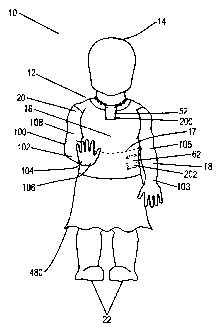
Figure 1 is a front view of the doll according to the invention.
Figure 2 is a rear view of the doll with the cavity in the open position,
according to the invention.
Figure 3 is a detailed top view of the electromechanical arm according to the
invention.
Figure 4 is a detailed top view of the plunger assembly according to the
invention.
Figure 5 is a detailed top view of the electromechanical hand according to the
invention.
Figure 6 is a detailed bottom view of the electromechanical hand according to
the invention.
Figure 7 is a diagramatic view of the controller board according to the
invention.
Figure 8 is a diagramatic view of a variation of the control section according
to the invention.
Figure 9 is a diagramatic view of a variation of the control section according
to the invention.
5. DETAILED DESCRIPTION OF THE PREFERRED EMBODIMENT
Figure 1 is a front view of a doll 10 which is a fun and educational learning
tool for children.
The doll 10 is an accessible educational tool from which all individuals,
regardless of physical
limitations, can learn. Blind individuals can learn sign language by feeling
the hand and listening to
the audible accompaniment. Deaf individuals can learn by observing the hand
position and the
corresponding letter being displayed on the electronic display. Individuals
without physical
limitations will benefit from three concurrent learning aids.
The preferred embodiment of the invention is a toy-like doll 10 that
demonstrates the finger
and hand movements of the American Manual Alphabet ("AMA"). The preferred
embodiment of
the invention teaches the AMA, and variations of the present invention teach
other forms of sign
language.
An advantage of the doll 10 is its form. An isolated hand is not as conducive
to learning for
7
CA 02448334 2003-11-03
children as the doll 10. The doll 10 presents the opportunity for a child to
form a bond with the doll
10, which has a far-reaching value for educating children.
The doll 10 is comprised of a body 12 with a head 14, torso 16, left arm 18,
hollow right
upper arm 20 and legs 22. In the preferred embodiment the body 12 is modelled
on a human child
and the height of the body 12, including the head 14, torso 16 and legs 22, is
between 68cm (28")
and 90cm (36"). Optimally, the doll 10 is approximately 73 and (30") in
length. The body 12 is
made of a human skin coloured toy-grade plastic such as polyurethane. Any
other material that has
equivalent strength and durability may be substituted.
The dol110 is covered by clothing such as a dress 480 which serves to make the
dol110 more
lifelike. The clothing 480 may be removed so that a child may dress and
undress the doll 10. A
variety of clothing 480 styles and types may be used to dress the doll 10.
An electronic letter display 52 is recessed in the upper left front chest area
of the torso 16 by
fasteners 200 which are preferably commercially available nuts and bolts. Any
other fastening
means such as screws may be used. In the preferred embodiment, the electronic
letter display 52 is
an alphanumeric such as Fairchild TM Semiconductor part number MSA5460C. Any
suitable
electronic letter display technology can be used, such as alphanumeric LED
(light emitting diode)
displays and LCD's (liquid crystal displays).
An audio output device 62 is recessed in the lower left front chest area of
the torso 16 by
fasteners 202 which are preferably commercially available nuts and bolts. Any
other fastening
means such as screws may be used. The audio output device 62 is preferably a
piezoelectric-type
speaker. Any such audio device, with sufficient dynamic range to reproduce
clearly the human
voice, specifically a frequency range of approximately 30Hz to 14kHz, can be
used. This includes,
for instance, a cone speaker.
An electromechanical arm subsystem 100, comprising a forearm 102, a hand 104,
and a skin
covering 108, is attached to the hollow right upper arm 20. The proximal end
of forearm 102 is
attached (the details of the attachment provided below) to the distal end of
the upper arm 20 and
fixed at an approximately 45 degree angle. The hand 104 is attached to the
forearm 102 (details of
8
CA 02448334 2006-09-15
attachment provided below). The arm subsystem 100 is positioned so that the
hand 104 is generally
above the waistline 17 of the doll 10 with the palm 106 facing generally
forward and in front of the
torso 16. This position is the most common signing position. The arm subsystem
100 is covered by
a skin covering 108 which serves to protect the components of the arm,
described below, and make
the doll 10 look more lifelike. The skin 108 must be flexible enough to allow
the fingers and wrist of
the hand 104 to move and bend. The skin 108 is preferably a human skin
coloured polyurethane
rubber. Other materials may be used such as silicon rubber; fur may be used to
make the doll look
like a teddy bear.
Referring now to Figure 2, a diagrammatic rear view of the doll 10 according
to the invention,
the torso 16 includes a cavity 24 that is disposed in the back area of the
torso 16. The cavity 24 is
generally shaped like an open cube or box. In the preferred embodiment, the
cavity 24 is
approximately 51mm (2") in depth, 102mm (4") in width and 102mm (4") in
height. The cavity 24 is
comprised of a back wal126, a top wall 28, a left wall 30 and a right wall 32.
A display opening 34 is
disposed in the upper area of the back wall 26 and provides access to the
backside of the display 52.
An audio opening 36 is disposed in the lower area of the back wall 26 and
provides access to the
backside of the audio device 62. An arm opening 38 is disposed in the top wall
28 and provides
access to the arm subsystem 100. A power switch opening 40 is disposed in the
lower area of the left
wall 30 and provides access to the backside of the power switch 192. The
display opening 34, audio
opening 36, arm opening 38 and power switch opening 40 are generally circular
and approximately
13mm (1/2") in diameter.
Access to the components contained in the cavity 24, for servicing and
maintenance, is
provided by a generally rectangular opening 42 disposed in the back area of
the torso 16. The
opening 42 is covered with a generally rectangular cover 44 shown here in the
open position. When
the cover 44 is closed, the opening 42 is completely covered by the cover 44
and damage to the
components contained in the cavity 24 is thereby prevented. The proximal edge
of the cover 44 is
attached to the body 12 by at least two hinges 46 and the distal edge of the
cover 44 is secured by a
cover fastener 204. The cover fastener 204 is preferably a commercially
available nut and bolt or
screw.
A controller 70 is attached to the upper portion of the back wall 26 by
fasteners 206 which
9
CA 02448334 2006-09-15
are preferably commercially available nuts and bolts. Any other fastening
means such as screws may
be used. The controller 70 is comprised of a circuit board 71, display header
80, audio header 82,
arm power header 84, arm control header 86, power switch header 88, and power
supply header 90.
The backside of the display 52 is connected by a plurality of display power
wires 462 and
display control wires 452 to the display header 80 through the display opening
34. The backside of
the audio output 62 is connected by a plurality of audio output wires 454 to
the audio header 82
through audio opening 36. A plurality of arm control wires 456 are connected
between arm
subsystem 100 and the arm control header 86 through arm opening 38. A
plurality of arm power
wires 464 are also connected between arm subsystem 100 and the arm power
header 84 through arm
opening 38.
A power switch 192 is recessed in the lower left rear area of the torso 16 by
switch fasteners
208 which are preferably commercially available nuts and bolts. Any other
fastening means such as
screws may be used. In the preferred embodiment the switch 192 is a
commercially available toggle
switch. Other switch types such as pushbutton switches may be used. The switch
192 is connected
to the power switch header 88 by a plurality of switch power wires 466.
A power supply 190 is attached to the lower portion of back wall 30 by
fasteners 210 which
are preferably commercially available nuts and bolts. Any other fastening
means such as screws may
be used. A plurality of controller power wires 468 are connected at one end to
the power supply 190
and at the other end to the power supply header 90. The power supply 190
preferably comprises a
rechargeable 6 volt battery. Other battery types may be used, such as standard
C cell or D cell
batteries. Alternatively, an AC-DC power supply may be used. In the preferred
embodiment 6 volts
direct current is used, but the voltage may increase or decrease for
variations of the doll 10.
All electric control wires 452 and 456 and electrical power wires 462, 464,
466 and 468 are
preferably tie-wrapped and attached to torso 16 at a multiplicity of plastic
clips moulded within torso
16 in a method common to the art.
Referring now to Figure 3, a detail, top view of the electromechanical arm,
generally referred
CA 02448334 2006-09-15
to by 100, is shown. The electromechanical arm 100 is a human-like arm that is
capable of
reproducing the finger and hand movements of the American Manual Alphabet. The
AMA is
inherently tolerant to inaccuracies in finger and hand position. Meaning is
not lost as long as fingers
are held in an approximate position representative of the correct AMA hand
position. Although the
arm subsystem 100 has been designed to accurately form the AMA hand positions,
some flexibility in
accuracy is permissible due to the typical and allowable variation of hand
position for the AMA.
The arm subsystem 100 is composed of a plurality of cylindrical segments. The
segments are
preferably constructed from polyethylene plastic, but may be constructed from
any other
commercially available light weight, rigid material such as aluminium metal.
Each segment is
connected by a joint which is preferably a ball and socket joint. In the
preferred embodiment the arm
subsystem 100 is preferably between approximately 18cm (7") and 22cm (9") in
length.
The arm subsystem 100 is comprised of a forearm segment 102, a hand 104, and
solenoids
132 and 134. The solenoids 132 and 134 are comprised of a housing 301 and a
plunger 302. The
housing 301 of the elbow solenoid 132 is attached to the left side of the
distal end of the hollow right
upper arm 20 by elbow solenoid fasteners 212 which are preferably commercially
available nuts and
bolts. The left side of the proximal end of the forearm segment 102 is
connected to the plunger 302
of the solenoid 132 by forearm fasteners 214. The forearm 102 is preferably
between approximately
10cm (4") and 13cm (5") in length. The housing 301 of the wrist solenoid 134
is attached to the
underside of the distal end of the forearm 102 by wrist solenoid fasteners 216
which are preferably
commercially available nuts and bolts. The proximal end of the hand 104 is
attached to the plunger
302 of the solenoid 134 by wrist fasteners 218. Both the solenoid 132 and 134
are preferably multi-
position solenoids and comprise a proximal end, and a distal end. The proximal
and distal ends
correspond to the proximal and distal end ends of the forearm segment 102.
The hand 104 is comprised of a plurality of cylindrical segments. The segments
are
preferably constructed from polyethylene plastic, but may be constructed from
any other
commercially available light weight, rigid material such as aluminium metal.
Each segment is
connected by a joint which is preferably a ball and socket joint, but may also
be connected using
tongue/groove/pin connections. In the preferred embodiment the hand 104 is
preferably between
11
CA 02448334 2003-11-03
approximately 8cm (3") and 10cm (4") in length.
The interconnection of the cylindrical segments will now be described. The
hand 104 is
comprised of a palm 106, a thumb 500, a first finger 502, a second finger 504,
a third finger 506 and
a fourth finger 508. The palm 106 is generally quadrilateral in shape and is
preferably constructed
from polyethylene plastic, but may be constructed from any other commercially
available
lightweight, rigid material such as aluminium metal.
The thumb 500 is comprised of a lower thumb segment 111 and an upper thumb
segment
112. The housing 301 of a first thumb solenoid 136 is attached to the left
side of the palm 106 by
thumb solenoid fasteners 220. The plunger 302 of solenoid 136 is connected to
the proximal end of
a lower thumb segment 111 by a thumb segment fastener 222. The distal end of
the lower thumb
segment 111 is connected to the proximal end of an upper thumb segment 112 by
a joint 352. The
first thumb solenoid 136 is preferably a commercially available multi-position
solenoid.
The first finger 502 is comprised of a first finger lower segment 113 and a
first finger upper
segment 114. The proximal end of a first finger lower segment 113 is connected
to the distal end of
the palm 106 by a joint 353. The distal end of first finger lower segment 113
is connected to the
proximal end of a first finger upper segment 114 by a joint 354.
The second finger 504 is comprised of a second finger lower segment 115 and a
second
finger upper segment 116. The proximal end of a second finger lower segment
115 is connected to
the distal end of the palm 106 by a joint 355. The distal end of second finger
lower segment 115 is
connected to the proximal end of a second finger upper segment 116 by a joint
356.
The third finger 506 is comprised of a third finger lower segment 117 and a
third finger
upper segment 118. The proximal end of a third finger lower segment 117 is
connected to the distal
end of the palm 106 by a joint 357. The distal end of third finger lower
segment 117 is connected to
the proximal end of a third finger upper segment 118 by a joint 358.
The fourth finger 508 is comprised of a fourth finger lower segment 119 and a
fourth finger
upper segment 120. The proximal end of a fourth finger lower segment 119 is
connected to the
12
CA 02448334 2006-09-15
distal end of the palm 106 by a joint 359. The distal end of the fourth finger
lower segment 119 is
connected to the proximal end of a fourth finger upper segment 120 by a joint
360.
Referring now to Figure 4, a top view of the preferred embodiment of the
solenoid plunger
fastening means 300 is shown. Note that the components are not shown to scale,
as indicated by the
break line in plunger 302. A solenoid 130 is comprised of a housing 301 and a
plunger 302. The
plunger 302 is connected internally within the housing 301. The distal end of
the plunger 302 is
preferably comprised of a metal fork 303 with a hole 304 there through. A rod
305 is inserted
transversely between the tines of the fork 303 and a pin 307 is inserted
through both the tines and the
rod 305. The rod 305 is inserted through a hole 308 in the finger segment 309
and a nut 306 is
attached to the opposite end of the rod 305 thereby retaining it to the finger
segment 309. The pin
307 is preferably a commercially available cotter pin. The nut 306 is
preferably a commercially
available nut. The rod 304 is preferably a commercially available bolt, with a
hole drilled through the
non-threaded end. The components such as the plunger 302, rod 305 and finger
segment 309 are not
shown to scale. The lengths of the components must be sized to permit flexion
and extension of the
finger segments.
Referring now to Figure 5, a top view of the preferred embodiment of the hand
104 is shown.
A plurality of springs and solenoids 130 are attached to certain locations on
the fingers 500-508 and
the hand 104. The solenoids 130 are comprised of a proximal end, and a distal
end. The proximal
and distal ends correspond to the proximal and distal end ends of the finger
segments 111-120.
The housing 301 of a second thumb solenoid 138 is connected to the right side
of lower
thumb segment 111 by fasteners 224; the plunger 302 of solenoid 138 is
connected to thumb segment
112 by a plunger assembly 300. Thumb spring 160 is connected at one end to the
left side of the
thumb segment 111 and at the other end to the left side of thumb segment 112
by fasteners 226.
The housing 301 of a first finger solenoid 140 is connected to the left side
of the palm 106 by
first finger solenoid fasteners 228. The plunger 302 of the first finger
solenoid 140 is connected to
the finger segment 113 by a plunger assembly 300. A first finger side spring
162 is connected at
13
CA 02448334 2006-09-15
one end to the distal end of the palm 106 by a fastener 232 and at the other
end to the left side of the
finger segment 113 by the fastener 230. A first finger lower spring 164 is
attached at one end to the
top side of the palm 106 by a fastener 234 and at the other end to the top
side of the finger segment
113 by a fastener 236. A first finger upper spring 166 is attached at one end
to the top side of the
finger segment 113 by a fastener 236 and at the other end to the top side of
the finger segment 114 by
a fastener 238.
A second finger lower spring 168 is attached at one end to the top side of the
palm 106 by a
fastener 240 and at the other end to the top side of the finger segment 115 by
a fastener 242. A
second finger upper spring 170 is attached at one end to the top side of the
finger segment 115 by a
fastener 242 and at the other end to the top side of the finger segment 116 by
a fastener 244.
The housing 301 of a third finger solenoid 142 is recessed in the distal end
side of the palm
106, on the right side of finger segment 117, by third finger solenoid
fasteners 246. The plunger 302
of the third finger solenoid 142 is connected to the finger segment 117 by a
plunger assembly 300. A
third finger side spring 172 is connected at one end to the distal end of the
palm 106 on the left side
of finger segment 117 by a fastener 250 and at the other end to the right side
of the finger segment
117 by a related fastener. A third finger lower spring 174 is attached at one
end to the top side of the
palm 106 by a fastener 252 and at the other end to the top side of the finger
segment 117 by a fastener
254. A third finger upper spring 176 is attached at one end to the top side of
the finger segment 117
by the fastener 254 and at the other end to the top side of the finger segment
118 by a fastener 256.
The housing 301 of a fourth finger solenoid 144 is connected to the right side
of the palm 106
by fourth finger solenoid fasteners 258. The plunger 302 of the fourth finger
solenoid 144 is
connected to the finger segment 119 by a plunger assembly 300. A fourth finger
side spring 178 is
connected at one end to the distal end of the palm 106 by a fastener 262 and
at the other end to the
left side of the finger segment 119 by the fastener 260. A fourth finger lower
spring 180 is attached
at one end to the top side of the palm 106 by a fastener 264 and at the other
end to the top side of the
finger segment 119 by a fastener 266. A fourth finger upper spring 182 is
attached at one end to the
top side of the finger segment 119 by a fastener 266 and at the other end to
the top side of the finger
segment 120 by a fastener 268.
14
CA 02448334 2006-09-15
All springs 160, 162, 164, 166, 168, 170, 172, 174, 176, 178, 180 and 182 are
under tension
when the corresponding finger segments 111-120 are in the flexed position, and
relaxed when the
corresponding finger segments 111-120 are in the extended position.
Referring now to Figure 6, a bottom view of the preferred embodiment of the
hand 104 is
shown. The housing 301 of a first finger lower solenoid 146 is connected to
the bottom side of the
palm 106 by first finger lower solenoid fasteners 270. The plunger 302 of the
first finger lower
solenoid 146 is connected to the finger segment 113 by a plunger assembly 300.
The housing 301 of
a first finger upper solenoid 148 is connected to the bottom side of the
finger segment 113 by first
finger upper solenoid fasteners 274. The plunger 302 of the first finger upper
solenoid 148 is
connected to the finger segment 114 by a plunger assembly 300.
The housing 301 of a second finger lower solenoid 150 is connected to the
bottom side of the
palm 106 by second finger lower solenoid fasteners 278. The plunger 302 of the
second finger lower
solenoid 150 is connected to the finger segment 115 by a plunger assembly 300.
The housing 301 of
a second finger upper solenoid 152 is connected to the bottom side of the
finger segment 115 by
second finger upper solenoid fasteners 282. The plunger 301 of the second
finger upper solenoid 152
is connected to the finger segment 116 by a plunger assembly 300.
The housing 301 of a third finger lower solenoid 154 is connected to the
bottom side of the
palm 106 by third finger lower solenoid fasteners 286. The plunger 302 of the
third finger lower
solenoid 154 is connected to the finger segment 117 by a plunger assembly 300.
The housing 301 of
a third finger upper solenoid 156 is connected to the bottom side of the
finger segment 117 by third
finger upper solenoid fasteners 290. The plunger 302 of the third finger upper
solenoid 156 is
connected to the finger segment 118 by a plunger assembly 300.
The housing 301 of a fourth finger lower solenoid 158 is connected to the
bottom side of the
palm 106 by fourth finger lower solenoid fasteners 294. The plunger 302 of the
fourth finger lower
solenoid 158 is connected to the finger segment 119 by a plunger assembly 300.
The housing 301 of
a fourth finger upper solenoid 159 is connected to the bottom side of the
finger segment 119 by
fourth finger upper solenoid fasteners 298. The plunger 302 of the fourth
finger upper solenoid 159
CA 02448334 2006-09-15
is connected to the finger segment 120 by a plunger assembly 300.
The use of solenoids 130 and springs 160, 162, 164, 166, 168, 170, 172, 174,
176, 178, 180
and 182, in the preferred embodiment is not intended to limit the scope of the
invention. Other
technologies which provide the same functionality, such as air-piston
solenoids, may be used in place
of the electric solenoids.
Referring now to Figure 7, the controller 70 which is comprised of a circuit
board 71 with a
control section 72 and an interface section 73, is shown. The circuit board 71
is preferably a
commercially available printed circuit board with etched traces.
The control section 72 is comprised of a memory 75, a processor 76, and an
input/output
("I/O") 77. In the preferred embodiment, the control section 72 is implemented
using a single
microcontroller 98 (otherwise known in the art as an embedded system). The
memory 75, the
processor 76 and the I/O 77 are contained within the microcontroller 98 which
is a single
hermetically sealed package. In the preferred embodiment the microcontroller
98 is implemented
using a commercially available microcontroller such as the Motorola TM
MC68CH11.
The interface section 73 is comprised of a display header 80, an audio header
82, an arm
power header 84, an arm control header 86, a power switch header 88, a power
supply header 90, a
display controller 54, an audio driver 64, a solenoid driver 94, and a power
regulator 96. The headers
80, 82, 84, 86, 88, and 90, audio driver 64, solenoid driver 94, display
controller 54, power regulator
96 are commercially available components.
In the preferred embodiment, the microcontroller 98 is soldered to circuit
board 71. The I/O
section 77 of the microcontroller 98 is connected electrically via etched
traces to the interface section
73. The UO section is connected to the audio driver 64 by traces 312, to the
solenoid driver 94 by
traces 314 and to the display controller 54 by traces 316.
The audio driver 64 is connected by traces 318 to the audio header 82. The
audio header 82 is
connected to the audio output 62 by a plurality of wires 454. The display
controller 54 is connected
by traces 320 to the display header 80. The display header 80 is connected to
the display 52 by a
plurality of display power wires 462 and display control wires 452. The
solenoid driver 94
16
CA 02448334 2006-09-15
is connected by traces 322 to the arm control header 86. The arm control
header 86 is connected to
the solenoids 130 by a plurality of arm control wires 456. The power regulator
96 is connected by
traces 324 to the microcontroller 98. The power regulator 96 is also connected
to the power switch
header 88 by traces 326. The power switch header 88 is connected to the power
switch 192 by wires
466. The power regulator 96 is also connected to the power supply header 90 by
traces 328. The
power supply header 90 is connected to the power supply 190 by wires 468. The
power regulator 96
is also connected to the arm power header 84 by the traces 330. The arm power
header 84 is
connected to the solenoids 130 by arm power wires 464.
An explanation of the function and interaction of these subsystems is now
provided. The
electronic letter display subsystem 50, comprising a display 52 and a display
controller 54, provides
supplementary visual representation of the AMA letter being signed. The audio
subsystem 60,
comprising a speaker 62 and a speaker driver 64, provides an audible
representation of the AMA
letter being signed. The arm subsystem 100, comprising a plurality of
solenoids 130 and springs 160,
forms the hand positions for the letters of the AMA. Controller 70 controls
the subsystems through
control wires 452 and 456, for example. The controller 70 also synchronizes
the display output and
the audio output with the movements of the arm subsystem 100. The power supply
190 supplies
power to the display subsystem 50 via the display power wires 462, the audio
subsystem 60 via the
audio output wires 454, the controller 70 via the controller power wires 468,
and the arm subsystem
100 via electrical power wires 464.
The control section 72 controls the operation of these subsystems by issuing
control signals
to them. The control section 72 determines which control signals to issue in
the processor 76. In
operation, the processor 76 receives input from the memory 75, processes the
input, and generates
output for the subsystems via the I/O 77. In particular, the processor 76 has
the function of sending
control signals to the solenoid driver 94 which cause the driver 94 to output
control signals to the
solenoids 150 in the arm subsystem 100; sending signals to the display
controller 54 so that
appropriate letter is displayed; and translating the digital audio samples
from the memory 75 into
analog audio signals that are output to the audio driver 64. Further, the
processor 76 synchronizes the
various subsystems so that they operate concurrently.
Referring now to Figure 5 and Figure 6 in combination with Figure 7, an
example of the
mechanics of a finger movement in the preferred embodiment is now provided.
Lower solenoid 146
17
CA 02448334 2006-09-15
connects to the underside of the palm 106 and to the underside of the finger
segment 113. Upon
receiving a control signal from the controller 70, the solenoid driver 94
activates the lower solenoid
146 which retracts the plunger 302. The solenoid plunger 302 retracts thereby
rotating the attached
finger segment to the flexional position. The spring 164 connects to the top
side of the palm 106 and
the top side of finger segment 113. When the solenoid driver 94 deactivates
the lower solenoid 146,
and the spring 164, now under tension, returns the finger to the extensional
position, and
simultaneously extends the plunger 302. Similarly, the upper solenoid 148
connects to the underside
of the finger segment 113 and to the underside of the finger segment 114. When
the solenoid driver
94 activates the solenoid 148, the solenoid pulls the segment to the flexional
position. The spring 166
connects to the topside of finger segment 113 and the topside of the finger
segment 114. When the
solenoid driver 94 deactivates solenoid 148, the spring 166 returns the finger
to the extensional
position. The remaining fingers (not shown) attached to the hand 104 operate
in an identical way.
The elbow solenoid 132 and wrist solenoid 134 enable the up/down and side-to-
side (or left-
right) motions required only for certain letters, including 'J' and 'Z'. Both
elbow solenoid 132 and
wrist solenoid 134 are optimally multi-position solenoids where the plunger
302 may be in three
positions, a retracted position, neutral, or extended. The elbow solenoid 132
allows the arm
subsystem 100 to move horizontally to the left and right and return to
neutral. When the plunger 302
of elbow solenoid 132 is retracted, the arm subsystem 100 is displaced to the
left. Conversely, when
the plunger 302 of the elbow solenoid 132 is extended, the arm subsystem 100
is displaced to the
right. The midway position where the forearm 102 is parallel with the upper
arm 20 is the neutral
position. The solenoid 134 enables the hand 104 to move vertically up and down
and return to
neutral. Wrist solenoid 134 may be in a (retracted) downward position,
neutral, or an (extended)
upward position.
Alternatively, a two position solenoid and spring system may be employed to
displace the
wrist 103 and elbow 105 at their respective joints.
The first finger solenoid 140, third finger solenoid 142 and fourth finger
solenoid 144 and
first finger side springs 162, third finger side spring 172 and fourth finger
side spring 178 enable the
first finger 502, third finger 506 and fourth finger 508 to alternatively
spread and close. For
18
CA 02448334 2003-11-03
example, when the solenoid driver 94 activates the solenoid 140, the solenoid
140 plunger 302
retracts, thereby pulling the finger segment 113 laterally to the left. When
the solenoid driver 94
deactivates solenoid 140, the spring 162, now under tension, returns the
segment 113 to its neutral
position by pulling the segment to the right.
Three examples of the control process according to the invention are now
provided. In order
to form the letter "A", upon initiation of the sequence by the user activated
power switch 192, the
following series of principal steps will be followed:
1. The elbow 105 will return to neutral position.
2. The wrist 103 will return to neutral position.
3. The wrist 103 bends upwards.
4. First finger 502, second finger 504, third finger 506, fourth finger 508
bend at the 2"a
joint.
5. The letter "A" is displayed on the digital display 50.
6. The sound "A" is broadcast through the audio device 60.
7. pause.
To achieve these high level steps, the controller 70 performs the following
steps:
1. Deactivate elbow solenoid 132 thereby returning the plunger 302 into the
housing 301.
2. Deactivate wrist solenoid 134 thereby returning the plunger 302 into the
housing 301.
3. Activate wrist solenoid 134 to the extended position of the plunger 302.
4. Activate first finger upper solenoid 148, second finger upper solenoid 152,
third finger
upper solenoid 156, fourth finger upper solenoid 160 (refer to Figure 5)
thereby
retracting the plungers 302.
5. Read "A" from the memory 75.
6. Send "A" to the display controller 54; the display controller outputs "A"
to the display
52.
7. Read "A" from the memory 75.
8. Send analog signals for "A" to the audio driver 62.
9. Processor 76 waits for a short time, (5 seconds in the preferred
embodiment).
19
CA 02448334 2003-11-03
A similar series of steps is performed for each of the letters of the
alphabet. Further
examples are provided.
In order to form the letter "J", upon initiation of the sequence by the user
activated power
switch 192, the following series of principal steps will be followed:
1. The elbow 105 will return to neutral position.
2. The wrist 103 will return to neutral position.
3. The wrist 103 bends upwards.
4. First finger 502, second finger 504, and third finger 506 bend at the 1st
and 2a joints
(fourth finger 508 remains vertical).
5. The thumb 500 bends at the thumb joint 352 across first finger 502 and
second finger
504.
6. The wrist 103 bends forwards (downwards) simultaneously as the forearm 102
moves
horizontally to the right.
7. The forearm 102 moves horizontally to the left.
8. The letter "J" is displayed on the digital. display 50.
9. The sound "J" is broadcast through the audio device 60.
10. pause.
To achieve these high level steps, the controller 70 performs the following
steps:
1. Deactivate elbow solenoid 132 thereby returning the plunger 302 into the
housing 301.
2. Deactivate wrist solenoid 134 thereby returning the plunger 302 into the
housing 301.
3. Activate wrist solenoid 134 thereby extending the plunger 302.
4. Activate first finger upper solenoid 148, second finger upper solenoid 152,
third finger
upper solenoid 156 (refer to Figure 5) thereby retracting the plungers 302.
5. Activate first thumb solenoid 136 (thereby rotating the thumb 500 forward)
and activate
second thumb solenoid 138 (thereby bending the thumb 500 at the joint 352 over
the first
finger 502 and the second finger 504.
6. Activate elbow solenoid 132 thereby moving forearm 102 to the right.
CA 02448334 2003-11-03
7. Deactivate wrist solenoid 134 thereby moving wrist 103 downwards.
8. Deactivate elbow solenoid 132 thereby moving forearm 102 to the left and
back to a
neutral position.
9. Read "J" from the memory 75.
10. Send "J" to the display controller 54; the display controller outputs "J"
to the display 52.
11. Read "J" from the memory 75.
12. Send analog signals for "J" to the audio driver 62.
13. Processor 76 waits for a short time, (2 seconds in the preferred
embodiment).
In order to form the letter "Z", upon initiation of the sequence by the user
activating switch
192, the following series of principal steps will be followed:
1. The elbow 105 will return to neutral position.
2. The wrist 103 will return to neutral position.
3. The wrist 103 bends upwards.
4. Second finger 504, third finger 506, fourth finger 508 bend at the lst and
2d joints (first
finger 502 remains vertical).
5. The thumb 500 bends at the thumb joint 352 across first finger 502 and
second finger
504.
6. The forearm 102 moves horizontally to the right.
7. The wrist 103 bends downwards simultaneously as the forearm 102 moves
horizontally
to the left.
8. The forearm 102 moves horizontally to the right.
9. The letter "Z" is displayed on the digital display 50.
10. The sound "Z" is broadcast through the audio device 60.
21
CA 02448334 2003-11-03
pause.
To achieve these high level steps, the controller 70 performs the following
steps:
1. Deactivate elbow solenoid 132 thereby returning the plunger 302 into the
housing 301.
2. Deactivate wrist solenoid 134 thereby returning the plunger 302 into the
housing 301.
3. Activate wrist solenoid 134 to the extended position, thereby extending the
wrist 103
upwards.
4. Activate second finger upper solenoid 152, third finger upper solenoid 156,
fourth finger
upper solenoid 160 (refer to Figure 5) thereby retracting the plungers 302 and
bending
the finger segments 309.
5. Extend plunger 302 of elbow solenoid 132 fully thereby moving forearm 102
to the
right.
6. Retract plunger 302 of wrist solenoid 134 thereby rotating wrist 103
downwards while
simultaneously retracting plunger 302 of elbow solenoid 132 thereby moving
forearm
102 to the left.
7. Extend plunger 302 of the elbow solenoid 132 thereby moving forearm 102 to
the right.
8. Read "Z" from the memory 75.
9. Send "Z" to the display controller 54; the display controller outputs "A"
to the display
52.
10. Read "Z" from the memory 75.
11. Send analog signals for "Z" to the audio driver 62.
12. Processor 76 waits for a short time, (2 seconds in the preferred
embodiment).
A similar series of steps will be followed for each of the letters "A" through
"Z", adjusted
for each letter.
In this manner the doll 10 concurrently demonstrates the AMA with
electromechanical arm
subsystem 100, displays the Latin letter being signed on visual display 50,
and audibly outputs the
letter being signed via audio device 60. This provides a visual
representation, an audible
representation and the actual hand sign for each letter of the AMA. The
concurrent output of the
Latin letter, the corresponding vocalization of the letter and the AMA hand
formation is
22
CA 02448334 2003-11-03
advantageous from a pedagogical standpoint as the user may learn more
effectively from any one of
the three media, or from a combination thereof, and can more effectively
imitate and practise the
AMA.
In a variation, finger segments 110 are hollow plastic cylinders and the
solenoids 130 are
disposed within the finger segments 110 and anchored to the interior surface.
Referring now to Figure 8, a variation of the control section 72 is shown. The
control
section 72 is comprised of an external memory system 520 such as a flash
memory, a processing
system 522 comprised of discrete digital components (flip-flips 524, logic
gates 526, and other
components as required) for processing (commercially available), and an I/O
section 528 comprised
of discrete analog components 529 and discrete digital components 527. In this
variation, the
discrete digital components, 524 and 526, perform the function of the CPU in
the preferred
embodiment.
Referring now to Figure 9, a further variation wherein the control section 72
is comprised of
a programmable logic controller ("PLC") 530 is shown. The PLC 530 is connected
to an external
memory system 532 such as flash memory, and an I/O section 534 comprised of
discrete analog
components 535 and discrete digital components 533. The PLC 530 is configured
to provide the
correct outputs to the various subcomponents.
Referring again to Figure 1, in the preferred method, the doll 10 is viewed
from the front.
The arm subsystem 100 is shown slightly in front of the torso 16 and slightly
above the waistline 17.
This is the most common signing position. The user activates the switch 192
(not shown) at the
back of the doll 10 and thereby activates the doll 10. The audio output 62 of
the dol110 then states,
for instance "Hi, I'm Signing Sandy. Let's sing and sign the Alphabet Song."
The traditional
"ABC" song is then played through the audio output 62 and the doll's arm
subsystem 100 then
forms each of the 26 letters of the AMA, following the order of the alphabet,
"A" through "Z". A
brief pause is made between each finger and hand position. Additionally, the
electronic display 52
displays the Latin letter being signed.
It is recommended that the user watch as the doll 10 signs the AMA, and
initiates the finger
23
CA 02448334 2003-11-03
movements with his or her own hand. Once all letters of the alphabet have been
demonstrated, the
arm subsystem 100 will return to its neutral position and repeat the signing
and singing process.
The user terminates the activity of the doll 10 by deactivating the switch
192.
A child is the preferred user of the doll; however the doll could equally be
used to educate
adults or even animals, particularly primates.
In an alternative embodiment, the user may demand a particular sign language
element be
demonstrated via a verbal recognition interface in the doll 10, or by a sensor
or touch pad. The doll
then demonstrates the particular sign language element which may be a letter,
word or phrase.
As will be apparent to those skilled in the art in the light of the foregoing
disclosure, many
alterations and modifications are possible in the practice of this invention
without departing from the
spirit or scope thereof. Accordingly, the scope of the invention is to be
construed in accordance with
the substance defined by the following claims.
24
..............