Language selection

Search

Patent 2448466 Summary

Third-party information liability

Some of the information on this Web page has been provided by external sources. The Government of Canada is not responsible for the accuracy, reliability or currency of the information supplied by external sources. Users wishing to rely upon this information should consult directly with the source of the information. Content provided by external sources is not subject to official languages, privacy and accessibility requirements.

Claims and Abstract availability

Any discrepancies in the text and image of the Claims and Abstract are due to differing posting times. Text of the Claims and Abstract are posted:

  • At the time the application is open to public inspection;
  • At the time of issue of the patent (grant).
(12) Patent: (11) CA 2448466
(54) English Title: ACCESSORY FOR MAKING PATTIES FROM A VACUUM FILLING MACHINE
(54) French Title: ACCESSOIRE DE CONFECTION DE PORTIONS PAR REMPLISSEUSE SOUS VIDE
Status: Expired and beyond the Period of Reversal
Bibliographic Data
(51) International Patent Classification (IPC):
  • A22C 7/00 (2006.01)
(72) Inventors :
  • GALLANT, MARTIN (Canada)
(73) Owners :
  • MARTIN GALLANT
(71) Applicants :
  • MARTIN GALLANT (Canada)
(74) Agent:
(74) Associate agent:
(45) Issued: 2005-02-15
(22) Filed Date: 2003-11-06
(41) Open to Public Inspection: 2004-05-08
Examination requested: 2003-11-06
Availability of licence: N/A
Dedicated to the Public: N/A
(25) Language of filing: English

Patent Cooperation Treaty (PCT): No

(30) Application Priority Data:
Application No. Country/Territory Date
60/425,010 (United States of America) 2002-11-08

Abstracts

English Abstract


An accessory for making patties from a vacuum filling machine uses a back and
fro
bidirectional sliding motion which alternately presents two or more openings
to an output from
a vacuum filling machine. In its simplest form, as a first opening is filled
and a patty is shaped,
simultaneously, in a second opening, a previously made patty is pushed out and
the second
opening thus liberated is slid back underneath the output from the vacuum
filling machine to
be filled while at the same time the first opening is emptied and then slid
back underneath the
output of the cacuum filling machine and so on. This unique simultaneous
filling and emptying
produces twice the yield that could be expected from a machine of a similar
size.


Claims

Note: Claims are shown in the official language in which they were submitted.

CLAIMS
1. An accessory for making patties from a vacuum filling machine comprising:
a guillotine, a spacer, a frame, and a push out piston;
said guillotine and said spacer usually positioned inside said frame;
a flat bar connecting a push pull means to said guillotine;
an injection head to inject foodstuff into an empty shape made into said
frame;
passage holes made into said guillotine interfacing between said empty shape
and
exit holes situated on the bottom side underneath said frame so as to allow
passage
therethrough of said foodstuff;
said flat bar connecting a push pull means to said guillotine to provide
motion to said
guillotine;
a plurality of entry holes situated on top of said frame wherein at least two
are to
allow passage of said push out piston to said empty spaces while at least one
hole
being for the passage of said foodstuff.
2. An accessory for making patties from a vacuum filling machine as in claim 1
further
comprising:
an air exit grille situated on said frame in between two exit holes so as to
avoid air
pockets when filling said empty shape with said foodstuff.
3. An accessory for making patties from a vacuum filling machine as in claim 1
wherein: said push pull means being hydraulic pistons.
7

Description

Note: Descriptions are shown in the official language in which they were submitted.


CA 02448466 2004-07-27
Applicant claims priority based on provisional application 601425,0'10 filed
1110812002
ACCESSORY FOR MAKING PATTIES FROM A VACUUM FILLING MACHINE
BACKGROUND OF THE INVENTION
Field of the invention
This invention relates generally to vacuum filling or stuffing machines for
food
preparation but more particularly to an extension accessory for such machines
which
can make patties or such related flat shaped foodstuff.
Background
Machines that make patties, mostly for hamburgers, are usually very big and
expensive. There are also some smaller scale machines that make patties but
they
are not very fast and are still relatively costly. Accordingly, a need remains
for a need
for a fast efficient machine that can yield a large amount of patties in a
short amount
of time.

CA 02448466 2004-07-27
SUMMARY OF THE INVENTION
One object of the present invention is to provide for a small and portable
machine for
making patties or such related flat shaped foodstuff.
A second object is to provide a machine that can be connected directly to a
vacuum
filling machine as an accessory,
A third object is to provide a machine that has considerably more yield than
conventional machines of the same sizelprice range.
A fourth object is to provide a machine that is simple and fast to setup.
In order to do so, the invention uses a back and fro bidirectional sliding
motion which
alternately presents iwo or more openings to an output from a vacuum filling
machine. In its simplest form, as a first opening is filled and a patty is
shaped,
simultaneously, in a second opening, a previously made patty is pushed out and
the
second opening thus liberated is slid back underneath the output from the
vacuum
filling machine to be filled while at the same time the first opening is
emptied and then
slid back underneath the output of the cacuum filling machine and so an. This
unique
simultaneous filling and emptying produces twice the yield that could be
expected
from a machine of a similar size.
2

CA 02448466 2004-07-27
The foregoing and other objects, features, and advantages of this invention
will
become more readily apparent from the following detailed description of a
preferred
embodiment with reference to the accompanying drawings, wherein the preferred
embodiment of the invention is shown and described, by way of examples. As
will be
realised, the invention is capable of other and different embodiments, and its
several
details are capable of modifications in various obvious respects, all without
departing
from the invention. Accordingly, the drawings and description are to be
regarded as
illustrative in nature, and not as restNctive.
BRIEF DESCRIPTION OF THE PREFERRED EMBODIMENT
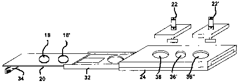
FIG. 1 Is an isometric elevational view of three components : gu0lotine,
spacer, and
frame.
FIGS. tab Side etevational views showing the two basic positions of the
guillotine
and related components in general.
FIGS. 3ab Bottom elevational view showing the two exit holes as well as an air
exit
grille along with the two basic positions of the push pull mechanism.
FIG. 4 Is an isometric elevational view of three components of fig. 3 in their
common
relationship and with the added push out pistons.
FIG. 5 Is an alternate embodiment showing expandability.
3

CA 02448466 2004-07-27
DETAILED DESCRIPTION OF THE PREFERRED EMBODIMENT
FIG. 1 In order to better understand the workings of an accessory for making
patties
from a vacuum filling machine (10), there are three basic elements which are:
A
guillotine (20), a spacer (32) and a frame (24). Both the guillotine (20) and
the spacer
(32) are placed inside of the frame (24). The function of the spacer (32) is
strictly to
allow for a variety of guillotines (20) of different thicknesses. In other
words, the sum
of the thickness of both the guillotine (20) and the spacer (32) should always
be
equal to the space available inside of the frame (24). A flat bar (34),
connected to the
guillotine also connects a push pull means (30) to the guillotine (20).
Passage holes
(38, 38') act as interface between empty shapes (18,18') and exit holes (26,
26') to
allow pass through of foodstuff {12) as seen in
fIG. tab where the foodstuff (12) is received from an exit horn (14) (ghost
lines) of a
vacuum filling machine (not shown) inta an injection head {16). From the
injection
head (16), the foodstuff (12) is forced into the empty shape (18). In fig 2b,
once the
empty shape {18) is filled with the foodstuff (12), the guillotine (20) slides
to the left
{in the figure) until the empty shape (18), which was underneath the injection
head
(16) in fig. 2a is now below a push out piston (22). The push out piston {22)
pushes
the foodstuff (12) while at the same time, another empty shape (18'), now
under the
injection head (16), is being filled with foodstuff (12). Since finro
concurrent steps
occur, that is the making of a patty along with the exiting of a patty, the
accessory
(10) can produce twice as much patties as a traditional one step at a time
machine.
4

CA 02448466 2004-07-27
FIG. 3ab The frame (24) has two exit holes (26, 26') through which the
foodstuff (12)
(not shown) exits. In between these two exit holes (26, 26') is an air exit
grille (28)
which is necessary to allow the foodstuff (12) (not shown) to fill the empty
shapes (18
or 18') and avoid air pockets. A push pull means (30) provides motion to the
guillotine
(20) which, in this view, is mostly hidden by the frame (24}. Although
hydraulic pistons
are currently the favored means of executing the back and fro motion of the
guillotine
(20} for various reasons such as speed, sanitation, low cost and overall
durability, the
use of such pistons as push pull means is shown here strictly as an example
and
should not be construed as limiting since future developments of existing or
yet to
come means may render such a means obsolete.
FIG. 4 Shows the insertion of the guillotine (20) and of the spacer (32) into
the inside
of the frame (24). Dn top of the frame (24) can be seen three entry holes (36,
36'
and 36") where entry holes (36 and 36") are to allow the passage of the push
out
pistons (22, 22') to the empty shapes (18, 18') and entry hole (36') is for
the passage
of the foodstuff (12) (not shown).
FIG. 5 Although previous iAustrations have shown 2 empty shapes (18, 18') and
two
push out pistons (22, 22'), it should be understood that a vacuum filling
machine can
have split exit horns (14) that can feed more than a single injection head
(16) at once
and it is therefore easy to increase the capacity of the accessory for making
patties
from a vacuum filling machine (10} by either placing more than one unit side
by side
or by making larger components such as a larger guillotine (20), spacer (32)
and
s

CA 02448466 2004-07-27
frame (24) so that the result gives the equivalent of 2 or more side by side
accessoy
for making patties from a vacuum filling machine (10).

Representative Drawing
A single figure which represents the drawing illustrating the invention.
Administrative Status

2024-08-01:As part of the Next Generation Patents (NGP) transition, the Canadian Patents Database (CPD) now contains a more detailed Event History, which replicates the Event Log of our new back-office solution.

Please note that "Inactive:" events refers to events no longer in use in our new back-office solution.

For a clearer understanding of the status of the application/patent presented on this page, the site Disclaimer , as well as the definitions for Patent , Event History , Maintenance Fee  and Payment History  should be consulted.

Event History

Description Date
Time Limit for Reversal Expired 2008-11-06
Inactive: Adhoc Request Documented 2008-08-11
Letter Sent 2007-11-06
Grant by Issuance 2005-02-15
Inactive: Cover page published 2005-02-14
Inactive: Final fee received 2004-11-12
Pre-grant 2004-11-12
Notice of Allowance is Issued 2004-10-19
Letter Sent 2004-10-19
Notice of Allowance is Issued 2004-10-19
Inactive: Approved for allowance (AFA) 2004-09-23
Amendment Received - Voluntary Amendment 2004-07-27
Application Published (Open to Public Inspection) 2004-05-08
Inactive: Cover page published 2004-05-07
Inactive: S.30(2) Rules - Examiner requisition 2004-01-27
Inactive: First IPC assigned 2003-12-29
Inactive: IPC assigned 2003-12-29
Inactive: Office letter 2003-12-16
Inactive: Filing certificate - RFE (English) 2003-12-12
Filing Requirements Determined Compliant 2003-12-12
Letter Sent 2003-12-12
Application Received - Regular National 2003-12-12
Request for Examination Requirements Determined Compliant 2003-11-06
All Requirements for Examination Determined Compliant 2003-11-06

Abandonment History

There is no abandonment history.

Fee History

Fee Type Anniversary Year Due Date Paid Date
Request for examination - small 2003-11-06
Application fee - small 2003-11-06
Final fee - small 2004-11-12
MF (patent, 2nd anniv.) - small 2005-11-07 2005-08-29
MF (patent, 3rd anniv.) - small 2006-11-06 2006-08-23
Owners on Record

Note: Records showing the ownership history in alphabetical order.

Current Owners on Record
MARTIN GALLANT
Past Owners on Record
None
Past Owners that do not appear in the "Owners on Record" listing will appear in other documentation within the application.
Documents

To view selected files, please enter reCAPTCHA code :


To view images, click a link in the Document Description column. To download the documents, select one or more checkboxes in the first column and then click the "Download Selected in PDF format (Zip Archive)" or the "Download Selected as Single PDF" button.

List of published and non-published patent-specific documents on the CPD .

If you have any difficulty accessing content, you can call the Client Service Centre at 1-866-997-1936 or send them an e-mail at CIPO Client Service Centre.


Document
Description 
Date
(yyyy-mm-dd) 
Number of pages   Size of Image (KB) 
Description 2003-11-05 6 178
Abstract 2003-11-05 1 21
Claims 2003-11-05 2 48
Drawings 2003-11-05 5 95
Representative drawing 2003-12-29 1 7
Description 2004-07-26 6 147
Claims 2004-07-26 1 27
Acknowledgement of Request for Examination 2003-12-11 1 187
Filing Certificate (English) 2003-12-11 1 170
Commissioner's Notice - Application Found Allowable 2004-10-18 1 160
Notice: Maintenance Fee Reminder 2005-08-08 1 117
Notice: Maintenance Fee Reminder 2006-08-07 1 119
Notice: Maintenance Fee Reminder 2007-08-06 1 121
Maintenance Fee Notice 2007-12-17 1 173
Second Notice: Maintenance Fee Reminder 2008-05-06 1 128
Notice: Maintenance Fee Reminder 2008-08-06 1 122
Correspondence 2003-12-11 1 10
Correspondence 2004-11-11 1 23
Fees 2005-08-28 1 23
Fees 2006-08-22 1 23