Note: Descriptions are shown in the official language in which they were submitted.
CA 02448748 2003-11-07
ROTARY CHEESE GRATER WITH PRESS PLATE SEAL
Background
This application relates to hand-operated food grating devices and, in
particular, to
rotary drum-type graters of the type which are commonly used for grating
cheese and other
similar food products.
A number of different hand-operated rotary drum-type graters have heretofore
been
provided. Typically, in such graters there is a housing defining an open-top
hopper
communicating at its lower end with a cylindrical grating chamber in which is
disposed a
grating drum, rotatable by a crank mechanism attached to the drum at one end
thereof for
grating the contents of the hopper. A handle extends from the housing and is
pivoted at its
distal end to another handle which carries a press plate moveable into and out
of the hopper
between a loading condition, removed from the hopper to permit food items to
be loaded
therein, and a pressing condition, disposable in the hopper for engagement
with the food to
press it against the grating drum. The grating drum is open at one end and
there is substantial
clearance between the press plate and the sidewalls of the hopper to permit
free and
unobstructed movement of the press plate into and out of the hopper.
1 S In use, the two handles are clamped together with one of the user's hands
for pressing
the food items against the grating drum, which is rotated manually by the
user's other hand.
The grated food products fall through grating openings in the grating drum
into the interior of
the drum for discharge from the open end thereof.
Because of the open end of the grating drum and the clearance space between
the press
plate and the hopper sidewall, the interior of the grating drum is exposed to
the atmosphere.
Thus, it is typically necessary, after each use, that the grater be thoroughly
cleaned.
Furthermore, the space between the press plate and the hopper sidewall may
permit food
CA 02448748 2003-11-07
2
items to pass therebetween in operation and not be effectively pressed against
the grating
drum.
Summary
There is disclosed in this application an improved food grater which avoids
disadvantages of prior graters while affording additional structural and
operating advantages.
An improved food grater includes a housing defining a food hopper having a
peripheral wall structure. A grating mechanism is carried by the housing and
communicates
with the hopper for grating food contained therein. A press plate is coupled
to the housing for
movement between an open condition removed from the hopper and a closed
condition
disposed in the hopper for engagement with food disposed therein. Seal
structure is coupled
to the press plate and is disposable in sealing engagement with the peripheral
wall structure
when the press plate is in its closed condition.
The housing may define a grating chamber beneath the hopper in which the
grating
mechanism is disposed. The chamber is closed at one end by handle structure
for operating
the grater and is closeable at an opposite end by a removable cap so that the
handle structure
and cap may cooperate with the seal structure to effectively seal the hopper
and the grating
chamber.
Brief Description of the Drawings
For the purpose of facilitating an understanding of the subject matter sought
to be
protected, there are illustrated in the accompanying drawings embodiments
thereof, from an
inspection of which, when considered in connection with the following
description, the
subject matter sought to be protected, its construction and operation, and
many of its
advantages should be readily understood and appreciated.
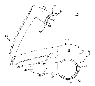
FIG. 1 is a side elevational view of a food grater with a press plate disposed
out of a
food hopper;
CA 02448748 2003-11-07
3
FIG. 2 is a top plan view of the food grater of FIG. 1, with the press plate
disposed in
the hopper and adjacent to a grating mechanism;
FIG. 3 is an enlarged sectional view taken along the line 3-3 in FIG. 2;
FIG. 4 is an enlarged sectional view taken along the line 4-4 in FIG. 2;
FIG. 5 is a bottom plan view of the upper handle and backing plate of the
grater of
FIG. 1;
FIG. 6 is an enlarged, top plan view of the press plate of the grater of FIG.
1;
FIG. 7 is a sectional view taken along the line 7-7 in FIG. 6;
FIG. 8 is an enlarged, top plan view of the seal member of the grater of FIG.
1; and
FIG. 9 is a sectional view taken along the line 9-9 in FIG. 8.
Detailed Description
Referring to FIGS. 1-5, there is illustrated a food grater, generally
designated by the
numeral 10, which includes a housing 11 having a part-cylindrical bottom wall
12 which
defines therein a generally cylindrical grating chamber 13 (FIGS. 3 and 4).
Integral with the
bottom wall 12 and projecting upwardly therefrom is a peripheral wall
structure 14 which
defines an open-top hopper 15 communicating with the grating chamber 13. The
hopper 1 S is
generally rectangular in transverse cross-sectional outline, having a front
wall 16, a rear wall
17 and opposed end walls 18 and 19. Integral with the rear wall 17 and
extending rearwardly
therefrom is an elongated lower handle 20. A shallow notch or recess 21 (FIG.
3) may be
formed in the upper end of the rear wall 17 centrally thereof. The grating
chamber 13 is open
at its opposite ends and the housing 11 defines at one end of the chamber 13 a
cylindrical
bushing surface 22 and forms at the other end thereof a cylindrical bushing
surface 23 which
has formed in the outer end thereof an annular recess 24 (see FIG. 3).
CA 02448748 2003-11-07
4
The grater 10 also includes an elongated upper handle 25 which is coupled at
one end
thereof to the distal end of the lower handle 20 at a pivot 26. Integral with
the upper handle
25 at the forward end thereof and depending therefrom is a plunger arm 27
which has formed
at its distal end a backing plate 28 defining a concave backing surface 29
which, in its as-
manufactured condition, is provided with a plurality of outwardly projecting
lugs 29a (see
FIG. 5).
Disposed in the grating chamber 13 is a grating mechanism, generally
designated by
the numeral 30, which includes a substantially cylindrical grating tube 31
having a plurality of
grating apertures therethrough (not shown), all in a well-known manner. The
grating tube 31
is mounted on a frame 32 and cooperates therewith to define a relatively rigid
grating drum.
The frame 32 includes an end plate 33 substantially annular in shape and
provided with a
laterally outwardly projecting cylindrical hub 34 dimensioned to be coaxially
rotatably
received within the cylindrical bushing surface 22. Projecting laterally
inwardly from the end
plate 33 is a cylindrical, internally threaded well 35. The frame 32 also
includes an annular
end piece 36 connected to the grating tube 31 at its opposite end, the end
piece 36 having a
radially outwardly projecting annular flange 37 and provided in its outer
surface, just
outboard of the flange 37, with a shallow annular groove 38 defining a lip 38a
(FIG. 3). The
flange 37 is dimensioned to be coaxially rotatably received in the annular
recess 24. The end
plate 32 is coupled to the end piece 36 by a plurality of circumferentially
spaced cross braces
39, four of which are illustrated in FIGS. 3 and 4.
The grating mechanism 30 also includes a crank assembly 40, which includes a
crank
arm 41 provided at its distal end with a rotatable knob 42, and provided at
its opposite end
with a generally circular cap plate 43 having an outer diameter greater than
that of the
cylindrical bushing surface 22. Integral with the cap plate 43 centrally
thereof and projecting
CA 02448748 2003-11-07
laterally inwardly therefrom is an externally threaded cylindrical axle 44
adapted to be
threadedly engaged in the well 35 of the end plate 33. Also projecting
laterally inwardly from
the inner surface of the cap plate 43 is a cylindrical stop web 45 which is
positioned to abut
the outer end of the hub 34 to limit the depth of insertion of the axle 44 in
the well 35.
The grater 10 is also provided with a removable cap 47, which may be formed of
a
suitable flexible and resilient material, such as suitable plastic, the cap 47
being provided with
a radially inwardly extending, short, peripheral lip 48 adapted to be snap
fitted past the lip 38a
of the grating mechanism 30 and into the groove 38 for mounting the cap 47 in
place on the
grating mechanism 30, as shown in FIG. 3. It can be seen that, when thus
mounted in place,
the cap 47 cooperates with the crank assembly 40 for closing the opposite ends
of the grating
chamber 13. The cap 47 may be provided with diametrically spaced, laterally
outwardly
projecting tabs 49 (FIGS, l, 2 and 4) to facilitate removal of the cap 47.
Refernng also to FIGS. 6-9, there is mounted on the backing plate 28 a seal
assembly,
generally designated by the numeral 50. The seal assembly 50 includes a seal
member 51
(FIGS. 8 and 9) which is substantially rectangular in plan outline, but is
arcuate in transverse
cross sectional outline, having a concave inner or lower surface 52 and a
convex upper or
outer surface 52a. The outer surface 52a is designed to mateably nest against
the backing
surface 29 of the backing plate 28, the seal member 51 having apertures 54
therethrough for
respectively receiving the lugs 29a of the backing plate 28. The seal member
51 is
dimensioned so that, when disposed against the backing plate 28, it has a
peripheral lip 53
which extends outwardly beyond the periphery of the backing plate 28 around
its entire
perimeter.
The seal assembly 50 also includes a press plate 55 (FIGS. 6 and 7) which is
also
rectangular in plan outline but is arcuate in transverse cross sectional
outline, having a
CA 02448748 2003-11-07
s
concave outer or lower press surface 56 and a convex inner or upper clamp
sufface 57
provided with a plurality of outwardly projecting lugs 58. The press plate 55
is dimensioned
to be slightly larger than the backing plate 28 but substantially smaller than
the seal member
51.
In assembly, the clamp surface 57 of the press plate 55 is fitted against the
inner
surface 52 of the seal member 51, the lugs 58 being respectively received
through the
apertures 54 and abutting the lugs 29a on the backing plate 28 for fixed
attachment thereto, as
by ultrasonic welding. When the press plate 55 and the backing plate 28 are
thus secured
together, they cooperate to clamp the seal member 51 therebetween. While the
backing plate
28 and press plate 55 are dimensioned to be receivable in the hopper 15 with
substantial
clearance from the peripheral wall structure 14, the peripheral lip S3
projects outwardly
beyond the perimeters of the backing plate 28 and the press plate 55, to
completely occupy
this clearance space, as can be seen in FIGS. 1-4.
In operation, the upper handle 25 and the seal assembly 50 are pivotally
moveable
between an open or loading condition, illustrated in FIG. 1, wherein the seal
assembly 50 is
removed from the hopper 15 to permit the insertion therein of food products to
be grated, and
a closed or pressing position, illustrated in FIGS. 2-4, wherein the seal
assembly 50 is
disposable in the hopper 15 for engagement with the food articles therein, for
pressing them
downwardly toward the grating chamber 13 and against the grating tube 31. It
will also be
appreciated that the user grasps the closed-together handles 20 and 25 in ane
hand for
pressing the food articles against the grating mechanism 30 and, with the
other hand, turns the
crank assembly 50 for rotating the grating tube 31 for grating the food
products. The recess
21 in the rear wall 17 provides clearance to permit the seal assembly 50 to be
fully inserted in
the hopper 15 until the press plate 55 engages the grating drum. The grated
food products
CA 02448748 2003-11-07
7
then fall through the grating apertures in the grating tube 31 and into the
interior thereof, all in
a known manner, for discharge from the open end of the grating chamber I3.
Significantly, when the seal assembly SO moves into the hopper 15, the
peripheral lip
53 of the seal member 51 wipes along the inner surface of the peripheral wall
structure 14
around its entire perimeter in sealing engagement therewith (see FIGS. 3 and
4), effectively
preventing the escape of food particles from around the seal assembly 50 and
providing an
essentially air-tight seal of the hopper 15, the flexible and resilient nature
of the seal member
51 accommodating deflection of the peripheral lip 53 to permit this wiping
action. When the
cap 47 is also mounted in place, it cooperates with the crank assembly 40 and
the seal
assembly 50 for effectively sealing both the grating chamber 13 and the hopper
15. Thus, if
desired, food products may be left in the grater 10, specifically in the
hopper 15 and/or in the
chamber 13, and be effectively sealed from exposure to ambient air while the
grater and its
contents may, for example, be stored in a refrigerator. Thus, for example, if
the grater 10 is
being used for grating cheese, the cheese, both grated and ungrated, may be
stored in the
grater 10 until the next use, at which time the cap 47 may be removed to
dispense any grated
cheese from the chamber 13 and continue grating of cheese in the hopper 15.
In a constructional model of the grater 10, the housing 1 I and the upper
handle 25 may
be formed of any suitable metal or plastic materials, as may the grating
mechanism 30. In an
embodiment, the cylindrical grating tube 31 is formed of a suitable metal,
such as stainless
steel, and the seal member 51 is formed of a suitable flexible and resilient
material, such as
silicone, so that the peripheral lip 53 of the seal member SO may readily be
deformed and
deflected to wipe along the inner surfaces of the peripheral wall structure
14. The cap 47 may
also be formed of a flexible and resilient plastic material. All of the
remaining parts of the
grater 10 may be formed of suitable rigid plastic materials, such as ABS. In
particular, the
CA 02448748 2003-11-07
8
backing plate 28 and the press plate 55 may be formed of suitable plastic
materials to
facilitate ultrasonic welding thereof.
The matter set forth in the foregoing description and accompanying drawings is
offered by way of illustration only and not as a limitation. While particular
embodiments
S have been shown and described, it will be apparent to those skilled in the
art that changes and
modifications may be made without departing from the broader aspects of
applicants'
contribution. The actual scope of the protection sought is intended to be
defined in the
following claims when viewed in their proper perspective based on the prior
art.