Note: Descriptions are shown in the official language in which they were submitted.
CA 02448876 2003-11-27
WO 02/102221 PCT/JP02/05743
- 1 -
DESCRIPTION
DEVICE FOR HOLDING CLEANING WIPER AND CLEANING ARTICLE
EMPLOYING HOLDING DEVICE
BACKGROUND OF THE INVENTION
Field of the Invention
The present invention relates to a device for holding
a disposable or reusable cleaning wiper, and also relates to
a cleaning article composed of the holding device and the wiper.
Description of the Related Art
Devices for detachably holding wipers are disclosed in
Japanese Unexamined Patent Publication No. H8-336493
(336493/1996) and Japanese Utility-Model Registration No.
3043196, for example.
In Japanese Unexamined Patent Publication No.HB-336493,
there is disclosed a mop holder having a pair of ring-shaped
support members, which are integrally formed with a handle.
When the paired support members are inserted into a bag-shaped
attachment portion formed in a mop, the ring-shaped support
members are elastically deformed, so that the mop can be held
by the mop holder.
In Japanese Utility-Model Registration No. 3043196, on
the other hand, there is disclosed a cleaning device for holding
a cleaning sheet. This cleaning device has arm portions curved
to extend rearwardly. These arm portions are covered with the
cleaning sheet.
CA 02448876 2003-11-27
WO 02/102221 PCT/JP02/05743
2 -
In these prior arts, elastic deformation of the
ring-shaped support members or the arm portions upon attachment
of the mop or the cleaning sheet makes it possible to firmly
hold the mop or the cleaning sheet.
However, in the mop holder disclosed in Japanese
Unexamined Patent Publication No. H8-336493, when the
ring-shaped support members are attached to the bag-shaped
holding portion of the mop, the outer peripheral edges of the
ring-shaped support members are brought into direct contact
with the inner face of the bag-shaped holding portion to slide
almost entirely along the inner face of the bag-shaped holding
portion of the mop. At this time, due to the elastic repulsive
force of the elastically deformed support members, the sliding
resistance between the outer peripheral edges of the support
members and the bag-shaped holding portion becomes very large.
Therefore, it requires a large force to insert the support
members into the bag-shaped holding portion of the mop till
the end, thereby making it difficult to attach the mop holder
to the mop.
This is also true for the cleaning device disclosed in
Japanese Utility-Model Registration No. 3043196. When the arm
portions are elastically deformed with the cleaning sheet to
be put thereon, the cleaning sheet has to be slid over almost
the entire outer peripheral edges of the arm portions for
attachment. Therefore, the attachment requires a largeforce,
thereby making it difficult to attach the arm portions to the
cleaning sheet.
CA 02448876 2006-O1-18
- 3 -
SUMMARY OF THE INVENTION
The present invention has been worked out in view of
the shortcoming in the prior art set forth above.
There is disclosed a device for holding a cleaning
wiper. The holding device comprises: a synthetic resin body
portion bifurcated to have a pair of support plates to be
inserted into a tube of the wiper; and a handle portion
extending from the body portion to be held by hand. Each
support plate is in an elongated plate form having a width
larger than a thickness. The paired support plates extend
parallel with each other to have inner side edge's facing
each other and outer side edges facing in opposite
directions. Protrusions having convexly curved edges are
integrally formed on the respective outer side edges of the
support plates. The paired support plates are elastically
deformable to permit tip ends thereof to approach each
other.
When the support plates of the holding device are
inserted into the tube of the wiper, the support plates are
deformed, and then, the protrusions whose
CA 02448876 2003-11-27
WO 02/102221 PCT/JP02/05743
- 4 -
edges are convexly curved slide on the inner face of the tube.
Therefore, although the protrusions are brought into contact
with the inner face of the tube by an elastic repulsive force
of the support plates, only the protrusions slide on the inner
face of the tube, thereby reducing sliding resistance and
facilitating attachment of the wiper.
For example, it is preferred that the support plate has
a length of 70 to 170 mm, and a load required to bring the tip
ends of the support plates into contact with each other is 2.4
to 7.4 N. With the length of the support plate and the load
being set within the foregoing ranges, the support plates can
be smoothly inserted into the tube.
It is also preferred that the protrusion comprises an
elastically deformable rib defining a hollow in the protrusion.
With such construction, the sliding resistance between the
protrusions and the inner face of the tube can be reduced by
deformation of the ribs upon insertion of the support plates
into the tube.
Also preferably, the support plate is provided at a root
portion thereof with a thick portion in which the thickness
of the plate is increased. In this case, the tube of the wiper
can be certainly held with the support plates by widening the
end of the tube of the wiper with the thick portions.
It is also preferred that the body portion and the handle
portion are detachably connected through a first coupling on
the side closer to an upper surface of the body portion and
a second coupling on the side closer to a lower surface of the
CA 02448876 2006-O1-18
- 5 -
body portion, and the second coupling uses a coupling
configuration different from that of the first couyling,
thereby eliminating the possibility of connecting the handle
portion to the body portion upside down. With such
construction, the body portion and the handle portion can be
prevented from being assembled upside down by a user.
In accordance with an embodiment of the present
invention there is provided a cleaning article comprising a
holding de vice and a wiper to be attached to the holding
device, the holding device comprising: a synthetic resin
body portion bifurcated to have a pair of support plates to
be inserted into two tubes of the wiper; and a handle
portion extending from the bcdy portion to be held by hand,
each support plate being in an elongated plate form having a
width larger than a thickness, the paired support plates
extending parallel with each other to have inner side edges
facing each other and outer side edges facing in opposite
directions, protrusions having convexly curved edges being
integrally formed on respective outer side edges of the
support plates, the paired support plates being elastically
deformable to permit tip ends thereof to approac.;h each
other, the two tubes of the wiper extending parallel with
each other, each tube having an internal width larger than
the width of the support plate of the holding device so Thai
when the respective support plates are inserted into the
CA 02448876 2006-O1-18
- 5a -
tubes, the protrusions formed on the support plates
slidingly move in the tubes, thereby deforming the support
plates to approach each other.
In this case, it is preferred that narrow internal
width portions, in which the internal width of the tube is
reduced, are provided in intermediate positions of the
respective two tubes of the wiper in a longitudinal
direction thereof so that when the protrusions formed on the
support plates pass the narrow internal width portions, the
paired support plates are deformed to approach each other,
and then, when the support plates are completely inserted
and the protrusions come out of the narrow internal width
portions, the paired support plates move away from each
other, thereby holding the wiper to prevent detachment
thereof from the holding device. With the narrow
CA 02448876 2003-11-27
WO 02/102221 PCT/JP02/05743
- 6 -
internal width portions being thus provided, the wiper can be
certainly held by the holding device.
BRIEF DESCRIPTION OF THE DRAWINGS
The present invention will be understood more fully from
the detailed description given hereinafter and from the
accompanying drawings of the preferred embodiment of the
present invention, which, however, should not be taken to be
limitative to the invention, but are for explanation and
understanding only.
In the drawings:
Fig. 1 is a perspective view showing a cleaning article
comprising a holding device and a wiper according to one
embodiment of the present invention;
Fig. 2 is an exploded perspective view showing the holding
device alone;
Figs . 3A, 3B and 3C are a top plan view, a sectional view
and a bottom plan view of a body portion of the holding device;
Figs . 4A, 4B and 4C are a top plan view, a side view and
a bottom plan view of a handle portion of the holding device;
Fig. 5 is a sectional view showing a connecting portion
of the handle portion, taken along line V - V of Fig. 4A;
Fig. 6 illustrates a condition where the wiper is in the
middle of attachment to the holding device; and
Fig. 7A illustrates a condition where the wiper is
attached to the holding device, and Fig. 7B is a sectional view
of Fig. 7A.
CA 02448876 2003-11-27
WO 02/102221 PCT/JP02/05743
DESCRIPTION OF THE PREFERRED EMBODIMENT
The present invention will be discussed hereinafter in
detail in terms of the preferred embodiment according to the
present invention with reference to the accompanying drawings.
In the following description, numerous specific details are
set forth in order to provide a thorough understanding of the
present invention. It will be obvious, however, to those
skilled in the art that the present invention may be practiced
without thesespecific details. In other instance, well-known
structures are not shown in detail in order to avoid unnecessary
obscurity of the present invention.
Fig. 1 is a perspective view showing a cleaning article
comprising a holding device and a wiper according to one
embodiment of the present invention; Fig. 2 is an exploded
perspective view showing the holding device alone; Figs. 3A,
3B and 3C are a top plan view, a sectional view and a bottom
plan view of a body portion of the holding device; Figs. 4A,
4B and 4C are a top plan view, a side view and a bottom plan
view of a handle portion of the holding device; Fig. 5 is a
sectional view showing a connecting portion of the handle
portion, taken along line V - V of Fig. 4A; Fig. 6 illustrates
a condition where the wiper is in the middle of attachment to
the holding device; and Fig. 7A illustrates a condition where
the wiper is attached to the holding device, and Fig. 7B is
a sectional view of Fig. 7A.
As shown in Fig. l, the cleaning article is composed of
CA 02448876 2003-11-27
WO 02/102221 ~ PCT/JP02/05743
_ $ _
a disposable wiper 1 and a holding device 2 to which the wiper
1 is to be attached. As shown in Fig. 2, the holding device
2 can be disassembled into a body portion 10 and a handle portion
30.
The individual body portion 10 and handle portion 30 are
injection molded of polyolefin resin, such as polypropylene
(PP).
As shown in Fig. 3A, the body portion 10 has a connecting
portion 11 of a length LO at its root portion, and bifurcated,
forwardly of the connecting portion 11, to have a pair of support
plates 12 and 12 of a length L1. Outer side edges 12a and 12a
of the support plates 12 and 12 extend generally linearly and
parallel with each other.
The individual support plates 12 and 12 have a constant
width W1 over a predetermined length range, forwardly of the
connecting portion 11, so that inner side edges 12b and 12b
of the support plates 12 and 12 extend parallel with each other
over the range. Therefore, the spacing W2 between the inner
side edges 12b and 12b facing each other is constant. Over a
range of length L2 at the tips of the support plates 12 and
12, the inner side edges of the support plates 12 and 12 are
tapered (hereinafter, referred to as tapered side edges 12c
and 12c) . The tapered side edges 12c and 12c are formed such
that the spacing W3 therebetween~gradually increases as
approaching the tip ends of the support plates 12 and 12.
Therefore, over the range of the length L2, the width of the
individual support plates 12 gradually decreases as
CA 02448876 2003-11-27
WO 02/102221 PCT/JP02/05743
- 9 -
approaching the tip end thereof.
As shown in Fig. 3B, the support plates 12 and 12 have
a generally constant thickness T1 over a predetermined length
range . Here, the support plates 12 and 12 have longitudinally
elongated recesses 12d on their lower surfaces, as shown in
Fig. 3C, but the thickness T1 refers to a thickness of the
portions surrounding the recesses 12d of the support plates
12 and 12. The support plates 12 and 22 are formed at their
root portions with thick portions 13 and 13, which have a
thickness T2 larger than the thickness T1. The front ends 14
and 14 of the thick portions 13 and 13 are curved to gradually
increase in thickness rearwardly. In the top plan view of Fig.
3A, the front ends 14 and 14 are arcuate or convexly curved.
On the respective outer side edges 12a and 12a of the
support plates 12 and 12, there are formed protrusions 15
projecting outwardly. The protrusion 15 has a length L3. The
protrusions 15 are disposed in two positions on the respective
outer side edges 12a and 12a of the support plates 12 and 12.
The peak to peak distance W4 between the protrusion 15 disposed
on one support plate 12 and the protrusion 15 disposed on the
other support plate 12 is larger than the distance W5 between
the outer side edges 12a and 12a.
The edge of the protrusion 15 is convexly curved, and
a hollow 15a is formed in the protrusion 15. The portion
defining the hollow 15a is referred to as rib 15b. The rib 15b
is elastically deformable in such a direction that the hollow
15a can decrease in volume.
CA 02448876 2003-11-27
WO 02/102221 PCT/JP02/05743
- IO -
Between the paired support plates 12 and 12, a holding
plate 16 is integrally formed to extend from the connecting
portion 11. As shown in Fig. 3B, the holding plate 16 is
downwardly convexly curved, and integrally formed at its lower
surface with an engaging protrusion 16a which will engage the
wiper I when the body portion 10 moves rightward as seen in
the drawing.
The connecting portion 11 of the body portion 10 has a
first mating recess 21 on the side closer to the upper surface
and a second mating recess 22 on the side closer to the lower
surface. As seen from Figs. 3A and 3C, the first and second
mating recesses 22 and 22 are different in outline: the first
mating recess 21 being of a generally round outline; the second
mating recess 22 being of a generally rectangular outline.
' Between the first and second mating recesses 21 and 22,
a mating plate 23 is integrally formed. The mating plate 23
is formed with a recess 24 . As shown in Figs . 3B and 3C, moreover,
a pair of retaining projections 25 and 25 are formed to project
from the lower surface of the mating plate 23. These retaining
projections 25 and 25 have edges 25a and 25a directed toward
the support plates 12 and 12.
As shown in Figs. 4A, 4B and 4C, for the handle portion
30, a connecting portion 31 and a handle 32 are integrally
formed.
The connecting portion 31 has a first mating protrusion
33 on the side closer to the upper surface and a second mating
protrusion 34 on the side closer to the lower surface. Between
CA 02448876 2003-11-27
WO 02/102221 PCT/JP02/05743
- 11 -
the first and second mating protrusions 33 and 34, there is
left a clearance 35, except for a mating protrusion 36
integrally formed therebetween. Asshown in Fig.4C,moreover,
the second mating protrusion 34 is formed with two retaining
holes 37 and 37.
The outline of the first mating recess 21 of the body
portion 10 and the outline of the first mating protrusion 33
of the handle portion 30 are identical to thereby form a first
coupling. The outline of the second mating recess 22 of the
body portion 10 and the outline of the second mating protrusion
34 of the handle portion 30 are identical to thereby form a
second coupling. Thus, the second coupling uses a coupling
configuration different from that of the first coupling
For connecting the body portion 10 to the handle portion
30, the first mating protrusion 33 of the handle portion 30
is fitted in the first mating recess 21 of the body portion
10; and the second mating protrusion 34 of the handle portion
30 is fitted in the second mating recess 22 of the body portion
10. At this time, the mating plate 23 of the body portion 10
is inserted into the clearance 35 of the handle portion 30,
and the mating protrusion 36 of the handle portion 30 is mated
with the recess 24 of body portion 10. In addition, the
retaining projections 25 provided on the lower surface of the
mating plate 23 of the body portion 10 engage the retaining
holes 37 and 37 formed in the second mating protrusion 34 of
the handle portion 30. Thus, the body portion 10 and the handle
portion 30 are firmly engaged.
CA 02448876 2003-11-27
WO 02/102221 PCT/JP02/05743
- 12 -
The body portion 10 and the handle portion 30 thus
connected can be forcibly separated by disengaging the coupling
between the retaining projections 25, 25 and the retaining holes
37, 37. ,
It should be noted that even if a user tries to connect
the body portion 10 and the handle portion 30 upside down, the
second mating protrusion 34 of the handle portion 30 can not
enter the first mating recess 21 of the body portion 10, thereby
preventing the body portion 10 and the handle portion 30 from
being connected upside down.
In the body portion 10, the support plates 12 and 12 are
in the form of thin elongated plate, and elastically deformable
in directions a so that the tapered side edges 12c and 12c may
come into contact with each other . In order to make the support
plates 12 and 12 deformable in the directions cr to the extent
that permits the tapered side edges 12c and 12c to come into
contact with each other, it is preferred that the width W1 of
the respective support plates 12 and 12 is in a range of 5 to
mm and the length h1 is in a range of 70 to 170 mm. It is
20 also preferred that a load required to deform the support plates
12 and 12 in the directions a and bring the tapered side edges
12c and 12c into contact with each other, is from 2.4 to 7.4
N. Below the foregoing limit, the wiper 1 can not be firmly
held with the support plates 12 and 12. In excess of the
foregoing limit, it requires too much force to deform the
support plates 12 and 12 in the directions cx for attachment
CA 02448876 2003-11-27
WO 02/102221 PCT/JP02/05743
- 13 -
of the wiper 1, making it difficult to attach the wiper 1.
Here, the load can be measured using a measuring
instrument such that the outer side edge 12a of one support
plate 12 is supported by the measuring instrument, the outer
side edge 12a of the other support plate 12 is pushed, and the
scale of the measuring instrument is read when the tapered side
edges 12c and 12c come into contact with each other.
The support plates 12 and 12 are also deformable to bend
upwardly in the drawing of Fig. 3B. To this end, the thicknesses
T1 and T2 are set smaller than the width W1. For example, it
is preferred that the thickness T1 is of the order of 1 to 4
mm and the thickness T2 is of the order of T1 + 1 to 5 mm.
On the other hand, when a value measured using a measuring
instrument such that the lower surfaces of the support plates
12 and 12 are supported on the measuring instrument over a range
of one-half of the length Z1 from the tip ends of the support
plates 12 and 12 and then the rear end of the connecting portion
11 is lifted up by 25 mm from the surface of the measuring
instrument, is taken as bending strength, the bending
resistance preferably ranges between 3 and 15 N. Below the
foregoing limit, the support plates 12 and 12 are too soft to
certainly press the wiper 1 against an object to be cleaned
by holding the handle 32 . This results in decreasing the wiping
effect due to the wiper 1. In excess of the foregoing limit,
the support plates 12 and 12 are excessively hard and a reaction
force of pressing against the object to be cleaned directly
acts on the hand holding the handle 32, so that the wiping
CA 02448876 2003-11-27
WO 02/102221 PCT/JP02/05743
- 14 -
operation becomes difficult.
On the other hand, the length 1,3 of the protrusion 15
is about 8 to 25 mm. In addition, the protrusion 15 protrudes
from the outer side edge 12a of the support plate 12 by about
3 to 10 mm. Moreover, the rib 15b of the protrusion 15 has a
thickness of about 0.5 to 2 mm.
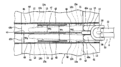
Next, the wiper 1 shown in Figs. 1, 6 and 7 comprises
a body portion 41, which is formed from a nonwoven fabric, a
laminate of nonwoven fabrics, a foamed resin material, or any
other suitable materials . On the upper face of the body portion
41, there is disposed a holding sheet 42.
The body portion 41 and the holding sheet 42 are joined
to each other at a center fusion-bond line 43 extending
longitudinally of the wiper 1 and a pair of side fusion-bond
lines 44 and 44 which are spaced apart from the center
fusion-bond line 43 by Wa sidewardly. Between the center
fusion-bond line 43 and the respective side fusion-bond lines
44, 44, there are formed a pair of elongated tubes (holding
spaces) 45 and 45.
The body portion 4I and the holding sheet 42 are further
joined to each other at narrowing fusion-bond lines 46 and 46,
which are located in intermediate positions of the tubes 45
and 45 in the longitudinal (lengthwise) direction thereof and
between the side fusion-bond lines 44 and 44. In the positions
where the narrowing fus ion-bond lines 4 6 and 4 6 are provided,
therefore, there are formed narrow internal width portions 47
and 47 having an internal width Wb between the center
CA 02448876 2003-11-27
WO 02/102221 PCT/JP02/05743
- 15 -
fusion-bond line 43 and the respective narrowing fusion-bond
lines 46 and 46. In the front and rear portions outside of the
narrow internal width portions 47 and 47, on the other hand,
the tubes 45 and 45 provide wide internal width portions 48
and 4 8 having the internal width Wa . The tubes 4 5 and 4 5 have
openings 45a and 45b at their front and rear ends.
Both the internal width Wb of the narrow internal width
portions 47 and the internal width Wa of the wide internal width
portions 48 are larger than the width W1 of the support plates
12 and 12 of the holding device 2. In addition, the distance
Wd between the side fusion-bond lines 44 and 44 is larger than
the distance W5 between the outer side edges 12a and 12a shown
in Fig. 3A and substantially equal to or slightly smaller than
the peak to peak distance W4 between the protrusions 15 and
15. Moreover, the distance We between the narrowing
fusion-bond lines 46 and 46 is equal to or slightly larger than
the distance W5 between the outer side edges 12a and 12a shown
in Fig. 3A and sufficiently smaller than the peak ~to peak
distance W4 between the protrusions 15 and 15.
In the embodiment shown in Figs. 1 and 6, the narrowing
fusion-bond lines 46 and 46 are provided between and separately
from the side fusion-bond lines 44 and 44: However, it is also
possible to integrate the narrowing fusion-bond lines 46 and
46 with the side fusion-bond lines 44 and 44. That is, the line
width of the side fusion-bond lines 44 and 44 may be increased
toward the center fusion-bond line 43 in the narrow internal
width portions 47 to provide the internal width Wb, while
CA 02448876 2003-11-27
WO 02/102221 PCT/JP02/05743
- 16 -
maintaining the internal width Wa between the center
fusion-bond line 43 and the respective side fusion-bond lines
44 in the wide internal width portions 48.
Fig. 6 illustrates a condition where the wiper 1 is in
the middle of attachment to the holding device 2.
The tip ends of the support plates 12 and 12 of the holding
device 2 are inserted into the tubes 45 and 45 of the wiper
1 through the openings 45a ( insertion through the openings 45b
is also possible) . As the protrusions 15 and 15 provided close
to the tip ends of the support plates 12 and 12 enter the wide
internal width portions 48 and 48 of the tubes 45 and 45, the
support plates 12 and 12 are slightly deformed in the directions
er , and the edges of the protrusions 15 and 15 slide along the
inner sides of the side fusion-bond lines 44 and 44.
When the edges of the protrusions 15 and 15 are brought
into contact with the ends of the narrowing fusion-bond lines
46 and 46, then, the force to insert the support plates 12 and
12 is converted into a force to deform the support plates 12
and 12 in the directions ex due to the convexly curved shape
of the protrusions 15 and 15. Therefore, the support plates
12 and 12 are largely deformed in the directions a to bring
the edges of the protrusions 15 and 15 into contact with the
inner sides of the narrowing fusion-bond lines 46 and 46. As
the support plates 12 and 12 are inserted farther, then, the
edges of the protrusions 15 and 15 slide along the inner sides
of the narrowing fusion-bond lines 46 and 46 due to the elastic
recovery force of the support plates 12 and 12 tending to move
CA 02448876 2003-11-27
WO 02/102221 PCT/JP02/05743
- 17 -
away from each other.
Thus, the edges of the protrusions 15 and 15 slide along
the inner sides of the narrowing fusion-bond lines 46 and 46
while being pressed against them due to the elastic recovery
force of the support plates 12 and 12 . However, since the length
L3 of the protrusions 15 and 15 is not large and the edges of
the protrusions 15 and 15 are convexly curved, the sliding area
between the edges o f the protrus ions 15 , 15 and the inner s ides
of the narrowing fusion-bond lines 46, 46 is always small. In
addition, since the support plates 12 and 12 are of the elongated
plate form, the elastic repulsive force when the support plates
12 and 12 are deformed in the directions a is not very large.
Accordingly, the sliding load between the edges of the
protrus ions 15 , 15 and the narrowing fus ion-bond lines 4 6 , 4 6
is not heavy, so that it requires only a small force to insert
the holding device 2 into the wiper 1 farther than the state
shown in Fig. 6 to the end.
Here, a.t may possibly happen that although the support
plates 12 and 12 are deformed to the maximum limit in the
directions a for insertion into the narrow internal width
portions 47 and 47, the peak to peak distance between the
protrusions 15 and 15 is. still slightly larger than the distance
We between the narrowing fusion-bond lines 46 and 46. In this
case, the ribs 15b and 15b of the protrusions 15 and 15 are
deformed in directions to decrease the areas of the hollows
15a and 15a, thereby enabling the protrusions 15 and 15 to pass
through the narrow internal width portions 47 and 47.
CA 02448876 2003-11-27
WO 02/102221 PCT/JP02/05743
- 18 -
When the protrusions 15 and 15 provided close to the tip
ends of the support plates 12 and 12 go beyond the narrowing
fusion-bond lines 46 and 46 to complete the insertion of the
holding device 2 into the wiper 1, as shown in Fig. 7A, the
support plates 12 and 12 move away from each other due to the
elastic recovery force of the support plates 12 and 12, so that
the respective narrowing fusion-bond lines 46 and 46 are
sandwiched between the two protrusions 15 and l5~of the
respective support plates 12 and 12, thereby holding the wiper
1 so as not to detach from the holding device 2.
At this time, at the openings 45a and 45a of the tubes
45 and 45, the holding sheet 42 is placed below the holding
plate 16 and firmly retained by the engaging protrusion 16a
provided on the lower surface of the holding plate 16, as shown
in Fig. 7B. In addition, the thick portions 13 and 13 of the
body portion 10 of the holding device 2 enter the openings 45a
and 45a of the tubes 45 and 45 to increase the pressure to the
holding plate 16 and the holding sheet 42, thereby increasing
the clamping force of the holding plate 16 against the holding
sheet 42 . Thus, the wiper 1 can be certainly held by the holding
device 2, preventing undesirable separation of the wiper 1 from
the holding device 2 during wiping operation.
On the other hand, when the wiper 1 is detached from the
holding device 2, the protrusions 15 and 15 provided close to
the tip ends of the support plates 12 and 12 of the holding
device 2 slide into the space between the narrowing fusion-bond
lines 46 and 46, and the support plates 12 and 12 are deformed
CA 02448876 2003-11-27
WO 02/102221 PCT/JP02/05743
- 19 -
in the directions a, as shown in Fig. 6. At this time, too,
since the edges of the protrusions 15 and 15 are convexly curved,
the protrusions 15 and 15 can enter the space between the
narrowing fusion-bond lines 46 and 46 smoothly. Therefore, the
wiper 1 can be easily detached from the holding device 2.
As another embodiment of the present invention, it is
also possible that the holding device 2 has a single support
plate, two protrusions 15 and 15, which are shown in the
embodiment of Fig. 1 and so on, are formed on each side edge
of the single support plate, and the protrusions 15 are
constructed to have a hollow 15a and a rib 15b. In this case,
the wiper 1 is provided with a ingle tube. When the support
plate is inserted into the tube, the ribs are elastically
deformed so that the support plate may pass through the narrow
internal width portion. When the support plate is completely
inserted into the tube, on the other hand, the ribs are
elastically recovered in the wide internal width portion to
hold the wiper.
According to the present invention, as has been described
above, the holding device can be smoothly attached to the wiper
and the wiper can be certainly held by the holding device.
Although the present invention has been illustrated and
described with respect to exemplary embodiment thereof, it
should be understood by those skilled in the art that the
foregoing and various other changes, omission and additions
may be made therein and thereto, without departing from the
spirit and scope of the present invention. Therefore, the
CA 02448876 2003-11-27
WO 02/102221 PCT/JP02/05743
- 20 -
present invention should not be understood as limited to the
specific embodiment set out above but to include all possible
embodiments which can be embodied within a scope encompassed
and equivalent thereof with respect to the feature set out in
the appended claims.