Note: Descriptions are shown in the official language in which they were submitted.
CA 02449205 2003-12-01
1
Method and device for low-emission, non-catalytic combustion
of a liquid fuel
The invention relates to a method and a device for low-
emission, non-catalytic combustion of a liquid fuel.
From the state of art a burner is known from DE 43 22 109 A
with which an ignitable gas/air mixture is fed to a chamber
located in front of a pore body. The porosity of the pore
body is formed so that a backfire of a flame in the chamber
is not possible. However, it cannot be excluded that an igni-
tion may take place in the chamber for another reason and
thus destroy burner.
The subsequently published DE 100 42 479 Al discloses a de-
vice and a method for the catalytic oxidizing of fuels. With
this, fuel and air are fed to a mixing area which is followed
by a catalytic converter. Due to damage to the catalytic con-
verter, for example, an undesired ignition may occur in the
mixing area.
DE 195 44 417 Al describes a catalytic burner for the combus-
tion of fuel gas, in particular hydrogen. With this, the fuel
gas and the air are fed separately into a porous catalytic
converter element. The mixture and the combustion take place
simultaneously in the catalytic converter element. Sometimes
a homogenous mixture of fuel gas and air is not achieved. The
combustion is not always complete.
DE 196 46 957 Al describes a further burner which is suitable
for the combustion of liquid fuel. With this, a mixture con-
sisting of atomized liquid fuel and air is fed into a pore
body. The pore body is formed in its porosity so that combus-
tion of the mixture can take place therein. The mixture is
moved over a flame arrester to a further pore body which is
422269-Snvent-asz (engl _ )-i
1
CA 02449205 2009-07-02
29824-34
2
positioned down current with a Peclet number of > 65 and is
burned there. The known burner has a relatively low perform-
ance dynamic, i.e., it can only be modulated within a narrow
per=formance range. During operation, high temperatures occur
on the jet outlet of the vaporization jet. Deposits are gen-
erated there which hinder uniform atomization-of the liquid
fuel. This then detracts from as low-emission a combustion as
possible.
The object of the invention is to eliminate the disadvantages
based on the state of art. In particular, it is to be speci-
fied a method and a device which permit as residue-free com-
bustion as possible within a wide performance range. In par-
ticular, the goal of the invention is to specify a burner
with high modulation capacity which permits particularly low-
emission combustion in every performance range.
This object is solved by the features of claims 1 and 12.
Useful embodiments of the invention result from the features
of claims 2 to 11 and 13 to 23.
In accordance with an initial solution provided by the inven-
tion, a method for low-emission, non-catalytic combustion of
a liquid fuel is provided consisting of the following steps:
separately introducing the liquid fuel in a non-ignitable status into a mixing
zone,
vaporizing the liquid fuel in the mixing zone,
separately introducing a gaseous oxidizing agent into the mixing zone,
mixing the fuel and the gaseous oxidizing agent in the mixing zone so that
an ignitable mixture is created,
CA 02449205 2009-07-02
29824-34
3
wherein the mixing zone is formed so that combustion is
not possible even when the ignition temperature of the
mixture is reached within the mixing zone, and
combusting the mixture in a combustion zone located down current from the
mixing zone.
The vaporization of the liquid fuel in the mixing zone per-
mits the construction of a particularly compact burner. With
this, it is ensured that the fuel produced by the vaporiza-
tion does not come in contact with the oxidizing gas until
the mixing zone and an ignitable mixture can thus not be
formed until then.
In accordance with a second solution provided by the inven-
tion, a method for low-emission, non-catalytic combustion of
a liquid fuel is provided consisting of the following steps:
vaporizing the liquid fuel in a vaporizer,
separately introducing the vaporized fuel in a non-ignitable state into a
mixing zone located down current from the vaporizer,
separately introducing a gaseous oxidizing agent into the mixing zone,
mixing the fuel and the gaseous oxidizing agent in the mixing zone so that
an ignitable mixture is created, wherein the mixing zone is formed so that
combustion is not possible even when the ignition temperature of the mixture
is
reached within the mixing zone, and
combusting the mixture in a combustion zone down current from the mixing
zone.
CA 02449205 2003-12-01
4
The suggested methods permit a low-residue combustion over a
wide performance range. The separate introduction of the fuel
and the gaseous oxidizing agent into a mixing zone permits
separate control and Tegulation of the mass flow of both the
gas and the gaseous oxidizing agent. This can-be used to set
a mixture in every desired performance range which allows
low-emission Combustion. The term fuel is primarily used to
mean liquid fuel such as light heating oil and similar but
also vaporized liquid fuels such as alcohol, benzine or heat-
ing oil fumes. Further, the term "fuel" is also used to mean
mixtures of flammable and non-flammable gases or of non-
flammable gases and flammable fumes.
Since the mixing zone is formed so that a combustxon is not
possible even when the ignition temperature of the mixture is
reached within the mixing zone, the method is particularly
safe. Also when one of the combustion zones, for example of
fulfilling pore bodies, is damaged, the mixing zone reliably
prevents a flame backfire in a line feeding in the fuel. The
mixing zone is clearly defined spatially. This means that a
homogenous and complete mixture of the mixture can be
achieved. - Hoth solutions provided by the invention have in
common that the mixture is created first in the mixing zone
and then the mixture is burned in the combustion zone which
is separated spatially from the mixing zone. Mixing and com-
bustion do not take place simultaneously in the same zone.
It is possible that the mixing zone has a P6clet number of
less than 65 +/- 25, preferably 65. Due to the definition of
the Peclet number and the criteria for the se].ection of a
suitable Peclet number, reference is made to DE 43 22 109 Al
whose disclosed contents are herewith included. The suggested
method is particularly safe. Due to the separate and immedi-
ate introduction of the fuel and the gaseous oxidizing agent
422269-Tnvent-ari(eng1.)-1
1 ; .
CA 02449205 2003-12-01
S
into the mixing zone, an ignition of same is reliably pre-
vented until complete formation of the mixture.
The mixing zone can be generated from a perforated plate, a
first porous element or also a narrow alit. It has been shown
to be advantageous that the mixture is fed to-a second porous
element which creates the combustion zone and is burned under
formation of a flame in its pore volume. Such a combustion is
particularly homogenous and low in emission. The perforated
plate and/or the first and/or the second
Porous element can be made of a ceramic. However, the first
and/or second porous element can also be made of an open-pore
metal foam, metal braiding or a pile of ceramic bodies, pref-
erably balls.
The first and the second porous elements can be located lying
directly next to each other. In this case, a direct heat con-
ductance from the second porous element to the first porous
element is possible. The thus caused heat of the first porous
element contributes further to the generation of a particu-
larly homogenous mixture.
During vaporization, a non-oxidizing gas can be added. This
can reduce the ignitability of the vaporized fuel.
zt is possible that the mass flow of the fuel led to the mix-
ing zone and/or the mass flow of the gaseous oxidizing agent
are controlled. Each of the two mass flows can thereby be
controlled separately or also regulated in dependence on a
specified capacity or a specified amount of emission. Such a
regulation can be automated using microprocessors following a
specified program.
422269-Tnvent-an(eng1.)-1
^ ti
CA 02449205 2009-07-02
29824-34
6
Further, it has been shown to be useful that the fuel and/or
the gaseous oxidizing agent is/are preheated. For preheating,
the exhaust generated during combustion can be added to the
vaporized fuel and/or the gaseous oxidizing agent. The pollu-
tion emission can be further reduced with this. Also this can
be used to increase the performance of a burner operating
with the suggested method.
Further, according to the invention, a device is provided for
low-emission, non-catalytic combustion of a liquid fuel with
a mixing zone and a combustion zone located down current from
the mixing zone, wherein there are connected to the mixing
zone a means of separate introduction of the liquid or vapor-
ized fuel in a non-ignitable state and a means of separate
introduction of a gaseous oxidizinq acrent,_and wherein the
mixing zone is formed having a Peclet number of less than 65 so that
combustion
is not possible even when the ignition temperature of the mixture is reached
within the mixing zone. - The suggested device has extremely
high performance dynamics. For instance, the performance can
be varied in the range from 1 kW to 20 kW.
Due to the optimized embodiments of the device, reference is
made to the description of the preceding features which can
be correspondingly applied equally.
The invention will how be described in more detail using ex-
amples based on the drawing. It is shown:
Fig. 1 Schematically the function of a first device,
Fig. 2 schematically the function of a second device,
Fig. 3 schematically the function of a third device,
Fig. 4 schematically the function of a fourth device,
CA 02449205 2009-07-02
29824-34
7
Fig. 5 schematically the function of a fifth device,
Fig. 6 schematically the function of a sixth device.
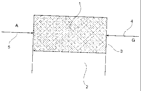
Fig. 1 schematically shows the function of a first device. A mixer 1 is formed
here,
for example, from a porous ceramic with a Peclet number of less than 65. The
mixer 1 is opened towards a combustion zone 2. Otherwise the mixer 1 is
surrounded on all sides by a gas-proofing housing 3. The housing is located
immediately next to the surface of the porous ceramic. In the housing,
connections are provided for a line 4 for feeding in fuel and a line 5 for
feeding in a
gaseous oxidizing agent such as air. A blower can be provided in the line for
feedirig in a gaseous oxidizing agent A.
The fuel can be expanded in the mixer directly from the liquid state. It is
also
possible to feed to the mixer 1 a mixture formed from the fuel and a non-
ignitable
gas G. An ignitable mixture is generated in the mixer 1 from the fuel and the
gaseous oxidizing agent. Combustion of the ignitable mixture in the mixer 1 is
not
possible due to the selected porosity, i.e., a Peclet number of less than 65.
The
mixture exits the mixer 1 and is burned in the combustion zone provided down
current.
The rriass flow of both the gaseous oxidizing agent A and the fuel can be
regulated separately. The performance of the burner can thus be modulated in a
wide range.
Further, low-emission combustion can be achieved in any selected performance
range.
Fig. 2 shows a burner in accordance with Fig. 1. The fuel is made here with a
device 6 for vaporizing heating oil. It is formed from a non-ignitable oil
vapor. The
air number A or oil vapor is selected so that ignition capability does not
exist.
CA 02449205 2009-07-02
29824-34
8
The heating oil 0 used here can be mixed with preheated heating oil OP to
accelerate vaporization. However, the used heating oil can also be preheated
by
electrical power, for example, or by the heat emitted by the exhaust fumes
generated during combustion. In the same way, the used gaseous oxidizing
agent A such as air can be preheated with electrically preheated air or air
warmed
by exhaust-fume heat. It is also possible to mix both the used liquid fuel and
the
gaseous oxidizing agent A with exhaust fumes and feed this to the mixer 1.
Fig. 3 shows a third version of a device provided by the invention. Here, a
device
for vaporization of liquid fuel is directly coupled to the mixer 1. Liquid
fuel such as
domestic heating oil 0 is fed to a vaporization device 6 made from a further
porous element. The further porous element is heated by the heat of
combustion.
The liquid fuel is vaporized in the further porous element. The gas created by
this
enters the mixer which is positioned down current. Further, the gaseous
oxidizing
agent which is fed separately through a further device 7 for vaporization
enters the
mixer 1. The mixture is formed first in the mixer 1.
Fig. 4 shows a fourth version of a device provided by the invention. The
device is
similar to the device shown in Fig. 2. Exhaust is returned here. The returned
exhaust is used for the vaporization of the liquid fuel as well as for the
mixture of
the thereby created vapor and for the preheating and mixture of the gaseous
oxidizing agent.
Fig. 5 shows a fifth version of a device provided by the invention. With this,
liquid
fuel such as heating oil 0 is vaporized in a further porous element. The thus
created vapor enters a narrow slit and is mixed there with the fed in gaseous
oxidizing agent or air. The width of the slit is selected so that an ignition
cannot
take place within the slit. The created premixture then enters the mixer which
in
turn can be formed from a porous element which has a Peclet number of less
than
65. Down current of the mixer is provided in turn a combustion zone in which
the
homogenous mixture exiting the mixer is burned.
CA 02449205 2009-07-02
29824-34
9
Fig. 6 shows a sixth device provided by the invention. With this, gaseous
oxidizing agent such as air, and non-ignitable vapor is fed separately to a
perfor=ated plate 8. The jets of the feeder lines 4,5 for fuel and gaseous
oxidizing
agent are arranged so that an ignition cannot take place up current from the
mixing zone 1. With respect to its perforation diameter, the mixing zone 1
itself is
in turn formed so that an ignition of the created mixture also cannot take
place
therein. The mixture is burned in a combustion zone 2 located after the mixing
zone 1.