Note: Descriptions are shown in the official language in which they were submitted.
CA 02449276 2003-11-13
WALKBOARD LEDGER FOR SCAFFOLDING
BACKGROUND OF THE INVENTION
1. Field of the Invention
The present invention relates generally to scaffolding for supporting a worker
elevated above the ground. More specifically, the present invention concerns a
walkboard
ledger for scaffolding that better prevents undesired shifting of a walkboard
supported on the
ledger and is easier to incorporate into the scaffolding than the prior art
ledgers. The
inventive ledger provides a positive nonslip removable coupling of the
walkboard and the
ledger that prevents unsafe and inadvertent shifting of the walkboard along
the ledger when
pressure is applied to the walkboard by the worker.
2. Discussion of Prior Art
It is known in the art to utilize scaffolding to provide an elevated walkboard
to elevate a worker above a floor or ground surface to complete a task (e.g.,
painting, drywall
finishing, etc.). The walkboard typically consists of one or more planks
having a relatively
flat supporting surface. The planks can be formed of a variety of materials
including wood
(e.g., 2'X10' lumber, etc.) or metal (e.g., aluminum, etc.). The scaffolding
utilized to provide
the elevated walkboard is often adjustable so that the elevation of the
walkboard can be
quickly and easily modified. For example, it is known in the art to provide
the scaffolding
with a plurality of ledgers positioned at various elevations, with each ledger
configured to
support one or more walkboard at the corresponding elevation. The ledgers are
typically
round tubes that also function as steps or rungs for use by the worker. The
walkboard is
typically not fastened to the ledgers to enable the walkboard to be readily
movable between
ledgers in order to adjust the elevation of the walkboard. For example, when a
wood plank
is used, the plank is typically simply laid across the ledger. Prior art metal
planks sometimes
include sidewalk with cut outs configured to fit around the ledger. In
addition, the ledger is
commonly wider than the width of a single walkboard to enable multiple
walkboards to be
placed on a single ledger and to enable a single walkboard to be adjustably
positioned along
a ledger. In some applications, it is desirable to support multiple walkboards
at differing
elevations (e.g., in a step-like arrangement) on a single scaffolding system.
In these
instances, the walkboards are typically offset to facilitate the worker moving
from walkboard
1
CA 02449276 2003-11-13
to walkboard. It is further known in the art to utilize a system of modular
scaffolding to
support a series of walkboards for elevating the worker or workers along a
greater work area.
When utilizing a series of walkboards spanning between two or more modules, it
is
sometimes desirable to support successive walkboards at a different elevation
(e.g., when
using a walkboard to span between adjacent scaffolding units, etc.). In all of
these
applications, serious safety concerns arise when the walkboard undesirably
shifts along the
ledger under the weight of the worker. Therefore, it is desirable to prevent
the walkboard
from shifting along the ledger yet still enable quick and easy removal and
repositioning of
the walkboard.
It is known in the art to provide a series of indentations along the top
surface
of a round ledger to inhibit shifting of the walkboard along the ledger. One
such prior art
ledger is illustrated in FIG. 1. The indentations are formed by crimping the
cylindrical ledger
at intervals that are spaced apart to correspond to the width of the sidewalk
of standard metal
walkboards. The sidewalk ride in the indentations to inhibit shifting of the
walkboard along
the ledger. In addition, the ends of the tubular ledger are crimped together
to form a more
linear surface to facilitate welding the ledger to support posts of the
scaffolding.
These prior art ledgers are problematic and have several undesirable
limitations. For example, the prior art ledgers do not adequately prevent
undesired shifting
of the walkboard along the ledger when the worker is supported thereon. In the
prior art
ledgers, when a worker exerts pressure on the walkboard (e.g, stepping onto
the edge of the
walkboard), this pressure often times causes the opposing edge of the
walkboard to shift up
the sloped edge of the indentation, allowing the walkboard to freely and
undesirably shift
along the ledger. Furthermore, the prior art ledgers do not enable any shift
prevention of
wooden planks. That is to say, wooden planks typically do not have sidewalk
extending
down for receipt into the indentations and common anchoring means (e.g.,
nails, bolts, etc.)
are incompatible with the crimped indentations. Furthermore, the prior art
ledgers are
difficult to incorporate into the scaffolding. For example, the linear crimped
edges of the
tubular ledgers are difficult to couple to round support posts by welding. In
addition, when
the prior art ledgers are painted during manufacture (as is desirable in the
art) or become
exposed to other semi-liquid type residue during use (e.g., paint, putty,
etc.), the sealed nature
of the indentations collects the residue and thus further inhibits any shift
prevention function
of the indentations.
2
CA 02449276 2003-11-13
SUM1VIARY OF THE INVENTION
The present invention provides an improved ledger for scaffolding that does
not suffer from the problems and limitations of the prior art ledgers detailed
above. The
inventive ledger provides a positive nonslip removable coupling of a walkboard
and the
ledger that prevents unsafe and inadvertent shifting of the walkboard along
the ledger when
pressure is applied to the walkboard by a worker. The inventive ledger
includes an improved
configuration that facilitates incorporating the ledger into the scaffolding
and enables and
maintains shift-prevention for virtually all types of walkboards.
A first aspect of the present invention concerns scaffolding for supporting a
worker elevated above the ground. The scaffolding broadly includes a walkboard
presenting
a support surface on which the worker may be supported, and a scaffold frame
configured to
support the walkboard above the ground. The walkboard includes a coupling
element
projecting downwardly relative to the support surface. The frame includes a
pair of spaced
apart upright support posts and a ledger coupled to the support posts and
extending
therebetween to define a longitudinal ledger axis. The ledger includes an
outer wall that
presents an upper walkboard bearing surface extending along the ledger axis,
with the
walkboard being supported on the bearing surface. The ledger further presents
a plurality of
open slots defined in the bearing surface at points spaced along the ledger
axis, with each of
the slots extending entirely through the outer wall. A first one of the slots
receives the
coupling element therein to generally prevent the walkboard from shifting
along the ledger
axis.
A second aspect of the present invention concerns scaffolding for supporting
a worker elevated above the ground. The scaffolding broadly includes a
walkboard
presenting a support surface on which a worker may be supported, and a
scaffold frame
configured to support the walkboard above the ground. The walkboard includes a
coupling
element projecting downwardly relative to the support surface. The frame
includes a pair of
spaced apart upright support posts and a ledger coupled to the support posts
and extending
therebetween to define a longitudinal ledger axis. The ledger includes an
outer wall that
presents an upper walkboard bearing surface extending along the ledger axis,
with the
walkboard being supported on the bearing surface. The wall includes a
plurality of slot-
defining edges that cooperatively present a generally orthogonal shaped slot
in which the
coupling element is received. The edges include a recessed edge spaced below
the bearing
surface and extending along the ledger axis. The edges further include a pair
of abutment
3
CA 02449276 2003-11-13
edges spaced along the ledger axis, with the abutment edges projecting
substantially
perpendicularly from the recessed edge and extending to the bearing surface to
generally
prevent the walkboard from shifting along the ledger axi s when the coupling
element engages
one of the abutment edges.
Other aspects and advantages of the present invention will be apparent from
the following detailed description of the preferred embodiments and the
accompanying
drawing figures.
BRIEF DESCRIPTION OF THE DRAWING FIGURES
Preferred embodiments of the invention are described in detail below with
reference to the attached drawing figures, wherein:
FIG. 1 is a side elevational view of a prior art ledger;
FIG. 2 is a plan view of the prior art ledger shown in FIG. 1;
FIG. 3 is sectional view of the prior art ledger taken substantially along
line
3-3 of FIG. 2;
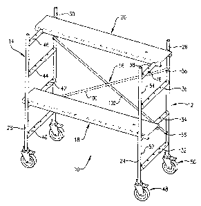
FIG. 4 is a perspective view of scaffolding constructed in accordance with a
preferred embodiment of the present invention and including a plurality of
open-slotted
ledgers for supporting walkboards with a pair of walkboards shown in a stepped
arrangement;
FIG. 5 is a fragmentary enlarged perspective view of the scaffolding shown
in FIG. 4 illustrating the slots of one of the ledgers and shown with one
walkboard in the
center position;
FIG. 6 is a fragmentary enlarged elevational view of the scaffolding shown
in FIG. 4 illustrating a wooden walkboard plank coupled to the ledger with an
elongated
headed fastener extending into one of the slots of one of the ledgers and a
pair of metal
walkboards coupled to another one of the ledgers;
FIG. 7 is a fragmentary enlarged sectional view of the scaffolding taken
substantially along line 7-7 of FIG. 6 illustrating the pair of walkboards in
an adjacent
relationship on the ledger with one of the support posts shown in phantom; and
FIG. 8 is a fragmentary perspective view of the scaffolding shown in FIG. 4
illustrating one of the walkboards in the storage position.
4
CA 02449276 2003-11-13
DETAILED DESCRIPTION OF THE PREFERRED EMBODIMENTS
FIG. 1 illustrates scaffolding 10 constructed in accordance with a preferred
embodiment of the present invention and configured for elevating a worker (not
shown)
above a floor or ground surface (not shown). The illustrated scaffolding 10 is
a mobile (e.g.,
rollable) and portable (e.g., dimensioned and configured to be lightweight and
quickly and
easily disassembled for compact storage and transport) scaffolding. However,
the principles
of the present invention are not limited to this scaffolding configuration and
equally apply
to virtually any type of scaffolding so long as the scaffolding utilizes some
type of walkboard
supported by ledgers to elevate a worker. The illustrated scaffolding 10
broadly includes a
pair of ladder frames 12 and 14, cross bracing 16 coupling the frames 12,14
together, and a
plurality of walkboards 18, 20, and 22 (see FIGS. 4 and 6) removably supported
between the
frames 12,14.
The frames 12,14 are configured to cooperate to support one or more of the
walkboards 18,20,22 elevated above the floor or ground surface at various
intervals of
elevation. In this regard, each of the frames 12,14 includes a corresponding
pair of vertical
support posts 24, 26 and 28, 30, respectively, and a plurality of slotted
ledgers 32, 34, 36, 38
and 40, 42, 44, 46 coupled to and extending horizontally between the
corresponding support
posts 24,26 and 28,30, respectively. As will subsequently be described in
detail, the ledgers
32,34,36,38 and 40,42,44,46 are vertically spaced at the various intervals of
elevation and
one or more of the walkboards 18,20,22 can be removably supported between any
one of the
ledgers in the frame 12 and the complemental ledger in the frame 14.
Additionally, as
described in detail below, the walkboards 18,20,22 can be horizontally spaced
along the
supporting ledgers at several selected positions and maintained at the desired
position to
prevent undesired shifting of the walkboard out of the selected position.
Each of the frames 12,14 are virtually identically configured, therefore, only
the frame 12 will be described in detail with the understanding that the frame
14 is similarly
constructed. In more detail, each of the vertical support posts 24,26 of the
frame 12 are
generally cylindrical and tubular in configuration presenting a hollow,
generally round shaped
cross section. The lower ends of each of the posts 24,26 are open and
configured to receive
various attachment components, such as a corresponding caster 48 and 50,
respectively, as
will be subsequently described. The upper end of each of the posts 24,26 is
also open and
although not illustrated, could be configured with a shaft or a pin-receiving
aperture to
facilitate receipt of various attachment components (e.g., guard rails,
another frame, etc.).
5
CA 02449276 2003-11-13
For purposes that will subsequently be described, fixed to the inside of each
of the posts
24,26 is a pair of coupling pins 52, 54 and 56, 58, respectively. The
illustrated posts 24,26
are configured and dimensioned to provide portability to the frame 12. In this
regard, the
illustrated posts 24,26 are preferably formed out of four foot lengths of one
inch diameter
fifteen gauge steel tubing. However, the posts 24,26 could be formed of any
suitable material
having any suitable dimensions.
As previously indicated, the plurality of slotted ledgers 32, 34, 36, 38 are
coupled to the support posts 24,26 and extend horizontally therebetween. The
ledgers
32,34,36,38 are vertically spaced along the posts 24,26 at stepped intervals
of elevation. In
this regard, when the scaffolding 10 is assembled, the ledgers 32,34,36,38 can
function as
rungs to allow the worker to climb up the frame I2 to one or more of the
walkboards
18,20,22 supported thereon. In addition, as further detailed below, the
stepped configuration
of the ledgers 32,34,36,38 enable one or more of the walkboards 18,20,22 to be
supported
at various intervals of elevation to provide an adjustable work surface. As
detailed below,
each of the ledgers 32,34,36,38 is configured to support one or more of the
walkboards
18,20,22 in a selected position and prevent the supported walkboard from
undesired shifting
along the supporting ledger. Except as noted below, each of the ledgers
32,34,36,38 is
virtually identically configured, therefore, only the ledger 38 will be
described in detail with
the understanding that the ledgers 32,34,36 are similarly constructed.
In more detail, and as shown in FIG. 5, the ledger 38 is defined by a wall 60
that presents a generally inverted U-shaped vertical cross-sectional shape
having a hollow
interior. The wall 60 extends horizontally to generally define a longitudinal
ledger axis
(designated as A in FIG. 5). The wall 60 includes a pair of downwardly
extending flanges
60a and 60b interconnected by a web section 60c. For purposes that will be
subsequently
described, the flanges 60a,60b are spaced on either side of the ledger axis A
to define and
open bottom along the length of the ledger 38. As will be detailed below, it
is important that
the web section 60c be arcuate to define an arch between the flanges 60a,60b.
The outer
surface of the arcuate web section 60c presents an upper walkboard bearing
surface 62 spaced
from and extending along the ledger axis A. The walkboard bearing surface 62
is configured
to support one or more of the walkboards 18,20,22. At each end of the ledger
38, the web
section 60c is cut away (see FIGS. 5 and 7). In this manner, a portion of the
cylindrical
support posts 24,26 can be received between the flanges 60a,60b. This enables
the ledger 38
to be quickly, effectively and securely attached to the posts 24,26 during
assembly. For
6
CA 02449276 2003-11-13
example, this configuration facilitates a secure weld between the ends of the
ledger 38 and
the posts 24,26. Such a secure weldment at the ledger ends was difficult, if
not impossible,
to obtain with the prior art ledgers as illustrated in FIGS. 1-3. As will
subsequently be
described in detail, a plurality of slots 64, 66, 68, 70, and 72 are defined
in, and spaced along,
the arcuate web section 60c (see FIGS. 5 and 7).
The ledger 38 includes a pair of hooks 74 and 76 coupled to and extending
from the flange 60a (see FIGS. 5 and 8). As will be further detailed below,
the hooks 74,76
are each configured to support one of the walkboards 18,20 in a storage
position as shown
in FIG. 8. The illustrated hooks 74,76 are virtually identically configured,
therefore, only the
hook 74 will be described in detail, with the understanding that the hook 76
is similarly
constructed. The hook 74 includes a shank 78 and a head 80 fixed to the shank
78. The
shank 78 extends from the flange 60a to space the head 80 from the flange 60a.
The hooks
74,76 are preferably included on the upper-most ledger to facilitate effective
support of
walkboards in the storage position, thus in the illustrated frame 12, the
ledgers 32,34,36 do
not include hooks. However, the hooks could be included on any or all of the
ledgers.
As previously indicated, the ledger 38 is configured to prevent undesired
shifting of a walkboard supported thereon. Each of the slots 64,66,68,70,72 is
configured and
dimensioned to receive a portion of the supported walkboard and prevent
shifting of the
walkboard along the ledger axis A. Each of the slots 64,66,68,70,72 are
virtually identical
in configuration and thus only the slot 64 will be described in detail with
the understanding
that the slots 66,68,70,72 are similarly constructed. In more detail, the slot
64 is defined in
the web section 60c by a plurality of slot-defining edges including a pair of
recessed edges
82 and 84 and a pair of abutment edges 86 and 88 (see FIGS. 5 and 7). Each of
the recessed
edges 82,84 are spaced below the bearing surface 62 and extend along,
generally parallel to,
the ledger axis A. Each of the abutment edges 86,88 project substantially
perpendicularly
from each of the recessed edges 82,84 to present a generally orthogonal shape
for the slot 64.
Each of the abutment edges 86,88 extends vertically to the bearing surface 62
so that each
of the abutment edges 86,88 is substantially perpendicular to the ledger axis
A. As
previously indicated, the web 60c is arcuate presenting an arch between the
flanges 60a,60b.
This arcuate configuration cooperates with the recessed nature of the edges
82,84 and the
perpendicular alignment of the edges 86,88 to provide a prominent and secure
abutment
surface along each of the abutment edges 86,88. As will be subsequently
detailed below, the
abutment surfaces engage a portion of a walkboard supported on the ledger 38
to prevent
7
CA 02449276 2003-11-13
undesired shifting of the supported walkboard along the ledger axis A. For
purposes that will
be further described below, the slot 64 is open between the edges 82,84,86,88
and
communicates with the hollow interior of the ledger 38 and the open bottom
defined between
the flanges 60a,60b. In this regard, the open slot 64 allows materials to pass
from the bearing
surface 62 through the ledger and drain out the open bottom thereof. For
example, during
assembly, exterior paint does not gather in the slot and thus does not inhibit
the function of
the abutment surfaces. Furthermore, debris that might otherwise accumulate on
the bearing
surface 62 (e.g., joint compound, putty, mud, etc.) can drain through the
ledger 38 and out
the open bottom thereof rather than collecting in the slot 64 as was
problematic in the prior
art of FIGS. 1-3.
The frame 12 is a mobile scaffolding frame and includes the previously
indicated casters 48,50. The casters 48,50 are virtually identically
configured and therefore
only the caster 48 will be described in detail with the understanding that the
caster 50 is
similarly constructed. The caster 48 is swively received in the open lower end
of the post 24
of the frame 12. In one manner known in the art, the caster 48 includes a
caster housing 90,
a stub shaft 92 swively coupled to the housing 90, a wheel 94 rollably
supported in the
housing 90, and a foot brake 96 operable to selectively prevent the wheel 94
from rolling.
The caster housing 90 supports the post 24 on the wheel 94. The stub shaft 92
is removably
received in the open lower end of the post 24 and is configured to be locked
in the post 24.
For example, the illustrated shaft 92 includes an aperture (not shown) that
aligns with
apertures formed in the lower end of the post 24. In this manner, a retaining
pin 98 can be
inserted through the post 24 and the stub shaft 92 to retain the shaft in the
lower end of the
post 24. The stub shaft 92 includes a bearing ring formed in its lower end
that carries a
bearing (not shown) to allow the caster housing 90 and thus the wheel 94 to
swivel relative
to the stub shaft 92 while still supporting the weight of the frame 12. The
foot brake 96 can
be pivoted into and out of a locking position (not shown) wherein the brake 96
communicates
with the wheel 94 to prevent the wheel 94 from rolling. It is within the ambit
of the present
invention to utilize various alternatively configured means for providing
mobility to the
scaffolding 10 that can be selectively prevented. One such suitable
alternative is the braking
system disclosed in pending application for U.S. Letters Patent Serial No. ,
filed
October 15, 2002, entitled MOBILE SCAFFOLDING BRAKE (sharing a common inventor
with the present application), which is hereby incorporated by reference
herein as is necessary
for a full and complete understanding of the present invention.
8
CA 02449276 2003-11-13
As previously indicated, the frame 12 is a lightweight portable scaffolding
frame (e.g., formed of 15 gauge steel tubing having a one inch diameter and
being four foot
in length). However, the principles of the present invention could be applied
to virtually any
type of scaffolding frame and are not limited to mobile, portable type frames.
For example,
various suitable alternative frames are disclosed in pending application for
U.S. Letters
Patent Serial No. 09/967,733, filed September 29, 2001, entitled MULTIPURPOSE
FRAME
ASSEMBLY (sharing a common inventor with the present application), which is
hereby
incorporated by reference herein as is necessary for a full and complete
understanding of the
presentinvention.
As indicated above, the frame I4 is configured in a manner similar to the
frame 12 detailed above. The illustrated frames 12,14 are removably coupled
together by
the cross bracing 16. Particularly, in one manner known in the art, the
bracing 16 is a scissor-
type brace including a pair of pivotally connected rods 100 and 102 (see FIG.
4). The rods
100,102 pivot relative to each other to provide adjustability of the
horizontal spacing of the
frames 12,14. The ends of each of the rods 100,102 are configured to be
removably received
on the pins 52,54 and 56,58 of the posts 26,30, respectively. The pins
52,54,56,58 preferably
include some type of safety locking device to prevent the rods from
inadvertently sliding off
the pins. There are several types of such locking devices known in the art.
For example,
various suitable locking devices are disclosed in U.S. Letters Patent No.
6,471,003, issued
October 29, 2002, entitled UTILITY SCAFFOLDING HAVING SAFETY FEATURES
(sharing a common inventor with the present application), which is hereby
incorporated by
reference herein as is necessary for a full and complete understanding of the
present
invention. The illustrated scaffolding 10 preferably includes bracing on one
side only to
enable a worker open access to the walkboards supported on the scaffolding
from the other
side. Accordingly, the cross bracing 16 is coupled to the vertical posts 26
and 30. However,
it is within the ambit of the present invention to utilize various
alternatives for coupling the
frames 12,14. For example, the frames could be joined with cross bracing on
each side of
the scaffolding. Additionally, the frames could be joined with a nonremovable
and/or folding
support bracing as is known in the art.
As previously indicated, the frames 12,14 cooperate to support one or more
of the walkboards 18,20,22 elevated above the floor or ground surface at
various intervals
of elevation. The walkboards 18,20,22 are configured to be removably supported
between
any one of the ledgers in the frame 12 and the complemental ledger in the
frame 14. The
9
CA 02449276 2003-11-13
walkboards 18,20,22 can be horizontally spaced along the supporting ledgers at
one of
several positions and maintained at the desired position to prevent undesired
shifting of the
walkboard out of the selected position. The walkboards 18 and 20 are virtually
identical in
configuration and thus only the walkboard 18 will be described in detail with
the
understanding that the walkboard 20 i s similarly constructed. The walkboard
22 is somewhat
different in configuration and will be described separately below.
In more detail, and as shown in FIGS. 4-8, the illustrated walkboard 18 is a
formed metal-type walkboard integrally formed from a single sheet of material
(e.g.,
aluminum, steel, etc.) presenting a support surface 104 and a pair of sidewalk
106 and 108
extending from the support surface. The support surface 104 is configured and
dimensioned
to support the worker above the floor or ground surface when the walkboard 18
is supported
horizontally between the frames 12,14. The illustrated support surface 104
includes a
keyhole 110 formed in the surface 104 adjacent one end. The keyhole 110 is
configured and
dimensioned to receive one of the hooks 74,76 when the walkboard 18 is in a
storage position
as illustrated in FIG. 8. Particularly, the head 80 of the hook 74 is received
through the
keyhole 110 so that the walkboard 18 hangs on the shank 78 of the hook 74. In
this manner,
the walkboard 18 can be conveniently stored on the scaffolding 10 in a quickly
accessible
manner when the walkboard 18 is not in use. The sidewalls 106,108 extend
vertically
downward from the support surface 104 and each include a bottom rail 106a and
108a,
respectively. The rails 106a,108a provide a smooth bottom surface free from
sharp edges and
corners exposed on the exterior of the walkboard 18.
As shown in FIG. 5, the walkboard 18 is not as wide as the ledger 38 and in
fact can be placed in several different positions along the ledger 38.
Accordingly, as
indicated above, the walkboard 18 includes structure that engages one or more
of the slots
in the supporting ledgers to prevent the walkboard 18 from undesired shifting
of the
walkboard 18 along the ledger axis A and out of the selected position. In the
illustrated
walkboard 18, this structure includes a pair of coupling margins 112 and 114
formed by
cutouts in the sidewall 106, a pair of coupling margins 116 and 118 formed by
cutouts in the
sidewall 108, and portions of the vertical sidewalls 106 and 108 adjacent the
cutouts. In
more detail, each of the margins 112,114,116,118 is configured to receive the
web section
60c and at least a portion of the flanges 60a,60b therein when the walkboard
18 is supported
on the ledger 38. In the illustrated sidewalls 106,108 the margins
112,114,116,118 are
formed in the vertical portion of the sidewalk 106,108 and in the rail
portions 106a,108a.
CA 02449276 2003-11-13
The margins 112,114, I 16, I I 8 each include a horizontal ridge 112a, 114a,
116a, and 118a,
respectively (see FIG. 8), that is formed in the vertical portion of the
corresponding sidewall
106,108 and that extends generally parallel to the support surface 104. As
shown in FIG. 7,
the illustrated slots 64,66,68,70,72 are spaced along the ledger 38 so that
each slot is spaced
from at least one other slot the width dimension of the walkboard 18. In the
illustrated ledger
38, the middle slot 68 is spaced from each of the end slots 64,72 the width of
the walkboard
18 and the slots 66,70 are spaced apart the width of the walkboard 18. In this
manner, when
the walkboard 18 is supported on the ledger 38 and the web section 60c is
received in the
corresponding margins 112,116, the ridges 112a,116a each engage the recessed
edges of one
of the slots (e.g., the slots 66 and 70 in FIG. 5 and the slots 64 and 68 in
FIGS. 6 and 7).
When the ridges 112a,116a engage the recessed edges of the corresponding
slots, the inside
and outside surfaces of the vertical portion of the corresponding sidewall
106,108 that is
adjacent the ridges 112a,116a (e.g., the portion of the sidewall 106 or 108
just above the
ridge) engages one of the abutment edges of the corresponding slot to prevent
shifting of the
walkboard 18 along the ledger axis A of the ledger 38. For example, as shown
in FIGS. 6
and 7, the inside surface of the vertical portion of the sidewall 106 engages
the abutment edge
88 of the slot 64 to prevent the walkboard 18 from shifting along the ledger
axis A toward
the vertical post 26. In a similar manner, shifting of the walkboard 18 toward
the vertical
post 24 is prevented by engagement of the inside surface of the sidewall 108
and the
abutment edge of the slot 68.
As shown in FIG. 7, the sidewalk 106,108 of the walkboard 18 and the slots
64,66,68,70,72 are cornplementally configured and dimensioned so that two
walkboard
sidewalk can be received in a single slot (e.g., in the middle slot 68 when
two walkboards
are supported adjacent one another on the same ledger). It is preferred that
the abutment
edges (e.g., the edges 86,88) orthogonally engage as much of the sidewall of
the walkboard
18 as feasible to optimize the shift prevention function. Accordingly, in the
illustrated
scaffolding 10, the ridges 112a,114a,116a,118a engage the recessed edges of
the slots and
thereby support the weight of the walkboard 18. Additionally, the arcuate web
section 60c
is arched sufficiently to facilitate a deeper abutment edge (e.g., preferably
greater than one-
eighth inch recess from the bearing surface 62). In this manner, when a worker
applies
pressure to the walkboard 18, the walkboard does not "jump" the abutment edge
and fall out
of the slot allowing undesired shifting of the walkboard along the ledger, as
was problematic
with the prior art illustrated in FIGS. 1-3. In the illustrated scaffolding
10, the margins
11
CA 02449276 2003-11-13
112a,114a,116a,118a also are configured to engage a portion of the flanges
60a,60b to
prevent shifting of the walkboard perpendicular to the ledger axis A.
It is within the ambit of the present invention to utilize variously
configured
walkboards having alternative coupling structure between the walkboard and the
slotted
S ledger. For example, the walkboard sidewalls do not need to engage the
recessed edges of
the slots, but rather the walkboard could be supported on the bearing surface
of the ledger as
long as a portion of the sidewall extends below the bearing surface
sufficiently to engage a
portion of the abutment edges. Additionally, the sidewalk do not need to be
able to engage
the flanges of the ledger. however, it is important that the walkboard include
some structure
operable to cooperate with the slot to prevent undesired shifting of the
walkboard along the
ledger.
One example of a suitable alternatively configured walkboard is the walkboard
22 as shown in FIG. 6. The walkboard 22 comprises a wooden plank-type
walkboard
presenting a support surface 120 configured and dimensioned to support the
worker above
the floor or ground surface when the walkboard 22 is supported horizontally
between the
frames 12,14. Unlike the previously described walkboards 18,20, the walkboard
22 is fully
supported on the bearing surface of the respective ledgers. The walkboard 22,
like the
walkboard 18,20, is not as wide as the ledgers and thus can be positioned in
various
horizontal locations along the ledgers and thus includes structure to prevent
undesired
shifting along the ledger and out of the selected position. In the walkboard
22 this structure
includes a headed fastener 122 having a shank that extends below the support
surface 120 and
into one of the open slots in the supporting ledger. In this manner, the shank
can engage one
of the abutment edges of the slot to prevent shifting of the walkboard 22
along the ledger axis
A. The open slots enable the headed fastener 122 to extend into the hollow
interior of the
supporting ledger, facilitating a variety of applications. In this regard, the
fastener 122 could
be inserted into the walkboard 22 so that the headed portion extends out of
the open side of
the ledger between the flanges. In this manner, after the fastener 122 is
inserted into the
walkboard 22, the headed portion of the fastener 122 could be bent into
engagement with
either of the flanges or the underside of the web inside the hollow interior
of the ledger to
also prevent vertical shifting of the walkboard off of the ledger.
Additionally, the open slots
and open sided ledger facilitate the use of fasteners of various types and
dimensions to
prevent the walkboard 22 from shifting along the ledger. For example, the
fastener could
comprise a bolt-type fastener that extends through the walkboard and one of
the slots in the
12
CA 02449276 2003-11-13
ledger to receive a washer (e.g., against the flanges or the web) and a nut to
secure the
walkboard to the ledger in a more permanent manner (e.g., for applications
wherein the
scaffolding may be set up for longer periods of time, etc.).
In use, the scaffolding 10 is assembled by interconnecting the frames 12,14
with the cross bracing 16 and then supporting one or more of the walkboards
18,20,22 in the
desired position. During use, one or more of the walkboards 18,20,22 can be
quickly and
easily repositioned to accommodate a wide variety of applications. For
example, as shown
in FIG. 4, the walkboards 18,20 can be positioned in a. step configuration to
provide a multi-
level support surface. In this application, an outside and a middle slot
receive the walkboard
14 sidewalk to prevent the walkboard from shifting out of the desired
position. As shown in
FIG. S, a single one of the walkboards 18,20,22 can be utilized in a middle
position (e.g.,
supported in slots 66,70 of ledger 38). As shown in FIG. 7, the walkboards
18,20 can be
placed side-by-side on the same ledger (e.g., ledger 38) wherein the middle
slot 68 receives
one sidewall from each walkboard. As shown in FIG. 6, the walkboard 22 can be
used end-
to-end with another walkboard on adjacent ledgers (e.g., to span between
frames of adjacent
scaffolding sections, etc.). As shown in FIG. 8, when a walkboard (e.g. the
walkboard 18)
is not in use, the walkboard can be placed in the storage position on the
scaffolding 10 where
it is out of the way, yet easily accessible.
The preferred forms of the invention described above are to be used as
illustration only, and should not be utilized in a limiting sense in
interpreting the scope of the
present invention. Obvious modifications to the exemplary embodiments, as
hereinabove set
forth, could be readily made by those skilled in the art without departing
from the spirit of
the present invention.
The inventors hereby state their intent to rely on the Doctrine of Equivalents
to determine and assess the .reasonably fair scope of the present invention as
pertains to any
apparatus not materially departing from but outside the literal scope of the
invention as set
forth in the following claims.
13