Language selection

Search

Patent 2449395 Summary

Third-party information liability

Some of the information on this Web page has been provided by external sources. The Government of Canada is not responsible for the accuracy, reliability or currency of the information supplied by external sources. Users wishing to rely upon this information should consult directly with the source of the information. Content provided by external sources is not subject to official languages, privacy and accessibility requirements.

Claims and Abstract availability

Any discrepancies in the text and image of the Claims and Abstract are due to differing posting times. Text of the Claims and Abstract are posted:

  • At the time the application is open to public inspection;
  • At the time of issue of the patent (grant).
(12) Patent: (11) CA 2449395
(54) English Title: POP-UP MECHANISM TO RAISE THE TOP OF PIECES OF FURNITURE
(54) French Title: MECANISME REGLABLE DE SURELEVATION DE MOBILIER
Status: Expired
Bibliographic Data
(51) International Patent Classification (IPC):
  • A47B 13/00 (2006.01)
  • A47B 9/02 (2006.01)
  • A47B 13/08 (2006.01)
(72) Inventors :
  • CARPENTIER, GUY (Canada)
(73) Owners :
  • CARPENTIER, GUY (Canada)
(71) Applicants :
  • CARPENTIER, GUY (Canada)
(74) Agent:
(74) Associate agent:
(45) Issued: 2006-08-15
(22) Filed Date: 2003-11-26
(41) Open to Public Inspection: 2004-06-02
Examination requested: 2003-11-26
Availability of licence: N/A
(25) Language of filing: English

Patent Cooperation Treaty (PCT): No

(30) Application Priority Data:
Application No. Country/Territory Date
60/430,123 United States of America 2002-12-02

Abstracts

English Abstract

A pop-up mechanism working in parallel pairs used for lifting the tabletop part of a piece of furniture has a pair of cantilever arms joined together by an upper oblong member and a lower oblong member, both said upper oblong member and lower oblong member being parallel relative to each other and each being rotationally attached to opposite ends of said pair of cantilever arms.


French Abstract

Un mécanisme de surélévation en paires parallèles utilisé pour soulever la partie supérieure d'un meuble possède une paire de bras cantilever, reliés entre eux par un élément oblong supérieur et un élément oblong inférieur, ces deux élément oblong supérieur et élément oblong inférieur étant en parallèle l'un par rapport à l'autre et chacun étant fixé de manière rotationnelle aux extrémités opposées desdites paires de bras cantilever.

Claims

Note: Claims are shown in the official language in which they were submitted.


CLAIMS


1. A pop-up mechanism working in parallel pairs used for lifting the tabletop
part of a piece of
furniture and comprising:
a pair of cantilever arms joined together by an upper oblong member and a
lower oblong
member, bath said upper oblong member and lower oblong member being parallel
relative to
each other and each being rotationally attached to opposite ends of said pair
of cantilever
arms;
said pair of cantilever arms further rotationally attached to a brace that is
fixed to said piece of
furniture;
a biasing means connecting one point of said brace to one point of said lower
oblong member
to provide a near zero force requirement for lifting said tabletop;
predrilled holes to pass mechanical fasteners for holding a cross bar
generally added during
final assembly of said pop-up mechanism;
stoppers situated on said braces to stop said cantilever arms so that they can
come to a rest
at a given position.

2. A pop-up mechanism working in parallel pairs used for lifting the tabletop
part of a piece of
furniture as in claim 1 wherein:
said stoppers can be changed in position by repositioning said stoppers into
different stopper
holes.


Description

Note: Descriptions are shown in the official language in which they were submitted.


CA 02449395 2005-08-04
POP-UP MECHANISM TO RAISE THE TOP OF PlECE9 OF FURNITURE
BACKGROUNd OF THE INVENTION
Field of the Invention
This invention relates to the field of fold out or pop-up tables in general
but more
particularly to a mechanism integrated into a piece of furniture to make its
tap pop-up.
i~,ackgrouryd
Over the years a number of inventions have concerned themselves with the
integration of a table with a trunk ar similar types of boxlike containers. In
one
instance, a container nam~aliy found inside the trunk is taken out,
articulated in such a
way so as to change its shape into a tabletop which sits atop the trunk. Other
inventions have the tabletop folding upward and outward after the trunk lid is
opened,
sometimes integrating the table top with the iriteriar side of the trunk lid.
Other patents
disclose more far out Concepts such as patent 3,9~0,1'~5 by I~abinson which
discloses a small trailer which converhS into a picnic table and patent
4,589,9Q2 by
Starck which discloses a tabletop over a portable cooler.


CA 02449395 2005-08-04
These inventions do not provide the same functionality nor do they provide the
same
advantages as the invention disclosed herein.
SUMMARY OF THE INVENTION
It is a first abject of the present invention to provide a piece of furniture
with a pop-up
tabletop-
It is a second object of the present invention to provide far a pap-up
mechanism that
is reliable and easy to use.
It is a third object of the present invention to provide for a pop-up
mechanism which is
compact and can be shipped economically tc~ provide a cost advantage in
marketing
costs.
It is a final object of the present invention to provide far a pap-up
mechanism that
requires minimal effort on the part of the user to move the tabletop from one
position
to another,
In order to da sa, the tabletop is also the top of the trunk, chest or other
box like
piece of furniture and it moves upward and laterally in an offset position
relative to the
trunk using a system of cantilevered arms. The word piece of furniture is used
here to
represent any type of fur~nitur~, box or container.
2


CA 02449395 2005-08-04
The foregoing and other objects, features, and advantages of this invention
will
become more readily apparent from the following detailed description of a
preferred
embodiment with reference to the accompanying drawings, wherein the preferred
embodiment of the invention is shown and described, by way of examples. As
will be
realized, the invention is capable of other and different embodiments, and its
several
details are capable of modifications in various obvious respecks, all without
departing
from the invention. Accordingly, the drawings and description are to be
regarded as
illustrative in nature, and not as restrictive.
8R1>rF Dl=SCRIPTION aF THE DRAWINGS
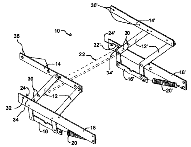
Fig. 'I Is a perspective elevational view of a pair of pop-up mechanisms.
Fig. 2 Is a side elevational view of a piece of furniture where the pop-up
mechanism
is in an open configuration with the top of the piece of furniture raised.
Fig. 3 Is a side elevational view of a piece of furniture where the pop-up
mechanism
is in an closed configuration with the top of the piece of furniture lowered.
bEtAILED DESCRIPTION OF THE PREFERRED EMBGDIMENT
3


CA 02449395 2005-08-04
A, pop-up mechanism 10, usually found in pairs with one mechanically fastened
to one
side of a piece of furniture 26 and the other fixedly etkached to an opposite
side sa
that they are parallel to each other.
Each pop up mechanism 10 has a pair of cantilever arms 12,12' which are joined
together by an upper ablartg member 1~,9~' and a lower oblong member 16,16'
both
being parallel relative to each other and each being natationally attached to
apposite
ends of the pair of cantilever arms 12, 12'. The pair of cantilever arms
12,12' is
further rotationally engaging a brace 18, 1$" which is fixedly attached to one
side of a
piece of furniture 26 (Eig. 2-3). A biasing means 20, 20' connects one point
of the
brace 1», 18' to one point of the lower oblong place 9 6, 16' in order to
provide a near
zero force requirement for lifting a tabletop 28. The two pop up mechanisms 10
are
joined together by way of a crass bar 22 (dotted lines) which is normally
mechanically fastened to the cantilever arms 12,12' using predrilled holes 30,
30' to
pass mechanical fasteners. l'he crass bar 2Z thus installed allows for each
otherwise
separate pop up mechanisms 10 to work in unison and is selected by a craftsman
during final assembly of the pop-up mechanism 10 according to the size of the
piece
of furniture 26 and also, to some extent to provide a match in wand essence
with the
rest of the piece of furniture. The cross bar 22 is not essential to the
workings of the
pop up mechanism 10 but it does help in making if work more reliably. By
providing
4


CA 02449395 2005-08-04
with only a pair of pop..up mechanisms 10, without the cross bar 22 an economy
in
shipping can be achieved.
A pair of stoppers 24, 2~' inserted into stopper holes 32, 32' situated on the
braces
18, 18' stop the cantilever arms 12, 12' so that they can come to a rest at ~
liven
position. That position can be changed by repositioning the stoppers 2~4, 24'
into a
different stopper hole 34, 34'. Each of the cantilever arm 12,12' is shaped
like a
hockey stick which allows the pop-up mechanism 10 full motion as well as to
reduce
the stn3ss on the biasing means fib, 20'. The upper oblong members 14, 1~'
have
predilled top fasteners holes 36, 38' through which mechnical fasteners pass
in order
to connect with wooden braces (not shown) themselves being part of the
tabletop 28.
The upper oblong members 16, 16' could alternatively be a L ~ shaped so that
the
part making contact with the tabletop 28 would have predrilled holes to pass
mechanical fasteners therethraugh.
In Fig. 2, the tabletop 28 is in its fully raised and extended configuration
where it is
resting in an overhanging, offset position in relation to the piece of
furniture 26. In
Fig. 3, the tabletop 28 is in the lowerad position. The tabletop x8 can be
used as part
of a coffee table whore it generally Pies low and unobtrusively to then be
raised and
brought closer to the user due to its being offset. It can also be used in a
bedroom in
lieu of a nightstand since the tabletop 28 only needs to be brought near a bed
when in


CA 02449395 2005-08-04
use and is afiherwis~ set same disfiance away Pram the bed.
lE? 04/08/2005 ~ 8~23 ~5143~68611 yeceived

Representative Drawing
A single figure which represents the drawing illustrating the invention.
Administrative Status

For a clearer understanding of the status of the application/patent presented on this page, the site Disclaimer , as well as the definitions for Patent , Administrative Status , Maintenance Fee  and Payment History  should be consulted.

Administrative Status

Title Date
Forecasted Issue Date 2006-08-15
(22) Filed 2003-11-26
Examination Requested 2003-11-26
(41) Open to Public Inspection 2004-06-02
(45) Issued 2006-08-15
Expired 2023-11-27

Abandonment History

There is no abandonment history.

Payment History

Fee Type Anniversary Year Due Date Amount Paid Paid Date
Request for Examination $200.00 2003-11-26
Application Fee $150.00 2003-11-26
Maintenance Fee - Application - New Act 2 2005-11-28 $50.00 2005-10-27
Final Fee $150.00 2006-06-08
Maintenance Fee - Patent - New Act 3 2006-11-27 $50.00 2006-10-23
Maintenance Fee - Patent - New Act 4 2007-11-26 $50.00 2007-10-19
Maintenance Fee - Patent - New Act 5 2008-11-26 $100.00 2008-10-20
Maintenance Fee - Patent - New Act 6 2009-11-26 $100.00 2009-10-19
Maintenance Fee - Patent - New Act 7 2010-11-26 $100.00 2010-10-20
Maintenance Fee - Patent - New Act 8 2011-11-28 $100.00 2011-10-17
Maintenance Fee - Patent - New Act 9 2012-11-26 $100.00 2012-10-24
Maintenance Fee - Patent - New Act 10 2013-11-26 $125.00 2013-10-23
Maintenance Fee - Patent - New Act 11 2014-11-26 $125.00 2014-10-28
Maintenance Fee - Patent - New Act 12 2015-11-26 $125.00 2015-10-16
Maintenance Fee - Patent - New Act 13 2016-11-28 $125.00 2016-10-24
Maintenance Fee - Patent - New Act 14 2017-11-27 $125.00 2017-10-27
Maintenance Fee - Patent - New Act 15 2018-11-26 $225.00 2018-10-23
Maintenance Fee - Patent - New Act 16 2019-11-26 $225.00 2019-10-24
Maintenance Fee - Patent - New Act 17 2020-11-26 $225.00 2020-10-15
Maintenance Fee - Patent - New Act 18 2021-11-26 $229.50 2021-11-12
Maintenance Fee - Patent - New Act 19 2022-11-28 $229.04 2022-10-25
Owners on Record

Note: Records showing the ownership history in alphabetical order.

Current Owners on Record
CARPENTIER, GUY
Past Owners on Record
None
Past Owners that do not appear in the "Owners on Record" listing will appear in other documentation within the application.
Documents

To view selected files, please enter reCAPTCHA code :


To view images, click a link in the Document Description column. To download the documents, select one or more checkboxes in the first column and then click the "Download Selected in PDF format (Zip Archive)" or the "Download Selected as Single PDF" button.

List of published and non-published patent-specific documents on the CPD .

If you have any difficulty accessing content, you can call the Client Service Centre at 1-866-997-1936 or send them an e-mail at CIPO Client Service Centre.


Document
Description 
Date
(yyyy-mm-dd) 
Number of pages   Size of Image (KB) 
Maintenance Fee Payment 2020-10-15 2 52
Abstract 2003-11-26 1 15
Claims 2005-08-04 1 27
Description 2005-08-04 6 132
Claims 2003-11-26 2 52
Description 2003-11-26 6 207
Representative Drawing 2004-01-23 1 15
Drawings 2003-11-26 2 54
Cover Page 2004-05-07 1 39
Maintenance Fee Payment 2021-11-12 2 55
Maintenance Fee Payment 2022-10-25 2 45
Claims 2005-11-03 1 24
Representative Drawing 2005-12-06 1 15
Cover Page 2006-07-18 1 40
Prosecution-Amendment 2005-02-07 4 154
Assignment 2003-11-26 2 117
Correspondence 2003-12-23 1 13
Prosecution-Amendment 2005-09-19 2 42
Prosecution-Amendment 2005-08-04 11 233
Fees 2007-10-19 1 24
Fees 2005-10-27 1 25
Prosecution-Amendment 2005-11-03 4 76
Maintenance Fee Payment 2017-10-27 1 27
Correspondence 2006-06-08 1 22
Fees 2006-10-23 1 23
Fees 2008-10-20 1 27
Correspondence 2010-04-06 1 20
Fees 2009-10-19 1 24
Maintenance Fee Payment 2018-10-23 1 27
Fees 2010-10-20 1 25
Correspondence 2014-10-28 1 27
Fees 2014-10-28 1 27
Fees 2011-10-17 1 22
Fees 2012-10-24 1 22
Maintenance Fee Payment 2019-10-24 1 30
Fees 2013-10-23 1 22
Maintenance Fee Payment 2015-10-16 1 30
Maintenance Fee Payment 2016-10-24 1 24