Note: Descriptions are shown in the official language in which they were submitted.
CA 02449619 2003-11-17
A-3868
Apparatus for producing a printing form
The invention relates to an apparatus for producing a printing
form according to the preamble of claim ~..
Known apparatuses for producing a printing form use an
imagesetting-head_with_a radiati.on_s,ource, in particular with. _ ._..
a laser diode array. The radiation source is driven in
accordance with an image. When a laser is activated, an image
point or a non-image point is produced on a printing form
blank coated with a light-sensitive material. The printing
form blank is accommodated as a plate, film or in sleeve form
on a cylinder or is located on a flat support table. In order
to be able to cover the entire surface of a printing form
blank, the imagesetting head is moved relative to the printing
form blank. In order to increase productivity, it is known to
use a plurality of imagesetting heads in parallel. For this
purpose, the imagesetting heads are mounted on a common holder
and are positioned relative to the printing form blank
together in a linear guide, for example on a carriage. In the
case of operation of imagesetting heads equipped with laser
diode arrays, heat is produced, which has to be dissipated by
a cooling apparatus. In order to produce image points or non-
image points, use is made of optically imaging elements whose
properties are highly temperature-dependent. In order to
ensure that the image points or non-image points are placed
accurately on the printing form blank in the micron range, it
is necessary to control the temperature of the optoelectrical
subassemblies. For this purpose, use is normally made of a
streaming or flowing temperature control medium, which is led
to the imagesetting heads by means of lines. The temperature
of the temperature control medium is regulated or controlled
_1_
CA 02449619 2003-11-17
in such a way that the desired temperature is produced on the
optoelectronic subassemblies. An interfering variable which
appears during the control or regulation of the temperature is
the ambient temperature of the imagesetting head. In
particular if apparatuses for producing printing forms are
integrated into presses, severe fluctuations of the ambient
temperatures occur, which can be compensated for only
inadequately. The ambient temperature fluctuations
additionally effect longitudinal expansions in a holder for a
plurality of imagesetting heads, so that impermissible changes
occur in the distance of the optoelectronic subassemblies from
one another, which lead to image errors during imagesetting.
In order to stabilize the printing process, it is known to set
up presses or printing apparatuses in air-conditioned rooms.
Furthermore, it is known to encapsulate presses with respect
to the outside and to maintain a dedicated climate in the
interior. Such globally acting temperature control
apparatuses are not capable of satisfying the special
requirements in the temperature control of imagesetting
apparatuses, of which it is required that they operate
accurately in the micron range.
In further known solutions, temperature-sensitive
optoelectronic components are isolated thermally from possible
interfering sources. Solutions of this type are complicated
and need a large amount of installation space.
It is an object of the invention to develop an apparatus for
producing a printing form which permits improved temperature
control of components that can be influenced by temperature.
-2-
CA 02449619 2003-11-17
The object is achieved with an apparatus which has the
features as claimed in claim 1. Advantageous refinements
emerge from the subclaims.
As a result of the provision of a temperature control
arrangement for a holder of one or more imagesetting heads, it
becomes possible to control the temperature of the
surroundings of an imagesetting head, in. each case over a
large space. Furthermore, it is possible to deform the
holder, such as a crossmember, specifically in order to
compensate for impermissible bending. The temperature gradient
between an imagesetting head and its surroundings is reduced
considerably, so that the control of the temperature of an
imagesetting head and the optoelectronic components contained
therein can be carried out more quickly, more accurately and
with less use of a temperature control. medium. If only one
circuit for a temperature control medium, such as water, is
provided, flow can take place during flow and during return
both through the holder and the components of an imagesetting
head. Temperature-induced expansions and tolerances on the
imagesetting head, on the holder and on a positioning system
for an imagesetting head are reduced to a minimum. Assisted by
a housing which is encapsulated with respect to the outside,
virtually all imagesetting heads are always operated at a
constant temperature.
In the case of systems with spindle positioning of the
imagesetting heads, substantially no temperature-induced
longitudinal change takes place, so that 'the positioning
accuracy of an imagesetting head is improved. A constant
operating temperature of an imagesetting head also improves
the dissipation of heat from electronic components within an
imagesetting head.
-3-
CA 02449619 2003-11-17
In the case of systems where a plurality of imagesetting heads
are held jointly on a carriage, the distances between the
imagesetting heads do not change. As a result, no line
connection errors, as they are known, axe produced in the
printed image between two lines which are produced by
different imagesetting heads.
Controlling the temperature of the holder of imagesetting
heads also achieves a situation where the expenditure on lines
for the temperature control of components within an
imagesetting head is reduced. The ducts for circulation of a
temperature control medium in the holder can be used at the
same time as flow and return lines for controlling the
temperature of one or more imagesetting heads. The holder
itself represents a heat store which does not permit any rapid
temperature fluctuations. As a result, the temperature
control becomes more independent of fluctuations which are
caused by a temperature control unit itself or by other
interfering sources in the surroundings.
The temperature control medium provided for the holder can
advantageously be water, preferably with a corrosion-
prevention and/or antifreeze additive.
The invention is to be explained in more detail using
exemplarily embodiments. In the drawing:
fig. 1 shows a schematic drawing of a temperature control
system for an apparatus for producing a printing form,
fig. 2 shows a schematic drawing of a crossmember made of an
aluminum extruded section,
-4-
CA 02449619 2003-11-17
fig. 3 shows a schematic drawing of a crossmember made of gray
cast iron, and
figs 4, 5 show a schematic drawing relating to the
compensation of bending on a crossmember.
The schematic drawing illustrated in fig. 1 shows a carriage 1
on which two imagesetting heads 2, 3 are held at a fixed
distance-- A__ from each other.. The., ,carriage- 1 , runs in a., linear
guide between two side walls of a press. The carriage 1 is
coupled to a nut 4 of a spindle drive. The spindle 5 of the
spindle drive is connected to a stepping motor 6. Using the
stepping motor 6 and the spindle drive, the carriage 1 can be
positioned in the lateral direction 7 between the side walls.
The direction 7 lies parallel to the axis of rotation of a
printing form cylinder 8 which is mounted in the side walls.
Clamped onto the circumferential surface of the printing form
cylinder 8 is a printing form blank 9. Each imagesetting head
2, 3 contains a laser diode array 10, 11, electronic
components for the power supply and control of the lasers, and
optoelectric components for focusing laser beams 12, 13 onto
the surface of the printing form blank 9. As the printing form
cylinder 8 rotates in the direction of the arrow 14, driven by
a motor M, the laser diode arrays 10, 11 are driven in
accordance with an image. In the process, image points
accepting printing ink are produced in tracks 15, 16 on the
printing form blank 9. During imagesetting, heat is produced
in the imagesetting heads 2, 3 and is dissipated by a water
cooling system. The water cooling system comprises a water
preparation device 17, flow lines 18, 19, return lines 20-23
and a flow duct 24 and return ducts 25, 26 within the carriage
1. The carriage 1 is implemented as a metallic extruded
section or as a casting, the ducts 24-26 having terminating
covers with connections for the flow and return lines 18-23.
-5_
CA 02449619 2003-11-17
The cooling water is brought to a predetermined temperature in
the water preparation device 17 and supplied to the
imagesetting heads 2, 3 via the flow line 18, the flow duct 24
and the flow line 19. In the imagesetting heads 2, 3, the
cooling water in each case flows through a heat exchanger to
which the components discharging heat are coupled thermally.
In the process, the water is heated and flows back to the
water preparation device 17 via the return lines 22, 23, the
return ducts 25, 26 and the return lines 20, 21.
As a result of the fact that the cooling water flows through
the ducts 24-26 both during flow and during return, the
carriage 1 assumes the temperature of the cooling water. The
carriage Z is a large-area component, so that the surroundings
1 approximately assume the temperature of the carriage 1 as a
result of heat exchange. Therefore, the imagesetting heads 2,
3 have their temperature pre-controlled by the carriage 1.
The temperature gradient between an imagesetting head 2, 3 and
the carriage 1 is small, so that the regulation of the
temperature of the imagesetting heads 2, 3 is improved. The
carriage 1 itself and the spindle 5 influenced by the
temperature of the carriage 1 have a low thermal expansion as
a result of the temperature control, so that no disruptive
positioning errors of the imagesetting heads 2, 3 in the
lateral direction 7 occur. Leading the lines to the water
preparation device 17 and the imagesetting heads 2, 3 is
simplified by including the ducts 24-26. In order to regulate
the cooling water temperature, a control device can be
provided, which is connected to the water preparation device
17. Furthermore, temperature sensors can be provided on the
imagesetting heads 2, 3 and on the carriage 1, being connected
to the control device.
-&-
CA 02449619 2003-11-17
Figures 2-4 show variants of crossmembers in which ducts
arranged vertically above one another are provided for cooling
water, in order additionally to compensate for the deflection
of a crossmember.
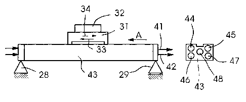
Fig. 2 illustrates a crossmember 27 which consists of an
aluminum extruded section. The crossmember 27 is held on a
fixed bearing 28 and a sliding bearing 29. The crossmember 27
has a longitudinal guide 30 for a carriage 31 with an
imagesetting head 32. The carriage 31 can be positioned
moving to and fro in the direction of the arrows 33, 34 during
imagesetting. The crossmember 27 has rectangular ducts 35-40
which are closed by end plates and through which, to some
extent, temperature-controlled water 41, 42 flows.
Fig. 3 shows a crossmember 43 of gray cast iron with bores 44-
47 closed by end plates.
The crossmembers 27, 43, the carriages 31 and the imagesetting
heads 32 have a weight which would cause deflection of the
crossmembers 27, 43. Furthermore, forces and moments which can
cause deflection act on a crossmember 27, 43. In order to
compensate for a deflection, the temperature of the water 41
in the ducts 35, 36 or bores 44, 45 located at the top can be
set to be higher than the water 42 in the lower ducts 37, 38
or bores 46, 47. Without any weight forces, the opposite
deformation, illustrated dashed in figure 4, of the
crossmember 27 or 43 would result. The opposite deformation
is based on the different longitudinal expansions of the
material of the crossmember 27, 43 in the regions above arid
below a neutral longitudinal center line. When the
crossmember 27, 43 is loaded with the normal weights 48,
forces and moments, the crossmember 27, 43 will be aligned
rectilinearly, as shown in fig. 5. Therefore, it is possible
_7_
CA 02449619 2003-11-17
to use crossmembers 27, 43 which have a low flexural rigidity,
which results in a saving of weight and material.
The temperature control of the crossmember 27, 43 can be
coupled to the temperature control of a carriage 1 or 31, so
that cooling water flows through the crossmember 27, 43, the
carriage 1, 31 and the imagesetting heads 2, 3, 32.
_g_
CA 02449619 2003-11-17
List of designations
1 Carriage
2, 3 Imagesetting head
4 Nut
Spindle
6 Stepping motor
7 Direction
8 Printing form cylinder
,_._._._...____._.___9printing form blank
..._.... _.
10, 11 Laser diode array
12, 13 Laser beam
14 Arrow
15, 16 Track
17 Water preparation device
18, 19 Flow line
20-23 Return line
24 Flow duct
25, 26 Return duct
27 Crossmember
28 Fixed bearing
29 Sliding bearing
30 Longitudinal guide
31 Carriage
32 Imagesetting head
33, 34 Arrow
35-40 Duct
41-42 Water
43 Crossmember
44-48 Bore
_g_