Note: Descriptions are shown in the official language in which they were submitted.
CA 02450588 2003-11-25
2
Description
MOTORIZED DRUM ROLLER WITH FIXED ENDS
Field of Invention
This invention relates to motorized conveyor rollers and particularly relates
to a motorized conveyor roller having a rotatable portion disposed between two
opposite stationary ends. The invention also relates to the method of barring
access to a motorized rotatable conveyor roller for driving a conveyor medium
by
disposing the motorized rotatable conveyor rollers between opposed generally
cylindrical stationary ends.
Background Art
A variety of conveyor roller systems have heretofore been designed and
utilized. A large variety of known conveyor roller systems comprise a
continuous
belt or conveyor medium which travels over a series of rollers. The rollers
can be
simple shafts on which may be mounted various forms of sprockets or drive
means for supporting the conveyor medium. Some advanced conveyor systems
utilize enclosed and sealed drive rollers with the drive motors contained
inside
the rollers themselves.
An example of such motorized conveyor roller is disclosed in U.S. Patent
No. 5,088,596 which teaches a motorized conveyor roller mounted in a conveyer
frame to support and propel articles from one end of the conveyor path towards
the opposite end. The conveyer roller includes a roller tube rotatably mounted
in
the conveyor frame and drive means contained inside the roller tube for
driving
the roller tube. The drive means includes a motor, a gear reducer assembly
operatively connected to the motor, and a drive member connected to the
outward shaft of the speed reducer for engaging and rotating the roller tube.
Furthermore there has been a concern by some to improve the safety
features of conveyor rollers and particularly motorized conveyor rollers. For
CA 02450588 2003-11-25
3
example, U.S. Patent No. 5, 642,799 illustrates a brake device for a conveyor
having two load supporting conveyor rollers rotatable to engage a load thereon
to
be transported along the conveyor. The load supporting rollers are movably
transversely to their axis of rotation by a load passing there over against a
resilient bias into engagement with a brake roller adapted to brake rotation
of the
conveyor rollers.
Moreover U.S. Patent No. 5,143,184 illustrates a safety shutdown system
for luggage conveyor systems.
Furthermore U.S. Patent No. 6, 082,528 teaches a conveyor roller.
There is, however, a need to improve the safety features of motorized
conveyor rollers.
It is a further object of this invention to provide an improved motorized
conveyor roller and method thereof.
It is an aspect of this invention to provide a motorized conveyor roller
having a rotatable portion and at least one stationary end.
Disclosure of Invention
It is a further aspect of this invention to provide a motorized conveyor
roller
for supporting and driving a conveyor medium comprising a hollow drum defining
a rotatable supporting surface having a cylindrical shape disposed between
said
first and second generally cylindrical stationary ends; said first and second
generally cylindrical stationary ends co-axially mounted to first and second
spaced apart stationary shafts respectively; one end of each of said
stationary
shafts disposed internally of said hollow drum for carrying drive means for
rotating said hollow drum between said generally cylindrical stationary ends.
It is yet a further aspect of this invention to provide a method of barring
access to a motorized rotatable conveyor roller for driving a conveyor medium
by
CA 02450588 2011-04-18
4
disposing said motorized rotatable conveyor roller between opposed generally
cylindrical stationary ends.
These and other objects and features of the invention shall now be
described in relation to the following drawings.
Brief Description of Drawings
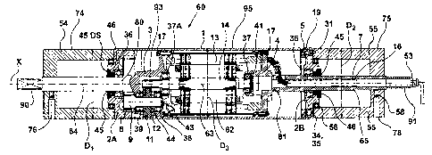
Fig. I is a full cross-sectional view of a motorized conveyor roller.
Fig. 2 is an end view of Fig. 1.
Detailed Description of the Preferred Embodiments
In the description, which follows, like parts are marked throughout the
specification and the drawings with the same respective reference numerals.
The
drawings are not necessarily to scale and in some instances proportions may
have
been exaggerated in order to more clearly depict certain features of the
invention.
Fig. I generally illustrates the motorized conveyor roller 60 having a
rotatable portion, hollow drum, a roller tube 1. The rotatable portion I is
disposed
between a first generally cylindrical stationary end or portion 54 and a
second
generally cylindrical stationary end or portion 55. The first and second
cylindrical
stationary 25 ends 54 and 55 define two opposite stationary ends 54 and 55.
The rotatable portion I comprises a rotatable displaceable roller tube as
shown. The roller tube 1 includes a motor generally depicted as 62. The motor
comprises a stator 13 and rotor 14. The rotor 14 defines a rotatable shaft 63
which is received by ball bearings 37 and 37A for rotation thereabouts.
More specifically each of the stationary ends 54 and 55 are co-axially
disposed about a first stationary shaft 64 and a second stationary shaft 65 as
shown in Fig. 1. First and second stationary shafts 64 and 65 are co-axially
CA 02450588 2003-11-25
disposed with rotatable shaft 63 about an axis X. First stationary shaft 64,
second stationary shaft 65 and rotatable shaft 63 define a central axis X.
In other words the first and second spaced stationary shafts 64 and 65
5 carry the two stationary ends 54 and 55 respectively. Each of the stationary
ends
present a generally cylindrical surface 74 and 75 presenting an outer diameter
D1, D2 respectively. Furthermore each of the first and second stationary ends
54
and 55 are secured to the stationary shafts 64 and 65 by a variety of means
including socket headset screws 58 located in set screw holes 76 and 78 as
shown. Alternate securing means can be used to secure the first and second
stationary ends 54 and 55 to the stationary shafts 64 and 65 such as keyways,
friction fit splines, adhesive and the like.
Furthermore the rotatable shaft 63 is carried by the motor 62.
The hollow drum 1 defines a rotatable supporting surface having the
cylindrical shape as shown disposed between the first and second generally
cylindrical stationary ends 54 and 55. One end 80 and 81 of each of the
stationary shafts 64 and 65 respectively are disposed internally of the hollow
drum 1 for carrying the drive means which consists of the motor 62 for
rotating
the hollow drum 1 between the generally cylindrical stationary ends,54 and 55.
More specifically the second shaft 65 comprises a hollow shaft 7 having a
cable passage 16 for receiving an electrical cable electrically connected to
the
motor 62 as shown. One end of the hollow drum I includes an end flange 2A
while the other end of the hollow drum 1 includes end flange 2B. Both end
flanges 2A and 2B are press fit or connected to the outer shell of the hollow
drum
1.
End flange 2A includes a double seal adapter 45DS and oil seal 46 as well
as bearing rings 45. Furthermore ball bearings 36 are also associated with end
flange 2A.
CA 02450588 2003-11-25
6
Moreover end flange 2B includes ball bearings 36, a mounting ring 5 and
spring ring 19. A filler plug 34 and washer 35 are also disclosed. A socket
head
cap screw 31 is utilized to secure the end flange 2B to the mounting ring 5
and
spring ring 19 together. Furthermore bearing race 45 and oil seal 46 with
bearings 56 are shown.
The other ends 90 and 91 of stationary shafts 64 and 65 have a cross-
section which permits the other ends 90 and 91 of the first and second
stationary
shafts 64 and 65 to be held by a shaft holder on the like that will register
with the
square cross-section for positive securement. In Fig. 2 the other end 90 and
91
presents a generally square cross-section so as to prevent rotation of the
stationary shafts 64 and 65. The other end 91 of second stationary shaft 65
illustrates a PG9 connector 53.
Moreover one end 80 of fixed shaft 64 presents a gear housing 3. One
end 81 of the second shaft 65 presents a motor flange 4. Furthermore locking
disk 41 is disposed in the vicinity of the motor flange 4. Each of the gear
housing
3 and motor flange 4 present ball bearings 37A and 37B respectively which
permit free rotation of the rotor or rotational shaft 14. The ends of gear
housing 3
and motor flange 4 present securing means 17 to secure the stator 13 thereto
as
shown. More specifically the securing means 17 comprises in one example
socket head cap screws as shown.
The rotatable shaft 63 which defines the rotor 14 has at one end thereof a
pinion 93 for rotational engagement with gear 11. Gear 11 is press fit to
second
pinion 9 which rotationally engages internal gear 8. The internal gear 8 is
presented by end flange 2A thereby causing the hollow shell 1 to rotate about
the
stator 13. The assembly further includes a distance ring 12 as shown. Moreover
snap ring 44, ball bearings 38 and snap ring 43 are shown.
The outer surface 95 of hollow drum 1 presents an outer diameter D3
which is slightly greater than the diameter of each of the generally
cylindrical
stationary ends D, and D2. Therefore a conveyor medium (not shown) will be
driven by the outer surface 95 of the rotatable portion 1 rather than the
outer
CA 02450588 2011-04-18
7
surface 74 and 75 of first and second stationary ends 54 and 55, since outer
surface 95 is slightly raised. Furthermore the outer surface 95 can include by
knurling or machining a spiral at each end toward the center or by covering
the
outer surface 95 with rubber so as to increase the co-efficient of friction
between
the surface 95 and conveyor.
Furthermore the gear 11, second pinion 9 and internal gear 8 define gear
means which is driven by the first pinion 93.
The invention described herein defines a method of barring access to a
motorized rotatable conveyor roller I which drives a conveyor medium by
disposing the motorized rotatable conveyor roller I between opposed generally
cylindrical stationary ends 54 and 55.
Accordingly if someone near the conveyor system accidentally touches the
end of the motorized conveyor roller 60, they will come into contact with the
stationary ends 54 and 55 thereby preventing any damage which may otherwise
occur where a person would come in contact with rotating parts which may cause
physical damage or catch any loose clothing drawing a person into the system.
Furthermore the invention described herein can be utilized to retrofit
existing motorized conveyor rollers having one end 90 and 91 of first and
second
stationary shafts 64 and 65 which are long enough to accommodate the addition
of a stationary ends 54 and 55 thereto. In other words, stationary ends 54 and
55
may comprise of adapters which are sufficiently sized so as to enable one to
attach the first and second stationary ends to the shafts 64 and 65 by
utilizing
securing means 58 as shown.
Moreover although the stationary ends 54 and 55 are shown as secured to
the first and second stationary shafts 64 and 65 it is possible to include
appropriate grooves within the shafts 64 and 65 to receive C-washers that
would
retain the stationary ends there between.
CA 02450588 2003-11-25
8
Typically there is a small gap between the ends of the first and second
stationary ends 54 and 55 and end flange 2A and end flange 2B. For example,
such gap may be in the vicinity of 0.04 inch although such example should not
be
interpreted as limiting but only as an example.
The invention described herein illustrates a rotatable roller having
cylindrical ends disengaged from the rotational movement of the rotational
roller.
Various embodiments of the invention have now been described in detail.
Since changes in and/or additions to the above-described best mode may be
made without departing from the nature, spirit or scope of the invention, the
invention is not to be limited to said details.