Language selection

Search

Patent 2450596 Summary

Third-party information liability

Some of the information on this Web page has been provided by external sources. The Government of Canada is not responsible for the accuracy, reliability or currency of the information supplied by external sources. Users wishing to rely upon this information should consult directly with the source of the information. Content provided by external sources is not subject to official languages, privacy and accessibility requirements.

Claims and Abstract availability

Any discrepancies in the text and image of the Claims and Abstract are due to differing posting times. Text of the Claims and Abstract are posted:

  • At the time the application is open to public inspection;
  • At the time of issue of the patent (grant).
(12) Patent: (11) CA 2450596
(54) English Title: TAILGATE TOOLBOX
(54) French Title: BOITE A OUTILS POUR HAYON ARRIERE
Status: Expired and beyond the Period of Reversal
Bibliographic Data
(51) International Patent Classification (IPC):
  • B60R 09/06 (2006.01)
  • B60R 05/04 (2006.01)
  • B60R 09/00 (2006.01)
  • B60R 09/055 (2006.01)
(72) Inventors :
  • AXELSON, GARTH (Canada)
(73) Owners :
  • GARTH AXELSON
(71) Applicants :
  • GARTH AXELSON (Canada)
(74) Agent:
(74) Associate agent:
(45) Issued: 2006-10-31
(22) Filed Date: 2003-11-25
(41) Open to Public Inspection: 2004-06-24
Examination requested: 2004-05-31
Availability of licence: N/A
Dedicated to the Public: N/A
(25) Language of filing: English

Patent Cooperation Treaty (PCT): No

(30) Application Priority Data:
Application No. Country/Territory Date
10/327,809 (United States of America) 2002-12-24

Abstracts

English Abstract

A toolbox assembly for mounting in the box of a pickup truck includes a rectangular casing with an open front end; a drawer slidable in said casing; a lock on said drawer for locking the drawer in the casing; a pair of L-shaped brackets for mounting on the floor of the box immediately rearwardly of the wheel wells, the brackets slidably receiving the casing; and a lock mechanism for releasably locking the casing in said brackets.


French Abstract

Un ensemble de boîte à outils pour le montage dans la benne d'une camionnette comprend un boîtier rectangulaire avec une extrémité avant ouverte ; un tiroir coulissant dans ledit boîtier ; un verrou sur ledit tiroir pour bloquer le tiroir dans le boîtier ; une paire de crochets en forme de L pour le montage sur le plancher de la benne immédiatement vers l'arrière des passages de roue, les crochets recevant de façon coulissante le boîtier ; et un mécanisme de verrouillage pour verrouiller de façon amovible le boîtier dans lesdits crochets.

Claims

Note: Claims are shown in the official language in which they were submitted.

I CLAIM:
1. A toolbox assembly for a pickup truck having a box defined by a floor, side
walls and a tailgate pivotally connected to the rear end of the box for
rotation
between closed and open positions, said toolbox comprising:
a casing including a top wall, a bottom wall, side walls, a rear end wall and
an
open front end;
a lockable drawer slidably mounted in said open front end for movement
between closed and open positions;
a pair of spaced apart brackets for mounting on the floor of the truck for
slidably receiving said casing having L-shaped cross sections and including
sides for
slidably receiving the side walls of the casing, and bases for securing the
brackets to
the floor of a pickup truck adjacent to side walls of a truck box; and
a lock mechanism for locking said casing in said brackets, whereby the
toolbox can be slid into said brackets and releasably locked in position on
the floor
of the truck box.
2. A toolbox assembly according to claim 1, including pins extending
outwardly from the sides of the casing, and first slots in said brackets for
slidably
receiving said pins to position the casing in said brackets.
3. A toolbox assembly according to claim 2, wherein said lock mechanism
includes loops extending outwardly from said rear wall of said casing for
receiving a
padlock; and second slots in said brackets for receiving said loops, whereby,
when
said loops are inserted through said slots, padlocks can be inserted into said
loops
to lock the toolbox in said brackets.
6

4. A toolbox assembly according to claim 3, wherein each said bracket is L-
shaped when viewed from above, the side of each bracket having a free end
containing said first slot for receiving said pin on the casing, and an end
wall
containing said second slot for receiving one said loop.
7

Description

Note: Descriptions are shown in the official language in which they were submitted.


CA 02450596 2003-11-25
TAILGATE TOOLBOX
BACKGROUND OF THE INVENTION
FIELD OF THE INVENTION
This invention relates to a toolbox assembly, and in particular to a toolbox
for
removable mounting in the box of a pickup truck.
In some jurisdictions, a firearm cannot legally be carried loose in a motar
vehicle, i.e. a firearm must be locked in a trunk, which is not available on a
pickup
truck, or carried in a locked container on or in the vehicle. Since the advent
of the
pickup truck a great many containers of various shapes and sizes have been
designed for mounting in the box of vehicles to carry tools and other valuable
items
or simply to protect things from the environment.
DISCUSSION OF THE PRIOR ART
Examples of containers for use on pickup trucks are disclosed by US Patents
Nos. 4;249,684, issued to K. Miller et al on February 10, 1981 4,266,821,
issued to
L.M. Gillet on May 12, 1981; 5,518,158, issued to W.L. Matlack on May 21,
1996;
5,634,577, issued to J.C. Pearson, Jr. et al on June 3, 1997; 5,988,473,
issued to
S.L. Hagan et al on November 23, 1999; 5,996,868, issued to A.C. Paradis on
December 7, 1999; 6,006,971, issued to C.R. Coleman et al on December 28,
1999;
6,068,319, issued to P. O'Brien on May 30, 2000; 6,077,007, issued to E.A.
Porter et
al on June 20, 2000; 6,203,087, issued to M. Lance et al on March 20, 2001 and
6,253,976, issued to C.R. Coleman et al on July 3, 2001
Many of the patented or commercially available containers are somewhat
complicated and/or difficult to mount on a vehicle. Moreover, to a large
extent,
existing toolboxes and other containers are designed for more or less
permanent
attachment to a vehicle. Thus, with a toolbox in place, certain areas of a
truck box
1

CA 02450596 2003-11-25
are not available for other purposes such as for mounting a fifth wheel hitch.
Fifth
wheels for pickup trucks are usually mounted between the wheel wells on the
floor
of a pickup truck box. A permanently mounted container near the tailgate of a
pickup truck can present difficulties with respect to the mounting of a hitch
or the
removal of the container when connecting a trailer to the vehicle.
GENERAL DESCRIPTION OF THE INVENTION
The object of the present invention is to provide a toolbox assembly which
permits the quick and easy mounting and removal of a toolbox from the box of a
pickup truck.
Accordingly, the invention relates to a toolbox assembly for a pickup truck
having a box defined by a floor, side walls and a tailgate pivotally connected
to the
rear end of the box for rotation between closed and open positions, said
toolbox
comprising:
a casing including a top wall, a bottom wall, side walls, a rear end wall and
an
open front end;
a lockable drawer slidably mounted in said open front end for movement
between closed and open positions;
a pair of spaced apart brackets for mounting on the floor of the truck for
slidably receiving .said casing; and
a lock mechanism for locking said casing in said brackets, whereby the
toolbox can be slid into said brackets and releasably locked in position on
the floor
of the truck box.
2

CA 02450596 2003-11-25
BRIEF DESCRIPTION OF THE DRAWINGS
The invention is described below in greater detail with reference to the
accompanying drawings, wherein:
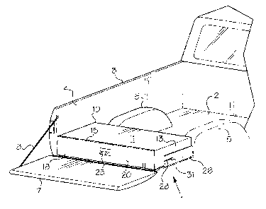
Figures 1 and 2 are isometric views of a portion of the rear end of a pickup
truck and a toolbox assembly in accordance with the irivention;
Figure 3 is an exploded, isometric view of the toolbox assembly of the present
invention; and
Figures 4 and 5 are exploded, isometric views of lock mechanisms used on
the toolbox assembly of Figs. 1 to 3.
DESCRIPTION OF THE PREFERRED EMBODIMENT
With reference to Figs. 1 and 2, the toolbox of the present invention which is
indicated generally at 1 is intended for use on the rear end of the floor 2 of
a
conventional pickup truck 3. The box of the truck includes sides 4 (one shown)
with
wheel wells 5 extending inwardly therefrom. A tailgate T is pivotally
connected to the
rear end of the floor 2 of the truck and is held in a roughly horizontal, open
position
by cables 8 (one shown) extending between the sides 4 of the truck box and the
top
ends of the tailgate.
The toolbox 1 includes a casing 10 formed of sheet metal or plastic. Thd
casing is defined by a top wall 11, a bottom wall 12 (Fig. 3), side walls 13
{one
shown), a rear wall 14 (Figs. 4 and 5) and an open front end 15. A drawer 18
is
slidably mounted in the casing 10 for movement between a closed position {Fig.
1 )
and an open position (Figs. 2 and 3). The drawer 18 includes a bottom wall 19,
a
front wall 20, a rear wall 21 and side walls 22. Rails 24 on the side wall 22
slide in
tracks {not shown) on the interior of the side walls 13 of the casing 10 for
opening
3

CA 02450596 2003-11-25
and closing the drawer. A conventional lock and operating handle combination
25
are provided in the front wall 20 of the drawer.
The toolbox 1 is removably mounted in the truck box using a pair of brackets
26. The brackets 26 are L-shaped in cross section and when viewed from above.
The bottom arms or bases 27 (Fig. 3) of the brackets 26 are bolted to the
filoor 2 of
the truck box. Slots 28 in free ends of the vertical, sides 30 of the brackets
26
receive pins 31 extending outwardly from plates 32 on the side walls 13 of the
toolbox casing 10 to position the toolbox in the truck.
As best shown in Fig. 4 the toolbox is releasably locked in position using a
lock assembly including loops 34 extending outwardly from plates 35 on the
rear wall
14 of the casing 10 near the corners thereof. When the casing 10 is slid into
the
brackets 26, the loops 34 extend through slots 36 in vertical ends 37 of the
brackets
26. A padlock (not shown) is used to releasably lock the toolbox in the
brackets 26.
Referring to Fig. 5, alternative lock assembly includes L-shaped brackets 39.
One arm 40 of each bracket 39 is spot welded or otherwise connected on the
rear
wall 14 of the casing 10 near a corner thereof. When the casing 10 is slid
into the
brackets 26, the other arms 41 of the brackets extend through the slots 36.
Holes
43 in the arms 41 define loops for receiving a padlock to lock the toolbox in
the
brackets 26.
Because the tailgate 7 of most pickup trucks is not exactly horizontal in the
open position (Figs. 1 and 2), i.e. the tailgate is inclined slightly upwardly
and
rearwardly, it would not be possible to open the drawer 18 if the casing 10
was
mounted directly on the floor of the truck box. Accordingly, a platform
defined by a
plurality.of transversely and longitudinally extending metal strips 45 and 46,
4

CA 02450596 2003-11-25
respectively, is provided on the bottom of the casing 10. The strips 45 and 46
are
welded or otherwise secured to the bottom of the casing 10. Of course, by
suitably
constructing the casing 10, e.g. with a thicker base, the platform can be
dispensed
with. However, it is more practical to provide a platform connected to the
bottom of
a more conventional casing 10,
With the above described toolbox construction and the location of the toolbox
on a truck, access to the drawer 18 is denied until the tailgate is opened.
Thus, a
locked tailgate and a locked toolbox provide a double measure of security.
When
the toolbox is mounted in the brackets 26, the bolts holding the brackets in
position
are not accessible.

Representative Drawing
A single figure which represents the drawing illustrating the invention.
Administrative Status

2024-08-01:As part of the Next Generation Patents (NGP) transition, the Canadian Patents Database (CPD) now contains a more detailed Event History, which replicates the Event Log of our new back-office solution.

Please note that "Inactive:" events refers to events no longer in use in our new back-office solution.

For a clearer understanding of the status of the application/patent presented on this page, the site Disclaimer , as well as the definitions for Patent , Event History , Maintenance Fee  and Payment History  should be consulted.

Event History

Description Date
Revocation of Agent Requirements Determined Compliant 2020-09-01
Time Limit for Reversal Expired 2013-11-26
Letter Sent 2012-11-26
Inactive: Late MF processed 2011-09-13
Letter Sent 2010-11-25
Grant by Issuance 2006-10-31
Inactive: Cover page published 2006-10-30
Pre-grant 2006-08-11
Inactive: Final fee received 2006-08-11
Notice of Allowance is Issued 2006-04-18
Letter Sent 2006-04-18
Notice of Allowance is Issued 2006-04-18
Inactive: IPC from MCD 2006-03-12
Inactive: Approved for allowance (AFA) 2006-03-08
Amendment Received - Voluntary Amendment 2005-11-10
Application Published (Open to Public Inspection) 2004-06-24
Inactive: Cover page published 2004-06-23
Letter Sent 2004-06-16
Request for Examination Received 2004-05-31
Request for Examination Requirements Determined Compliant 2004-05-31
All Requirements for Examination Determined Compliant 2004-05-31
Inactive: IPC assigned 2004-02-11
Inactive: First IPC assigned 2004-02-11
Application Received - Regular National 2004-01-12
Inactive: Filing certificate - No RFE (English) 2004-01-12
Small Entity Declaration Determined Compliant 2003-11-25

Abandonment History

There is no abandonment history.

Maintenance Fee

The last payment was received on 2005-10-18

Note : If the full payment has not been received on or before the date indicated, a further fee may be required which may be one of the following

  • the reinstatement fee;
  • the late payment fee; or
  • additional fee to reverse deemed expiry.

Patent fees are adjusted on the 1st of January every year. The amounts above are the current amounts if received by December 31 of the current year.
Please refer to the CIPO Patent Fees web page to see all current fee amounts.

Fee History

Fee Type Anniversary Year Due Date Paid Date
Application fee - small 2003-11-25
Request for examination - small 2004-05-31
MF (application, 2nd anniv.) - small 02 2005-11-25 2005-10-18
Final fee - small 2006-08-11
MF (patent, 3rd anniv.) - small 2006-11-27 2006-11-27
MF (patent, 4th anniv.) - small 2007-11-26 2007-11-09
MF (patent, 5th anniv.) - small 2008-11-25 2008-11-05
MF (patent, 6th anniv.) - small 2009-11-25 2009-11-19
MF (patent, 7th anniv.) - small 2010-11-25 2011-09-13
Reversal of deemed expiry 2010-11-25 2011-09-13
MF (patent, 8th anniv.) - small 2011-11-25 2011-09-13
Owners on Record

Note: Records showing the ownership history in alphabetical order.

Current Owners on Record
GARTH AXELSON
Past Owners on Record
None
Past Owners that do not appear in the "Owners on Record" listing will appear in other documentation within the application.
Documents

To view selected files, please enter reCAPTCHA code :


To view images, click a link in the Document Description column. To download the documents, select one or more checkboxes in the first column and then click the "Download Selected in PDF format (Zip Archive)" or the "Download Selected as Single PDF" button.

List of published and non-published patent-specific documents on the CPD .

If you have any difficulty accessing content, you can call the Client Service Centre at 1-866-997-1936 or send them an e-mail at CIPO Client Service Centre.


Document
Description 
Date
(yyyy-mm-dd) 
Number of pages   Size of Image (KB) 
Abstract 2003-11-24 1 13
Description 2003-11-24 5 194
Claims 2003-11-24 2 50
Drawings 2003-11-24 4 84
Representative drawing 2004-03-18 1 12
Claims 2005-11-09 2 47
Filing Certificate (English) 2004-01-11 1 169
Acknowledgement of Request for Examination 2004-06-15 1 176
Reminder of maintenance fee due 2005-07-25 1 109
Commissioner's Notice - Application Found Allowable 2006-04-17 1 162
Maintenance Fee Notice 2011-01-05 1 171
Late Payment Acknowledgement 2011-09-21 1 163
Maintenance Fee Notice 2013-01-06 1 170
Fees 2005-10-17 1 22
Correspondence 2006-08-10 1 29
Fees 2006-11-26 1 29
Fees 2007-11-08 1 25
Fees 2008-11-04 1 24
Fees 2011-09-12 1 46