Note: Descriptions are shown in the official language in which they were submitted.
CA 02450635 2007-01-16
1
DESCRIPTION
CONTINUOUS RIVETER AND CONTINUOUS RIVETING METHOD OF BLIND RIVETS
TECHNICAL FIELD
The present invention relates to a continuous riveter
capable of firing blind rivets (hereinafter referred to as
rivets) in succession to rivet sheet metal or the like, and to
a continuous riveting method of rivets.
BACKGROUND ART
The inventors of the present invention have filed a Japanese
patent application, JP 2003-103336 A, for a continuous riveter
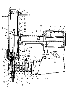
shown in FIGS. 12 through 34. This continuous riveter is composed
of a main body D, a driver section E, a rivet supplying section
F, and a valve section G. FIGS. 12 and 13 show the riveter with
a push button of a trigger valve released. FIGS. 14 through 19
show the riveter with the push button of the trigger valve
pushed.
The driver section E has a small-diameter oil cylinder 1
which branches away from the main body D to extend sideways and
a large-diameter air cylinder 3 which drives an oil piston 2 of
the oil cylinder 1.
The oil piston 2 serves as a piston rod of a piston 7
installed in the air cylinder 3, and the oil piston 2 and the
piston 7 are unitarily formed.
The oil cylinder 1 is communicated with a chuck cylinder 8
through a hole 18 leading to an oil chamber 16, which is a space
created between a jaw case piston 20 and a nose piston 28 in the
chuck cylinder 8.
Denoted by P2 is a second port for supplying compressed air
to a piston anterior chamber 4 of the air cylinder 3 and to an
air chamber 15 (FIG. 16) that is located between the nose piston
28 and a rod cover 17. The second port P2 is communicated with
CA 02450635 2007-01-16
2
a port f (FIG. 13), which is one of the exit side ports of an
operation valve 53.
Denoted by P1 is a first port for supplying compressed air
to a posterior chamber 5 (FIG. 14) that is positioned behind the
piston of the air cylinder 3. The first port P1 is communicated
with a port e, which is the other of the exit side ports of the
operation valve 53 described later.
Denoted by P3 is a third port for supplying, at an advanced
position of the piston 7 (FIG. 14), compressed air of the
posterior chamber 5 of the air cylinder 3 to a pilot air circuit
Y of the operation valve 53.
A storage case 47 of the rivet supplying section F is fixed
to the lower end of the air cylinder 3 with a pin 27.
The oil cylinder 1 and the chuck cylinder 8 of the main body
D are unitarily formed while positioned at approximately right
angles with respect to each other. A shank storing case 9 for
receiving a shank Ri, which is cut off of a blind rivet R, is set
in an upper part of the interior of the main body D. The rivet
supplying section F is attached to a lower part of the exterior
of the main body D.
A vacuum ejector 12 for vaccumizing the interior of the
shank storing case 9 is attached to the upper end of the shank
storing case 9.
The chuck cylinder 8 has the rod cover 17 attached to its
lower end, and has the jaw case piston 20 in its interior. The
jaw case piston 20 is a bowl-shaped piston which opens at its
upper end. When set in place, the jaw case piston 20 serves as
a partition between an air chamber 14 which is above the jaw case
piston 20 and the oil chamber 16 which is below the jaw case
piston 20.
Positioned below the jaw case piston 20 is a tubular jaw
case 21, which is fixedly attached to the lower end of the
bowl-shaped piston. The inner face of the front end of the jaw
CA 02450635 2007-01-16
3
case 21 is a tapered face 22 whose diameter gradually decreases
toward the front end. A pair of jaws 25 are slidably inserted
into the tapered face 22.
The jaws 25 are biased downward by a spring 23, which is
housed in the jaw case 21, through a jaw pusher 24 having a sharp
tip.
A shank recovery pipe 13 is inserted in the jaw case 21 and
is inserted into the shank storing case 9 with the top of the
shank recovery pipe 13 piercing a bottom plate of the shank
storing case 9.
The nose piston 28 is placed below the jaw case piston 20,
and serves as a partition between the oil chamber 16 which is
above the nose piston 28 and the air chamber 15 which is below
the nose piston 28. A tubular body 29 formed on the lower end of
the nose piston 28 is slidably inserted through the rod cover 17,
which forms the lower end of the chuck cylinder 8, and extends
to the outside of the cylinder 8. A nose piece 32 is fit in the
lower end of the tubular body 29.
In the state shown in FIGS. 12, 16, 17, and 18, the front
end of the jaw case 21 is in contact with a lower wall 30 (FIG.
21) of the tubular body 29 and the front ends of the jaws 25 are
in contact with the nose piece 32 protruding from the lower wall
30 in a V shape.
The vacuum ejector 12 is constantly in operation while the
continuous riveter is in use, and collects, by suction through
the shank recovery pipe 13, the shank R1 of the rivet R which is
cut off upon riveting in the shank storing case 9. At the same
time, the vacuum ejector 12 holds by a suction force a rivet that
is inserted in the jaw portion of the jaw case 21 from the nose
piece 32 of the tubular body 29 of the nose piston 28. The vacuum
ejector 12 is therefore communicated directly with a compressed
air source 50 through a conduit 60.
The above-described structure allows the vacuum ejector 12
CA 02450635 2007-01-16
4
to run constantly while the continuous riveter is in use. In this
way, the suction force constantly acts on the shank recovery pipe
13, and through the shank recovery pipe 13, on the nose piece 32
at the front end of the tubular body 29 and on the jaws 25. Not
only that the shank Ri cut off of the rivet R upon riveting is
thus collected in the shank storing case 9 through the shank
recovery pipe 13, but also that the suction force acts also on
the rivet R inserted into the nose piece 32 from the front end
of the tubular body 29 so that the rivet R can be held while
being prevented from falling off.
As shown in FIGS. 12, 14, 16 through 18, and 20, the rivet
supplying section F is equipped with a tape air cylinder 37 (see
FIG. 20), a guide plate 43, and the storage case 47 for a rivet
holder belt T.
The tape air cylinder 37 houses a tape piston 39 biased in
a return direction by a spring 38 as shown in FIG. 20. A feed
claw 41 is fixedly attached to a shaft 40 of the tape piston 39.
The guide plate 43 has, in section, a shape of the mirror
image of the letter C to adapt to the rivet holder belt T and
guide the rivet holder belt T. An elongated hole 44 is formed in
the vertical face of the guide plate 43. The feed claw 41
protrudes from the elongated hole 44 so as to be capable of
reciprocal movement. As shown in FIG. 20, the vertical face of
the guide plate 43 also has a spring plate 46 for guiding the
rivet holder belt T by pressing a vertical portion of the rivet
holder belt T.
The blind rivet holder belt T (or rivet holder belt T) is
formed of synthetic resin or paper, and as shown in FIG. 26, has
an elongated body that is shaped in section like the mirror image
of the letter C. The vertical portion of the rivet holder belt
T is denoted by T3 and has rectangular upper tabs T1 and lower
tabs T2 along its upper and lower edges at regular intervals. One
upper tab Ti and one lower tab T2 make one pair. One pair of
CA 02450635 2007-01-16
upper and lower tabs is separated from the next pair by a gap T7.
The vertical portion T3 has feed holes which are each denoted by
T4 and which are bored at regular intervals. A through hole T5
is formed in each upper tab Ti and in each lower tab T2. To set
the rivet R in the belt, the rivet R is inserted from below the
lower tab T2 into the through hole T5 of the lower tab T2 and the
through hole T5 of the upper tab T1 until a head portion R3 of
the rivet R comes into contact with the top face of the lower tab
T2.
Such rivet holder belt T is stored in the storage case 47 in
a wound state, and fed through the guide plate 43 from the front
end first. Feeding of the rivet holder belt T is achieved by
reciprocating motion of the tape piston 39 of the tape air
cylinder 37 with the feed claw 41 engaged with the feed hole T4
of the rivet holder belt T.
The valve section G is as shown in FIGS. 13, 15, and 19. The
operation valve 53 is attached to the air cylinder 3 at a
position indicated by a dot-dash line. Denoted by 2 is a position
pilot switching valve. Designated by 49 is a trigger valve
attached at a position indicated by an inner dot-dash line, where
the oil cylinder 1 and the chuck cylinder 8 intersect with each
other. The trigger valve 49 is for pushing or releasing a push
button 51.
In the drawings, reference numeral 50 represents a
compressed air source such as a compressor, and ports h and o are
opened to the air. The exit side ports e and f of the operation
valve 53 are communicated with the first and second ports P1 and
P2, respectively. The third port P3 is communicated with the
pilot air circuit Y.
An exit side port m of the trigger valve 49 is communicated
with a pilot air circuit X of the operation valve 53 and with a
fourth port P4, which is at the upper end of the chuck cylinder
8. A port n of the trigger valve 49 is communicated with an
CA 02450635 2007-01-16
6
entrance side port g of the operation valve 53.
A fifth port P5 is provided in the rod cover 17. The air
chamber 15 is communicated with a port k of the tape air cylinder
37 through the fifth port P5, so that compressed air in the air
chamber 15 is supplied to the tape air cylinder 37 through the
port P5 from a groove 31 in a lower part of the tubular body 29
(FIG. 19) when the nose piece 28 rises to its upper dead point
(FIG. 18.
The above-described continuous riveter of the prior art
operates as follows.
The rivet holder belt T is stored in the storage case 47 of
the continuous riveter usually in a wound state. When riveting
is not performed, the riveter is in the state shown in FIGS. 12
and 13 with the push button 51 (trigger) released and the rivet
R held in the nose piece 32 by the suction force of the vacuum
ejector 12, thus preventing the rivet R from falling off.
When a rivet main body R2 of the rivet R is inserted in a
hole of sheet metal 48 and the push button 51 is pushed as shown
in FIG. 14, the trigger valve 49 moves as shown in FIG. 15 to
cause compressed air to flow from a port s to the port n, then
from the port g of the operation valve 53 to its port e, and then
from the first port Pi into the posterior chamber 5 of the air
cylinder 3. The air flow advances the piston 7, thereby advancing
the oil piston 2 and causing oil in an oil chamber 6 to flow into
the oil chamber 16 of the chuck cylinder 8. This pushes the jaw
case piston 20 up by a certain distance and the jaw case 21 is
accordingly raised.
In this case, the pair of the jaws 25 which are biased
downward and brought into contact with the nose piece 32 by the
spring 23 through the jaw pusher 24 depart from the nose piece
32 and move downward while sliding along the tapered face 22 of
the jaw case 21. Due to the tapered face 22, the jaws 25 approach
each other. This makes it possible for the jaws 25 to hold the
CA 02450635 2007-01-16
7
shank Ri of the rivet R while the jaws 25 make an ascent. The
ascent of the shank Ri effects riveting using the rivet R and
then the shank Ri is cut off as the head portion R3 of the rivet
R is stopped at the front end of the nose piece 32.
In this case, the air chamber 15 and the anterior chamber
4 of the air cylinder 3 are opened to the air through the second
port P2 and the ports f and h of the operation valve 53, and thus
the nose piston 28 is pushed downward and the jaw case piston 20
alone makes an ascent.
When the piston 7 is advanced as described above, compressed
air in the posterior chamber 5 is supplied to the pilot air
circuit Y through the third port P3 to advance the operation
valve 53 so that the state shown in FIGS. 18 and 19 is reached.
Then, compressed air from the compressed air source 50 flows
through the ports s, n, g, and f in this order and is supplied
to the second port P2. The compressed air of the posterior
chamber 5 of the air cylinder 3 flows through the ports e and h
in the order stated and is released into the atmosphere whereas
compressed air of the pilot air circuit X and compressed air of
the air chamber 14 flow from the third port 3 to the port m and
then to the port o to be released into the atmosphere.
The jaw case piston 20 and the nose piston 28 are thus
raised to their respective upper dead points as shown in FIGS.
16 through 18.
In FIG. 16, the oil piston 2 (and accordingly the piston 7)
has returned and the nose piston 28 has risen to a position near
the bowl-shaped piston to let compressed air blow into the vacuum
ejector 12. The interior of the shank storing case 9 is therefore
held under a vacuum. The nose piston 28 rises relative to the jaw
case piston 20 to bring the lower wall 30 of the tubular body 29
into contact with the lower end of the jaw case 21. At the same
time, the upper end of the nose piece 32 pushes the front ends
of the jaws 25 up to unlock the jaws 25.
CA 02450635 2007-01-16
8
In FIG. 17, the jaw case piston 20 and the nose piston 28
each have finished halfway through their ascent and the shank R1
has been sucked into the shank storing case 9 through the shank
recovery pipe 13.
In FIG. 18, the jaw case piston 20 and the nose piston 28
each have reached their respective upper dead points. With the
pistons 20 and 28 at their respective upper dead points,
compressed air is supplied from the fifth port P5 to the port K
of the tape air cylinder 37 to send the tape piston 39 forward.
This advances the feed claw 41 from one elongated hole 44 to
another. Engaged with the feed hole T4 of the rivet holder belt
T, the feed claw 41 pulls the rivet holder belt T out of the
storage case 47 and moves the rivet holder belt T by one pitch
along the guide plate 43. The tip of the shank R1 is thus set on
the axial center below the nose piece 32.
Next, the push button 51 is released to bring the valve
section G into the state shown in FIG. 13. The trigger valve 49
is returned to its original position by the force of the spring
52, thereby supplying compressed air of the compressed air source
50 to the pilot air circuit X of the operation valve 53 through
the port m. This causes the operation valve 53 to retreat. At
this point, compressed air of the pilot air circuit Y flows
through the ports P3 and P2 in this order and then from the port
f to the port h to be released into the atmosphere.
At the above valve position, compressed air flows through
the port s of the trigger valve 49 and then the port m to be
supplied to the air chamber 14 from the fourth port P4 whereas
the compressed air in the air chamber 15 flows through the ports
P2, f, and h in the order stated to be released into the
atmosphere. This action causes both the jaw case piston 20 and
the nose piston 28 to descend to their respective lower dead
points, thereby putting the shank Rl of the rivet R in the opened
jaws 25 through the nose piece 32 to be held. At the same time,
CA 02450635 2007-01-16
9
the front end of the nose piece 32 descends while bending the
upper and lower tabs Ti and T2 of the rivet holder belt T
downward. The descent of the nose piece 32 will be described
later with reference to FIGS. 21 through 24.
While the nose piece 32 descends, the supply of compressed
air to the tape air cylinder 37 is stopped, allowing the
compressed air in the tape air cylinder 37 to escape. The tape
piston 39 therefore retreats to its initial position by the
action of the spring 38. On the other hand, the rivet holder belt
T which is prevented from moving in the reverse direction by a
reversal stopper claw 45 remains stopped while the feed claw 41
is disengaged from the feed hole T4 and moved one pitch forward
to engage with the next feed hole T4.
At this point, the rivet holder belt T is elastically
pressed against the guide plate 43 by the guiding (misalignment
preventing) spring plate 46 and therefore is securely engaged
with the feed claw 41 without misalignment.
Preparations for the next riveting of a rivet T are thus
completed.
The subsequent operations are identical with those described
in the above. By repeating the above operations, riveting using
the rivet R can be made in succession.
FIGS. 21 through 24 show how the nose piece 32 descends. In
FIG. 21, one rivet R is fed and the head portion R3 of the rivet
main body R2 is positioned inside the lower tab T2.
In FIG. 22, the shank Ri is inserted in the nose piece 32
while the front end of the nose piece 32 is in the process of
bending the upper tab Ti.
In FIG. 23, the nose piece 32 descends further to bend the
upper tab T1 thoroughly. The shank Ri pierces through the nose
piece 32 to be loosely inserted in the jaws 25. The head portion
R3 of the rivet main body R2 is in contact with the front end of
the nose piece 32 and has bent the lower tab T2 a little. The
CA 02450635 2007-01-16
proximal end of the lower tab T2 is supported by the guide plate
43. With the support of the guide plate 43 and the resistance met
by the head portion R3 in bending the lower tab T2, the rivet R
is completely inserted into the nose piece 32 until stopped at
the head portion R3.
In FIG. 24, the nose piece 32 has reached its lower dead
point with the rivet R completely inserted in the nose piece 32.
The lower tab T2 has been bent thoroughly though omitted from the
drawing. FIG. 25 is an enlarged sectional view showing the nose
piece 32 of the conventional tubular body 29.
Alternatively, the rivet supplying section F may be as shown
in FIGS. 28 through 34. FIG. 28 is a bottom view and FIG. 29 is
a view as seen from the direction of the arrow A-A of FIG. 28.
FIG. 30 is a side view and FIG. 31 is a perspective view showing
a guide plate portion. Structural components that are identical
with those in the above-described prior art are denoted by the
same reference symbols.
As shown in FIGS. 28 through 34, the guide plate 43 extended
from the storage case 47 of the rivet supplying section F has a
linear feed portion 43a of a given length, and has, beyond the
linear feed portion 43a, a bent portion 43b where the direction
of the vertical portion T3 of the rivet holder belt T is bent at
a given angle Z. The bent portion 43b of the guide plate 43 has
a pressing plate 61, which guides the rivet holder belt T by
pressing down on the vertical portion T3 of the rivet holder belt
T and which stretches over a guide surface from the linear feed
portion 43a to the bent portion 43b. An end 61a of the pressing
plate 61 to which the rivet holder belt T advances is tapered to
gradually widen in order to facilitate the ingress of the rivet
holder belt T. Owing to the pressing plate 61, the blind rivet
holder belt T that has been fed linearly is securely guided from
the linear feed portion 43a to the bent portion 43b to be bent
at the bent portion 43b.
CA 02450635 2007-01-16
11
The guide plate 43 is for guiding the rivet holder belt T,
and as shown in FIGS. 29 and 31, has guide walls 62, 62 to ensure
that the blind rivet holder belt T travels without falling off
the guide plate 43. The elongated hole' 44 which enables the feed
claw 41 to make a linear reciprocating motion is opened in the
linear feed portion 43a of the guide plate 43. The tip of the
feed claw 41 protrudes from the elongated hole 44. As shown in
FIG. 28 (and FIG. 20), the feed claw 41 is coupled to the piston
39 of the tape air cylinder 37, and the tape air cylinder 37 puts
the feed claw 41 into a linear reciprocating motion. The feed
claw 41 is engaged with the feed hole T4 of the rivet holder belt
T as shown in FIG. 32 and the rivet holder belt T is sent forward
by one rivet in conjunction with the linear advance of the feed
claw 41.
FIGS. 31 through 34 show step by step how the guide plate
43 is used. First, from the state shown in FIG. 31, the feed claw
41 sends the rivet holder belt T forward by one rivet as shown
in FIG. 32. The rivet holder belt T thus enters the area under
the pressing plate 61 and is bent along the bent portion 43b of
the guide plate 43. At this point, the vertical portion T3 of the
rivet holder belt T enters the area under the pressing plate 61
and is guided without fail because the front end 61a of the
pressing plate 61 is tapered to gradually widen. Immediately
after the belt is bent, the shank Ri of the rivet R arrives at
a position that coincides with the axial center of the tubular
body 29 of the nose piston 28 as shown in FIG. 32.
Then, the continuous riveter is put into operation to
perform "riveting". Because the rivet holder belt T is being bent
at that moment, a gap L is created as shown in FIG. 28 between
a pair of the upper and lower tabs Ti and T2 situated in the bent
portion 43b at a portion immediately past the position where the
rivet holder belt T extending from the linear feed portion 43a
is bent and a pair of the upper and lower tabs T1 and T2 situated
CA 02450635 2007-01-16
12
in the linear feed portion 43a at a position immediately before
the bend position. The gap L prevents the pair of the upper and
lower tabs Tl and T2 situated immediately before the bend
position from bumping into the descending tubular body 29 as
shown in FIG. 33. This makes it possible to reduce the interval
between one rivet R and another rivet R as much as possible as
compared with the prior art as shown in FIG. 28. In addition, the
upper and lower tabs Tl and T2 on the bent portion 43b do not
interfere with descent of the tubular body 29 since the rivet R
has already been put in use and is no longer held by the upper
and lower tabs (see FIG. 34).
As a result, because the interval (pitch) between one rivet
R and another rivet R in the rivet holder belt T can be set
small, the number of rivets R loaded per a given length of the
rivet holder belt T can be increased and more rivets can be
stored in the storage case 47 than in the prior art.
However, the conventional continuous riveter has a problem.
That is, between the air chambers 4, 14, and 15 and the oil
chambers 6 and 16 defined by the oil piston 2, the jaw case
piston 20, and the nose piston 28, compressed air of the air
chambers 4, 14, and 15 infiltrates into oil in the oil chambers
6 and 16 after repeated use, causing air bubbles in the oil. As
a result, residual pressure develops in the oil, which leads to
a failure in carrying out predetermined operations with
reliability.
This point will be described in detail referring to
drawings. FIG. 35 is an enlarged view corresponding to a portion
A of FIG. 1. The piston 7 of the air cylinder 3 and the oil
piston 2 of the oil cylinder 1 are unitarily formed, and the oil
piston 2 separates the oil chamber 6 in the oil cylinder 1 from
the air chamber 4 of the air cylinder 3. The oil cylinder 1 is
sealed by a gasket 72 in order to prevent compressed air of the
air chamber 4 from entering the oil chamber 6, and is sealed by
~. .. _
CA 02450635 2007-01-16
13
a gasket 71 in order to prevent oil of the oil chamber 6 from
entering the air chamber 4.
In the return step of the oil piston 2 (the step where the
state of FIG. 14 is returned to the state of FIG. 16), however,
compressed air supplied from the port P2 to the air chamber 4 of
the air cylinder 3 pushes the air piston 7 back and accordingly
the oil piston 2 is pulled to retreat. At this point, the oil
side in the oil cylinder 1 (oil chamber 6) is pulled by the oil
piston 2 and is set under negative pressure. Despite the sealing
effected by the gaskets 71 and 72 for preventing air
infiltration, repeated operation causes compressed air to enter
the space between the gaskets 71 and 72 gradually in small
amounts. The infiltrated air accumulates and ultimately climbs
over the gasket 71, which borders the oil chamber 6, to enter the
oil chamber 6 and cause air bubbles in the oil.
FIG. 36 is an enlarged view corresponding to a portion B of
FIG. 1. The upper portion is the air chamber 14 defined by the
jaw case piston 20 and the lower portion is the oil chamber 16.
Gaskets 73 and 74 are provided in the jaw case piston 20 in order
to prevent compressed air of the air chamber 14 from entering the
oil chamber 16. However, repetition of the reciprocating motion
of the jaw case piston 20 inevitably leads to infiltration of a
minute amount of air into the space between the gaskets 73 and
74. The infiltrated air is gradually increased in pressure up to
the level of the compressed air to rise and ultimately enter the
oil chamber 16 from the gasket 74 as the oil side is put under
negative pressure in the return step of the jaw case piston 20.
Thus air bubbles are formed in the oil.
FIG. 37 is an enlarged view corresponding to a portion C of
FIG. 1. The upper portion is the oil chamber 16 defined by the
nose piston 28 and the lower portion is the air chamber 15.
Gaskets 76 and 77 are provided in the nose piston 28 in order to
prevent compressed air of the air chamber 15 from entering the
CA 02450635 2007-01-16
14
oil chamber 16. The nose piston 28 rises when compressed air is
supplied to the air chamber 15, and is lowered when the oil
chamber 16 receives hydraulic pressure. Therefore, repetition of
the reciprocating motion of the nose piston 28 causes air to
gradually infiltrate in small amounts from the gasket 77 into the
space between the gaskets 76 and 77. The infiltrated air
accumulates in the space between the gaskets 76 and 77, and the
accumulated air gradually enters in small amounts the oil chamber
16 from the gasket 76 as the oil of the oil chamber 16 is pulled
by the oil piston 2 and put under negative pressure in the return
step of the nose piston 28. Thus air bubbles are formed in the
oil of the oil chamber 16.
As shown in FIG. 9, an aircraft rivet has a washer R4 in
addition to a shank R1, a rivet main body R2, and a head portion
(flange body) R3. When the conventional continuous riveter is in
use, the vacuum ejector 12 runs constantly in order to prevent
the rivet R from dropping off of the nose piece 32 as well as to
collect, in the shank storing case 9, the used shank R1 which has
been cut (broken) off, upon completion of riveting. Accordingly,
the washer R4 remains pressed against the front end of the nose
piece 32 by suction as shown in FIG. 10 and hinders loading of
the next rivet R. Thus, the riveter cannot be used until the
washer R4 is removed, which makes it impossible to perform
riveting in succession.
Although in some cases the guide plate 43 of the rivet
supplying section F is bent as shown in FIGS. 31 through 34,
riveting can not be performed in an accurate manner with a
conventional rivet holder belt.
Therefore, a first object of the present invention is to
provide a continuous riveter in which, between air chambers 4,
14, and 15 and the oil chambers 6 and 16 defined by an oil piston
2, a jaw case piston 20, and a nose piston 28, compressed air of
the air chambers 4, 14, and 15 is prevented from entering the oil
CA 02450635 2007-01-16
chambers 6 and 16, so that no air bubbles are formed in the oil
to enable precise operations.
A second object of the present invention is to provide a
continuous riveter in which, even when a vacuum ejector 12 is in
operation and the suction force is acting on a nose piece 32, or
an aircraft rivet R provided with a washer R4 is used, the washer
R4 can be dislodged from the nose piece 32 without being pressed
against the nose piece 32 by suction.
A third object of the present invention is to provide a
continuous riveting method of rivets by using a rivet holder belt
T with which accurate riveting can be performed with a continuous
riveter that has a bent guide plate 43 in a rivet supplying
section F.
DISCLOSURE OF THE INVENTION
In a continuous riveter of the present invention, an oil
chamber side seal member and an air chamber side seal member are
provided in the oil cylinder where the oil piston separates an
oil chamber of the oil cylinder from an air chamber of an air
cylinder, a portion of the oil cylinder which is between the seal
members has an air vent; and
an oil chamber side seal member and an air chamber side seal
member are provided in the jaw case piston and in the nose
piston, the seal members sealing an area between an oil chamber
and an air chamber, and the pistons between the seal members each
have an air vent.
With this, the air, which has entered, from the air chamber
side, through the space between the oil chamber side seal member
and the air chamber side seal member escapes through the air
vent. Therefore, no air is accumulated in the space between the
seal members and infiltration of air into the oil chamber is
avoided.
Further, according to a continuous riveter of the present
CA 02450635 2007-01-16
16
invention, the continuous riveter includes a rivet supplying
section that has a storage case and a tape air cylinder, the
storage case storing a blind rivet holder belt wound into a loop,
the blind rivet holder being loaded with blind rivets, and the
tape air cylinder guiding the blind rivet holder belt along a
guide plate to supply the blind rivets, which are loaded in the
blind rivet holder belt, one by one, in which:
the guide plate extended from the storage case of the rivet
supplying section has a linear feed portion of a predetermined
length and a bent portion which is continuous from the linear
feed portion and where a vertical portion of the blind rivet
holder belt is bent at a predetermined angle;
a pressing plate that extends over a guide surface from the
linear feed portion to the bent portion of the guide plate to
guide the blind rivet holder belt while pressing down on the
vertical portion of the blind rivet holder belt, the pressing
plate guiding, from the linear feed portion to the bent portion,
the blind rivet holder belt that has been fed linearly by a feed
claw to bend the blind rivet holder, the feed claw making a
linear reciprocating motion due to the tape air cylinder; and
a tubular body of the nose piston is positioned on the axial
center of a shank of a blind rivet held by an upper tab and a
lower tab which are situated immediately past the bent portion
where the blind rivet holder belt is bent after passing the
linear feed portion of the guide plate, the axial center of the
shank and the axial center of the tubular body coinciding with
each other.
This adds another effect to the one described above. Since
the bent portion of the guide plate is provided with the pressing
plate for guiding the blind rivet holder belt by pressing on the
vertical portion of the blind rivet holder belt, the rivet holder
belt that has been sent forward linearly is securely bent along
the bent portion of the guide plate and the gap between the
CA 02450635 2007-01-16
17
preceding pair of upper and lower tabs and the subsequent pair
of upper and lower tabs is increased without fail. As a result,
the interval (pitch) between one rivet R and another rivet R in
the rivet holder belt T can be reduced. Therefore, the number of
rivets R loaded per a given length of the rivet holder belt T can
be increased and more rivets can be stored in the storage case
47 than in the prior art.
Further, according to the continuous riveter of the present
invention, an insertion hole in which a shank of a blind rivet
is inserted is drilled in the nose piece on the front end of the
tubular body of the nose piston, and plural suction-force
dispersing holes communicated with the insertion hole are drilled
in the nose piece from an outer circumferential face of the nose
piece.
With this, even when a vacuum ejector is constantly in
operation to exert a suction force over the nose piece portion,
the suction force dispersing holes serve to disperse and reduce
the suction force as a shank of a rivet is removed, thereby
allowing the washer R4 to fall off.
Further, according to the present invention, there is
provided a continuous riveting method of blind rivets, in which
a specific blind rivet holder belt is loaded in a specific
continuous riveter,
the continuous riveter including:
a rivet supplying section that has a storage case and a tape
air cylinder, the storage case storing the blind rivet holder
belt wound into a loop, the blind rivet holder being loaded with
blind rivets, the tape air cylinder guiding the blind rivet
holder belt along a guide plate to supply the blind rivets of the
blind rivet holder belt one by one, the guide plate being
extended from the storage case of the rivet supplying section,
the guide plate having a linear feed portion of a predetermined
length and a bent portion which is continuous from the linear
CA 02450635 2007-01-16
18
feed portion and where a direction of a vertical portion of the
rivet holder belt is bent at a predetermined angle;
a pressing plate which extends over a guide surface from the
linear feed portion to the bent portion of the guide plate to
guide the blind rivet holder belt by pressing down on the
vertical portion of the blind rivet holder belt; and
a feed claw that is put into a linear reciprocating motion
due to the tape air cylinder to linearly feed the blind rivet
holder belt, which is then guided by the pressing plate from the
linear feed portion to the bent portion to be bent, the
continuous riveter positioning the tubular body of the nose
piston on the axial center of a shank of a blind rivet held by
an upper tab and a lower tab which are situated immediately past
the bent portion where the blind rivet holder belt is bent after
passing the linear feed portion of the guide plate, the axial
center of the shank and the axial center of the tubular body
coinciding with each other,
the blind rivet holder belt including:
an elongated body shaped like a mirror image of a letter C,
a vertical portion of the elongated body having upper tabs and
lower tabs along its upper and lower edges at minute regular
intervals, one tab and its adjacent tab being separated from each
other by a narrow cut;
feed holes formed in the vertical portion to send the
elongated body in a fixed direction;
a first through hole formed in each of the upper tabs to
hold a shank of a blind rivet that is inserted through the first
through hole; and
a second through hole formed in each of the lower tabs to
hold a rivet main body of a blind rivet that is inserted through
the second through hole with a head portion of the rivet main
body resting against an inner face of the lower tab, the upper
tabs and the lower tabs being horizontally staggered in a
CA 02450635 2007-01-16
19
longitudinal direction of the vertical portion, the first and
second through holes being slanted at an angle that is adjusted
to an outer circumference of the shank and the rivet main body
of the blind rivet inserted obliquely, cuts between the upper
tabs and cuts between the lower tabs are being connected by
oblique fold lines formed on an inner face of the vertical
portion.
This method enables riveting to be performed in an
efficient, accurate manner by using a rivet holder belt with an
increased number of rivets loaded per unit length of the rivet
holder belt.
Brief Description of the Drawings
Fig. 1 is a sectional view showing an embodiment of the present
invention. Fig. 2 is a circuit diagram of an embodiment of the present
invention. Combined, Figs. 1 and 2 show the whole. Fig. 3 is an
enlarged view of a portion A of Fig. 1. Fig. 4 is an enlarged view
of a portion B of Fig. 1. Fig. 5 is an enlarged view of a portion
C of Fig. 1. Fig. 6 is an enlarged sectional view of a nose piece
portion. Fig. 7 is a frontal view showing an example of the nose
piece. Fig. 8 is a sectional view of the nose piece.
Fig. 9 is a frontal view of an aircraft rivet. Fig. .10 is
a sectional view showing a conventional example of a nose piece
portion In the case where an aircraft rivet is used. Fig. 11(A)
is a frontal view of a rivet holder belt, Fig. 11( B) is a sectional
view taken along the line B-B of Fig. 11(A), and Fig. 11(C) is a
bottom view.
CA 02450635 2007-01-16
Fig. 12 is a sectional view showing a conventional continuous
riveter with a push button, which is attached to the continuous
riveter, released to put a trigger valve and an operation valve
into their normal positions. Fig. 13 is a valve circuit diagram
showing the conventional continuous riveter. Combined, Figs. 12
and 13 show the whole.
Fig. 14 is a sectional view showing the conventional continuous
riveter with the push button, which is attached to the continuous
riveter, pushed to switch the trigger valve alone. Fig. 15 is a
valve circuit diagram showing the conventional continuous riveter.
Combined, Figs. 14 and 15 show the whole.
Fig. 16 is a sectional view showing the conventional continuous
riveter with the push button, which is attached to the continuous
riveter, pushed to switch both the trigger valve and the operation
valve.
Fig. 17 is a sectional view showing the conventional continuous
riveter with the push button, which is attached to the continuous
riveter, pushed to switch both the trigger valve and the operation
valve.
Fig. 18 is a sectional view showing the conventional continuous
riveter with the push button, which is attached to the continuous
riveter, pushed to switch both the trigger valve and the operation
valve.
CA 02450635 2007-01-16
21
Fig. 19 is a valve circuit diagram of when the conventional
continuous riveter is in the states shown in Figs. 16 through 18.
Fig. 20 is a cross-sectional view of a rivet supplying section.
Fig. 21 is a frontal view of the conventional continuous riveter
with the rivet supplying section partially cut off to show the relation
between the nose piece and a blind rivet holder belt during descent
of the nose piece.
Fig. 22 is a frontal view of the conventional continuous riveter
with the rivet supplying section partially cut off to show the relation
between the nose piece and the blind rivet holder belt during descent
of the nose piece.
Fig. 23 is a frontal view of the conventional continuous riveter
with the rivet supplying section partially cut off to show the relation
between the nose piece and the blind rivet holder belt during descent
of the nose piece.
Fig. 24 is a frontal view of the conventional continuous riveter
with the rivet supplying section partially cut off to show the relation
between the nose piece and the blind rivet holder belt during descent
of the nose piece.
Fig. 25 is a partial longitudinal-sectional view showing an
area around the nose piece of the conventional continuous riveter.
Fig. 26 is a perspective view showing an example of the blind
rivet holder belt. Fig. 27 is a perspective view of the blind rivet.
Fig. 28 is a bottom view showing another prior art example.
CA 02450635 2007-01-16
22
Fig. 29 is a view as seen from the direction of the arrow A-A of
Fig. 28. Fig. 30 is a side view of this another prior art example.
Fig. 31 is a perspective view showing a guide plate portion of this
another prior art example. Fig. 32 is a perspective view showing
how the guide plate portion is used in this another prior art example.
Fig. 33 is a perspective view showing how the guide plate portion
is used in the next step. Fig. 34 is a perspective view showing
how the guide plate portion is used in the step after the next step.
Fig. 35 is an enlarged sectional view of a prior art example
which corresponds to the portion A of Fig. 1. Fig. 36 is an enlarged
sectional view of a prior art example which corresponds to the portion
B of Fig. 1. Fig. 37 is an enlarged sectional view of a prior art
example which corresponds to the portion C of Fig. 1.
BEST MODE FOR CARRYING OUT THE INVENTION
More detailed descriptions of the present invention are
given with reference to the accompanying drawings.
FIG. 1 is a sectional view showing an embodiment of the
present invention. FIG. 2 is a circuit diagram of an embodiment
of the present invention. Combined, FIGS. 1 and 2 show the whole.
FIG. 3 is an enlarged view of a portion A of FIG. 1. FIG. 4 is
an enlarged view of a portion B of FIG. 1. FIG. 5 is an enlarged
view of a portion C of FIG. 1. Structural components that are
identical with those in the above-described examples of prior art
are denoted by the same reference symbols. While detailed
descriptions of such components are omitted, characteristic
structures of the present invention are described in detail.
CA 02450635 2007-01-16
23
A chuck cylinder 8 has a small-diameter oil cylinder 1 which
is branched and extended sideways and a large-diameter air
cylinder 3 which drives an oil piston 2 of the oil cylinder 1.
The oil piston 2 serves as a piston rod of a piston 7 installed
in the air cylinder 3, and the oil piston 2 and the piston 7 are
integrally coupled to each other. The oil cylinder 1 is
communicated with a chuck cylinder 8 through a hole 18 leading
to an oil chamber 16, which is a space created between a jaw case
piston 20 and a nose piston 28 in the chuck cylinder 8. The oil
piston 2 serves to define an oil chamber 6 of the oil cylinder
1 and an air chamber 4 of the air cylinder 3. As shown in FIG.
3, the oil cylinder 1 is provided with a seal member 71 located
on the oil chamber 6 side and a seal member 72 located on the air
chamber 4 side. A portion of the oil cylinder 1 which is between
the seal members 71 and 72 has an air vent 19.
Further, within the chuck cylinder 8, a jaw case piston 20
is slidably inserted to separate an air chamber 14 above the jaw
case piston 20 from an oil chamber 16 below the jaw case piston
20. Below the jaw case piston 20, the nose piston 28 is slidably
inserted to separate the oil chamber 16 above the nose piston 28
from an air chamber 15 below the nose piston 28. A tubular body
29 extending to the outside of the chuck cylinder 8 is fixedly
attached to the bottom of the nose piston 28. A tubular jaw case
21 moving up and down in the tubular body 29 is fixedly attached
to the jaw case piston 20.
As shown in FIG. 4, a seal member 73 located on the air
chamber 14 side and a seal member 74 located on the oil chamber
16 side are provided in the jaw case piston 20, the seal members
73 and 74 sealing an area between the air chamber 14 and the oil
chamber 16. An air vent 75 is provided in each of the pistons 20
between the seal members 73 and 74.
Further, as shown in FIG. 5, a seal member 76 located on the
oil chamber 16 side and a seal member 77 located on the air
CA 02450635 2007-01-16
24
chamber 15 side are provided in the nose piston 28, the seal
members 76 and 77 sealing an area between the oil chamber 16 and
the air chamber 15. An air vent 78 is provided in each of the
pistons 28 between the seal members 76 and 77.
Therefore, if compressed air on the air chamber 4 side of
the air cylinder 3 enters, from the side of the seal member 72,
the portion of the oil cylinder 1 which is between the seal
members 71 and 72, the compressed air escapes from the air vent
19 to the outside (into the atmosphere). This prevents the
pressure in the space between the seal members 71 and 72 from
rising higher than the atmospheric pressure and no air is
accumulated between the seal members 71 and 72. Since
infiltration of air into the oil chamber 6 of the oil cylinder
1 from the seal member 71 portion is prevented, no air bubbles
are formed in the oil of the oil chamber 6 and reliable operation
is ensured.
Further, even if compressed air enters the air chamber 14
side of the chuck cylinder 8 from the seal member 73 side,
between the seal members 73 and 74 of the jaw case piston 20, the
compressed air escapes from the air vent 75 to the outside. This
prevents the pressure in the space between the seal members 73
and 74 from rising higher than the atmospheric pressure and no
air is accumulated between the seal members 73 and 74. Thus,
infiltration of air into the oil chamber 16 from the seal member
74 portion is prevented.
Furthermore, if compressed air of the air chamber 15 enters,
from the side of the seal member 77, the portion of the nose
piston 28 which is between the seal members 76 and 77, the
compressed air escapes from the air vent 78 to the outside. This
prevents the pressure in the space between the seal members 76
and 77 from rising higher than the atmospheric pressure and no
air is accumulated between the seal members 76 and 77. Thus,
infiltration of air into the oil chamber 16 from the side of the
CA 02450635 2007-01-16
seal member 76 is prevented.
In this way, air is prevented from mixing in the oil of the
oil chamber 16 and no air bubbles are formed, thus ensuring
reliable operation.
FIG. 6 is an enlarged sectional view of a nose piece
portion. FIG. 7 is a frontal view of the nose piece. FIG. 8 is
a sectional view of the nose piece. As shown in FIGS. 6 through
8, a nose piece 32 of the present invention has plural
suction-force dispersing holes 33 drilled from the outer
circumferential face. The suction force dispersing holes 33 are
communicated with an insertion hole 32a into which a shank Rl of
a rivet R is inserted.
Therefore, as the shank Ri of the rivet R is inserted into
the insertion hole 32a of the nose piece 32, the suction force
dispersing holes 33 are blocked by the shank R1 to allow a vacuum
ejector 12 to exert its suction force. When riveting is finished
and the shank R1 is cut off to be collected in a shank storing
case 9, the suction force dispersing holes 33 are opened so that
the suction force of the vacuum ejector 12 is dispersed to lower
the suction force acting on the nose piece 32. In this way, even
if the vacuum ejector 12 is constantly in operation or an
aircraft rivet R (see FIG. 9) having a washer R4 is used, the
suction force dispersing holes 33 serve to disperse and lower the
suction force upon completion of riveting. Accordingly, the
washer R4 is dropped off without fail unlike in the prior art
shown in FIG. 10 where the washer R4 remains attached by suction
to the front end of the nose piece 32. In addition, the rivet R
is securely held in the nose piece 32 portion by a suction force,
and the shank that is cut off of the rivet R after completion of
riveting is collected in the shank storing case 9.
FIG. 11 shows a rivet holder belt T for use in a continuous
riveter of the present invention. FIG. 11(A) is a frontal view,
FIG. 11(B) is a sectional view taken along the line B-B of FIG.
CA 02450635 2007-01-16
26
11(A), and FIG. 11(C) is a bottom view.
This rivet holder belt T is an elongated body shaped like
the mirror image of the letter C. The elongated body has a
vertical portion T3, upper tabs T1 along the upper edge of the
vertical portion T3, and lower tabs T2 along the lower edge of
the vertical portion T3. The upper and lower tabs are positioned
at minute regular intervals. Each upper tab T1 is separated from
an adjacent upper tab T1 by a narrow cut T7, and the same applies
to the lower tabs. The upper tabs and the lower tabs are
horizontally staggered in the longitudinal direction of the
vertical portion T3.
Rectangular feed holes T4 for sending the holder belt T in
a fixed direction are opened in the vertical portion T3. With the
feed holes T4 and a feed claw 41 of a tape air cylinder 37 shown
in FIGS. 28 and 31, the holder belt T is sent by one rivet at a
time along a linear feed portion 43a of a guide plate to a bent
portion 43b.
FIG. 28 is a bottom view of a continuous riveter in which
the blind rivet holder belt of the present invention is used.
FIG. 29 is a view as seen from the direction of the arrow A-A of
FIG. 28, and shows how the rivet holder belt T is used.
As shown in FIG. 11, a first through hole T5 through which
the shank Ri of the rivet R is inserted to be held is formed in
the upper tab Ti. The lower tab T2 has a second through hole T6
through which a rivet main body R2 is inserted to be held, with
a head portion R3 of the rivet main body resting against the
inner face of the lower tab T2. The first through hole T5 and the
second through hole T6 each have a slant face which is formed in
the axial center direction to fit to the outer circumference of
the rivet R.
The first through hole TS and the second through hole T6 are
each shaped like a bay to make the shank Ri and the rivet main
body R2 of the rivet R detachable.
CA 02450635 2007-01-16
27
A groove T8 as an oblique fold line connecting the cut T7
of the upper tab Ti to the cut T7 of the lower tab T2 is formed
on the inner face side of the vertical portion T3. The blind
rivet holder belt T is bent on the groove T8, forming an angle
9 between the linear feed portion 43a and the bent portion 43b
of the guide plate (FIG. 28). FIG. 11C shows the bent state.
FIG. 11B shows in section the groove T3.
To use the blind rivet holder belt T of the present
invention, the long blind rivet holder belt T shown in FIG. 11
is wound into a loop of a given length and loaded in a storage
case 47 shown in FIG. 30. Then the outer tip of the rivet holder
belt is pulled until the tip reaches an end of the linear feed
portion 43a of the U-shaped guide plate.
In this case, a tubular body 29 of the continuous riveter
protrudes downward (not shown in the drawing) passing through an
area of the bent portion 43b (FIG. 31) where the blind rivet
holder belt T is not present. In FIGS. 28 and 30, the riveter is
in the process of continuous riveting and therefore the blind
rivet holder belt is traveling along the bent portion 43b.
Next, an operation handle of the continuous riveter is
pulled to raise the tubular body 29 and is released to move the
feed claw 41 of the tape air cylinder 37 shown in FIGS. 28 and
32 to thereby feed one rivet R. This causes the blind rivet
holder belt T to bend at the groove T8, so that the front portion
of the blind rivet holder belt T that corresponds to one rivet
R is bent at an angle of R. At the same time, the front portion
of the rivet holder belt T is sent to the bent portion 43b, the
tubular body 29 descends while bending the upper and lower tabs
T1 and T2 downward. The rivet R is thus inserted through the hole
in the nose piece 32 and held by jaws 25. At this time, the rivet
R is detached from the first and second through holes T5 and T6.
The bent state of the upper and lower tabs T1 and T2 is
identical with that of the conventional blind rivet holder belt
CA 02450635 2007-01-16
28
T1 and is shown in FIG. 34.
In this state, the rivet main body R2 and the head portion
R3 of the rivet R protrude from the nose piece 32. The protruding
rivet R2 is inserted into a hole in sheet metal H. Then the
operation handle is pulled, thus raising the shank Ri held by the
jaws 25 and squashing the rivet R2 for riveting. The shank Ri is
cut off and collected. Next, the nose piece 32 and the tubular
body 29 are raised. As the operation lever is released, the feed
claw 41 sends the blind rivet holder T forward by one rivet R and
the tubular body 29 descends while bending the upper and lower
tabs Ti and T2 downward. The rivet R is gripped and now the
riveter is ready for the next riveting.
In FIGS. 28 and 30, the upper and lower tabs T4 and T5 are
depicted as having returned from the bent state after the rivet
R is used for riveting.
As can be seen in FIG. 28, the blind rivet holder belt T of
the present invention is bent between a pair of upper and lower
tabs T1 and T2 which holds the rivet R that is about to be fired
for riveting and the immediately preceding pair of upper and
lower tabs T1 and T2 to leave a gap L between the two pairs of
tabs at the tip. With the slight cut T7 cut between adjacent
tabs, the tabs holding the rivet R that is to be used in the next
round of riveting do not interfere with descent of the tubular
body 29 even if the pitch between one rivet R and its adjacent
rivet R is small. In addition, owing to the fold line T8, the
rivet holder belt T is bent securely and reliable riveting is
achieved.
Therefore, riveting with the continuous riveter of the
present invention and the above rivet holder belt T yields secure
riveting. That is, the guide plate 43 has the linear feed portion
43a and the bent portion 43b so that the rivet holder belt T can
be bent along the bent portion 43b without fail. Bending the
rivet holder belt T widens the rivet linkage pitch as shown in
CA 02450635 2007-01-16
29
FIG. 28 and therefore descent of the tubular body 29 is not
hindered. Since the rivet holder belt T is bent at a given angle
without fail, the shank of the rivet R can be securely placed on
the center line of the tubular body 29 and accurate riveting is
achieved.
INDUSTRIAL APPLICABILITY
As has been described, a continuous riveter according to the
present invention can fire in succession rivets for riveting
metal sheet or the like and can also fire aircraft rivets in
succession.