Note: Descriptions are shown in the official language in which they were submitted.
CA 02450859 2003-12-16
WO 03/005292 PCT/GB02/03073
TITLE: CONTACT SENSITIVE DEVICE
DESCRIPTION
TECHNICAL FIELD
The invention relates to contact sensitive devices.
BACKGROUND ART
Visual displays often include some form of touch
sensitive screen. This is becoming more common with the
emergence of the next generation of portable multimedia
devices such as palm top computers. The most established
technology using waves to detect contact is Surface Acoustic
Wave (SAW), which generates high frequency waves on the
surface of a glass screen, and their attenuation by the
contact of a finger is used to detect the touch location. This
technique is "time-of-flight", where the time for the
1
CA 02450859 2003-12-16
WO 03/005292 PCT/GB02/03073
disturbance to reach one or more sensors is used to detect the
location. Such an approach is possible when the medium behaves
in a non-dispersive manner i.e. the velocity of the waves does
not vary significantly over the frequency range of interest.
In contrast in w001/48684 to the present applicant, a
contact sensitive device and method of using the same are
proposed. The device comprises a member capable of supporting
bending wave vibration and a sensor mounted on the member for
measuring bending wave vibration in the member and for
transmitting a signal to a processor whereby information
relating to a contact made on a surface on the member is
calculated from the change in bending wave vibration in the
member created by the contact.
By bending wave vibration it is meant an excitation, for
example by the contact, which. imparts some out of plane
displacement to the member. Many materials bend, some with
pure bending with a perfect square root dispersion relation
and some with a mixture of pure and shear bending. The
dispersion relation describes the dependence of the in-plane
velocity of the waves on the frequency of the waves.
Two types of contact sensitive device are proposed,
namely a passive sensor in which bending wave vibration in the
member is only excited by the contact and an active sensor in
which the contact sensitive device further comprises an
emitting transducer for exciting bending wave vibration in the
member to probe for information relating to the contact. In
2
CA 02450859 2003-12-16
WO 03/005292 PCT/GB02/03073
the active sensor, information relating to the contact is
calculated by comparing the response of waves generated by the
emitting transducer in the absence of a contact to the
response caused by the mechanical constraint of the presence
of a contact.
Bending waves provide advantages, such as increased
robustness and reduced sensitivity to surface scratches, etc.
However, bending waves are dispersive i.e. the bending wave
velocity, and hence the "time of flight", is dependent on
frequency. In general, an impulse contains a broad range of
component frequencies and thus if the impulse travels a short
distance, high frequency components will arrive first. This
effect must be corrected.
In WOOlj48684, a correction to convert the measured
bending wave signal to a propagation signal from a non-
dispersive wave source may be applied so that techniques used
in the fields of radar and sonar may be applied to detect the
location of the contact. The application of the correction is
illustrated in Figures 1a to 1d.
Figure 1a shows an impulse in an ideal medium with a
square root dispersion relation and demonstrates that a
dispersive medium does not preserve the waveshape of an
impulse. The outgoing wave (60) is evident at time t=0 and the
echo signal (62) is spread out over time, which makes a
determination of an exact contact position problematic.
3
CA 02450859 2003-12-16
WO 03/005292 PCT/GB02/03073
In a non-dispersive medium such as air, a periodic
variation of the frequency response is characteristic of a
reflection, and is often referred to as comb filtering.
Physically, the periodic variation in the frequency response
derives from the number of wavelengths that fit between the
source and the reflector. As the frequency is increased and
the number of wavelengths fitting in this space increases, the
interference of the reflected wave with the outgoing wave
oscillates between constructive and destructive.
Calculating the Fourier transform of the dispersive
impulse response of Figure la produces the frequency response
shown in Figure 1b. The frequency response is non-periodic
and the periodic variation with wavelength translates to a
variation in frequency that gets slower with increasing
frequency. This is a consequence of the square root
dispersion in which the wavelength is proportional to the
square root of the inverse of frequency. The effect of the
panel on the frequency response is therefore to stretch the
response as a function of frequency according to the panel
dispersion. Consequently, a correction for the panel
dispersion may be applied by applying the inverse stretch in
the frequency domain, thus restoring the periodicity present
in the non-dispersive case.
By warping the frequency axis with the inverse of the
panel dispersion, Figure 1b may be transformed into the
frequency response for the non-dispersive case (Figure 1c) in
4
CA 02450859 2003-12-16
WO 03/005292 PCT/GB02/03073
which the frequency of excitation is proportional to the
inverse of the wavelength. This simple relationship translates
the periodic variation with decreasing wavelength to a
periodic variation with increasing frequency as shown in
Figure lc.
Applying the inverse Fast Fourier Transform (fft) to the
trace of Figure lc produces an impulse response shown in
Figure 1d which is corrected for dispersion and where the
clear reflection is restored. As is shown in Figure 1d any
particular waveshape of an impulse is preserved in time since
the waves travelling in a non-dispersive medium have a
constant velocity of travel, independent of their frequency.
Accordingly, the task of echo location is relatively straight
forward. The outgoing wave (50) is evident at time t=0,
together with a clear reflection (52) at 4ms. The reflection
(52) has a magnitude which is approximately one-quarter of the
magnitude of the outgoing wave (50).
The procedure described is not applicable if the impulse
has occurred at an unknown time to and the distance x from the
response to an initial impulse may only be calculated if the
impulse occurs at to = 0 .
It is an object of the present invention to provide an
alternative contact sensitive device which uses bending wave
vibration for extracting information relating to the contact.
DISCLOSURE OF INVENTION
According to one aspect of the invention, there is
5
CA 02450859 2003-12-16
WO 03/005292 PCT/GB02/03073
provided a contact sensitive device comprising a member
capable of supporting bending waves, a first sensor mounted on
the member for measuring bending wave vibration in the member,
the first sensor determining a first measured bending wave
signal and a processor which calculates information relating
to a contact on the member from the measured bending wave
signal, the processor applying a correction based on the
dispersion relation of the material of the member supporting
the bending waves, characterised in that the device comprises
a second sensor to determine a second measured bending wave
signal which is measured simultaneously with the first
measured bending wave signal and the processor calculates a
dispersion corrected function of the two measured bending wave
signals which is selected from the group consisting of a
dispersion corrected correlation function, a dispersion
corrected convolution function, a dispersion corrected
coherence function and other phase equivalent functions to
determine information relating to the contact.
According to a second aspect of the invention, there is
provided a method of determining information relating to a
contact on a contact sensitive device comprising the steps of
providing a member capable of supporting bending waves and a
first sensor mounted on the member for measuring bending wave
vibration in the member, determining, using the sensor, a
first measured bending wave signal characterised by providing
a second sensor mounted on the member to determine a second
6
CA 02450859 2003-12-16
WO 03/005292 PCT/GB02/03073
measured bending wave signal, measuring measured
the second
bending wave signal simultaneously th the first measured
wi
bending wave signal, calculating a dispersion corrected
function of the two measured bending wave signals which is
selected from the group consisting of a dispersion corrected
correlation corrected
function, convolution
a dispersion
function, a dispersion corrected coherence function and other
phase equivalent functions and processing the measured bending
wave signals to calculate information relating to the contact
by applying the dispersion corrected function.
The following features may be applied to both the device
and the method with the processor being adapted to provide
many of the calculations or processing steps of the method.
The dispersion corrected function may be calculated as
follows:
calculate ~ (ev) and WZ(tv) * which. are the Fourier
transformation and complex conjugate Fourier transformation of
the two measured bending wave signals W, (t) and Wz(t) ; t
represents time w is 2~tf where f is frequency.
calculate a first intermediate function W (w)Wz (~) ;
calculate a second intermediate function M(c~) which is a
function of W,(~)Wz (w) ;
apply a frequency stretching operation f(~), as
described above in relation to W001/48684, to M(c~) to give the
dispersion corrected correlation function:
7
CA 02450859 2003-12-16
WO 03/005292 PCT/GB02/03073
G(t)= ~~ ~~M~f'(c~)~exp(i~t)dw .
The intermediate function M (cu) may simply be W (w)Wz (~)
which gives a standard dispersion corrected correlation
function. Alternatively, M (t~) may be a function which modifies
the amplitude but not the phase of W (r.~)WZ (~) to give a phase
equivalent function to the standard dispersion corrected
correlation function. Since the phase equivalent function and
the standard dispersion corrected correlation function have
the same phase properties, they have a maximum at the same
position. The phase information in the measured bending wave
signals may be used to acquire information about the contact
in particular the location thereof. The location may be
calculated from the time at which the maximum in the functions
occurs.
M(w) may be selected from the following functions which
all yield phase equivalent functions to the standard
dispersion corrected correlation function:
IAi (~)~Z (~)I
Thus M (w) may normalise the amplitudes of ~(lv)WZ (w) to
unity to yield a normalised dispersion corrected correlation
function otherwise known as a dispersion corrected coherence
function.
8
CA 02450859 2003-12-16
WO 03/005292 PCT/GB02/03073
b) M(~) y ui(~)Wa (~)
W (~)Wz (~)I
Thus M (cu) may act on the amplitudes of W (~)WZ (w) to
yield a dispersion corrected correlation function with a
modified peak shape.
c) M(w) = W,(~)W2 (co)tp~W (w)W~*(~)I, where tp(x~ is a real valued
function
Thus M(w) may apply a general modification to yield a
phase equivalent function having a different amplitude to the
standard correlation function.
d) M(~) = W (to)Wa (tv)qr~w~ where tp(w) is a real valued
function
Thus M(w) may apply a general frequency-dependent scaling
to yield a phase. equivalent function having a different
amplitude to the standard correlation function. Such a
scaling is also known as emphasis.
Alternatively, M(eo) may be the function D(w) which is
the Fourier transformation of the correlation function D(t):
D(t)= ~~W,(t+f)W~(t')dt'
is mathematically equivalent to ~(~)Wz(w) and may
be arrived at without calculating W(w) and ~Z(w)*. This is an
alternative method to calculating the standard dispersion
corrected correlation function. The steps are calculate D(t);
9
CA 02450859 2003-12-16
WO 03/005292 PCT/GB02/03073
calculate D(c~) and apply a frequency stretching operation to
arrive at the dispersion corrected correlation function:
G(t)= ~~ ~~D~f'(eo)~exp~iwt)dw .
One advantage of using the dispersion corrected
correlation function is that it is applicable in situations
where the precise time, to, at which a contact occurred is not
known. This is because an offset to (i.e. to~0) in the response
functions is represented as an additional factor exp(iwto) in
the Fourier transformations, W(w)and WZ(~) which cancels in
the intermediate function ~(e~)Wz (~) .
A transducer may act as both the first and second sensor
whereby, the dispersion corrected correlation function is an
autocorrelation function. The autocorrelation function may be
calculated applying the same steps for the dispersion
corrected correlation function using W(t)= WZ(t) .
The frequency stretching operation may be determined as
described in relation to Figures la to 1d by Se(w)=WLf'(w)~ in
which f(cv) is chosen so that S~(~) represents an imaginary
response of a medium where bending waves of all frequencies
travel with identical phase velocity. For example, for bending
mode vibrations that follow a square-root relation of
wavevector, k, to angular frequency, k = C~, the frequency
stretching operation f(w)= vC~ gives an imaginary response,
CA 02450859 2003-12-16
WO 03/005292 PCT/GB02/03073
S2(t), of a medium with constant arbitrary phase velocity v. C
is a constant and is defined by C=(u/B)~1/4 where ~=mass per
unit area, and B=bending stiffness.
The inverse Fourier transform, S2(t) may be examined to
determine the distance to the site of the contact. SZ(t), is
centred at a value t1 that is proportional to the distance
between the site of the contact and each sensor.
The dispersion corrected correlation function may also be used
to determine the precise location of the contact. For
example, for the function, G(t), the centre of the correlation
function is located at t = (x1 -x2)w where x1 and x2 are the
distances from the contact point to the respective vibration
sensors. The dispersion corrected correlation function may
therefore be used to determine a difference in path-length
(i.e. xl-x2) between the contact site and the two sensors.
This quantity, xl-x2, defines a hyperbola of possible
locations of the contact on the panel surface. If a third
sensor is provided, a second dispersion corrected correlation
function, from a different combination of sensor positions,
provides a second path-length difference, eg. xl-x3.
Alternatively, a second pair of sensors may be mounted to the
member to provide a second dispersion corrected correlation
function. In many cases (for example when the sensors are
positioned in the four corners of a rectangular panel), the
two hyperbolic curves defined by the two path-length
11
CA 02450859 2003-12-16
WO 03/005292 PCT/GB02/03073
differences have a unique intersection point which determines
unambiguously the location of the contact.
Another advantage of using the dispersion corrected
correlation function is in the treatment of waves reflected
from boundaries of the member. The reflected waves create the
effect of virtual sources which are located outside the
physical boundaries, specifically, at the contact site
reflected in the axes of the boundaries. The impulse generated
by a contact may show features corresponding to 'echoes' which
arrive after the direct waves of the impulse. By applying the
dispersion correction to an impulse at t=0, discrete
reflections may be resolved as peaks in the corrected impulse
response. The location of these peaks may be used as
additional information for determining the location of the
contact. This may be particularly effective if the
sensitivity, or acceptance, of the sensors is not independent
of the direction of the incoming wave since the measured
signal corresponding to the direct path from the contact may
be weaker than the signal due to reflected waves.
The dispersion-corrected autocorrelation function may be
applied to locate the path-length difference between the
sensor and real and virtual sources of bending waves arising
from reflections at the boundaries. Such information may help
the determination of the contact location.
Reflected'~waves may be suppressed by placing an absorbing
material in contact with the edges of the member.
12
CA 02450859 2003-12-16
WO 03/005292 PCT/GB02/03073
Alternatively, the processor may be adapted to remove the
contribution of reflected waves from the measured bending wave
signal. This may be achieved on the basis that in a dispersive
medium, i.e. one with a dispersion relation of the form
k=C~, low-frequency components travelling along the direct
path may arrive after the first high-frequency reflected
waves. This processor may be adapted to provide a moving
average low-pass filtering operation on the original measured
bending wave signal where the width of the averaging window
varies locally with the time coordinate as ~toct2.
The measured bending wave signal may be transformed to a
response in which the signals due to the direct and reflected
wave both oscillate with constant but different periods. For
example, a measured bending wave signal Wtt~, from a contact
at time t= 0 may be transformed on the time axis by using
U~z~= W~l~z~ . In the function U~z~ the signal from a sharp
impulse propagating on a dispersive member oscillates with a
constant period. Furthermore, the oscillations from the direct
wave have a longer period than those of the reflected waves.
The contribution of reflected waves can therefore be removed
by a low pass filter operation on U~z). The response may then
be transformed back to linear units of time, as W'~t~=U~l~t~ .
The procedure may be generalised to other forms of the
dispersion relation.
For a perfect rejection of reflected waves, it is
13
CA 02450859 2003-12-16
WO 03/005292 PCT/GB02/03073
necessary to know the dispersion relation in the member, the
time to at which the contact occurred, and the distance x
between the contact site and the sensor. However, generally,
only the first is known. Thus the processor may be adapted to
provide estimates or substitutes for to and x which may be
substituted into a calculation to remove the reflected waves.
For example, an estimate for to may be the time at which the
contact was first detected by any sensor on the member, i.e.
the time at which the measured signal first passes a
predetermined threshold. The distance x may be set as the
distance between the relevant sensor and the furthest point on
the member or the maximum dimension (e.g. diameter) of the
member. Use of these substitutes should leave the direct-path
signal intact.' Estimates of to and x obtained by other means
may also be used.
There may be multiple (i.e. n) sensors on the member and
thus the number of distinct correlation functions is n~ya-1~~2.
The processor may be adapted to create a mapping function
which maps the surface of the member for each correlation
function whereby the dispersion corrected correlation
function, G(t), is swept over the surface such that all co-
ordinates of a given path-length difference, ~, take the
value G(Oxlv~. The product of the entire set of mapped
correlation functions may then be calculated and the location
of the contact may be determined from the maximum co-ordinate.
14
CA 02450859 2003-12-16
WO 03/005292 PCT/GB02/03073
This method has the desired property of increasingly rejecting
spurious contributions from reflections as the number of
sensors is increased.
Each sensor and its associated circuitry may have
identical or different phase properties. Differences in the
phase properties may be caused by mechanical inconsistencies
in the manufacture and mounting of the sensors, or by finite
tolerances of component values in the associated amplification
and filtering circuits. If the phase properties of each
sensor differ, the dispersion corrected correlation function
may be convolved with some asymmetric function. This
asymmetric function may lead to incorrect measurements of
path-difference difference since the position of peaks in the
dispersion corrected correlation function is no longer
independent of the phase properties of the sensor.
The processor may thus be adapted to perform the
following steps:
a) estimate a convolution correction coefficient ~b12(w) from
~iz ~~~ _ ~ ~i.i ~~)~z,i O~exp[ ik(CV)L~x~
where {W,~(~)~ and {T~*z,~(~)~ are the Fourier transformation and
complex conjugate Fourier transformation of two measured
bending wave signals ~W,~(t)~ and ~Wz,~(t)~ and ~Ox~~ is the path-
length difference;
b) calculate the dispersion corrected correlation function
with phase correction from:
CA 02450859 2003-12-16
WO 03/005292 PCT/GB02/03073
ttl 2~. ,~~ ui ~O~~u'a ~~~~~ ~iz ~~~)~ eXp(iC~t~dC~ .
The phase correction has the effect of deconvolving the
dispersion corrected correlation function such that the
position of the maximum is consistent with the position of the
contact.
The processor may further be adapted to include in the
determination procedure any available information about where
the contact can be expected. This may be particularly useful
in situations where the position of a contact may not be
unambiguously determined by the dispersion corrected
correlation functions, e.g. when reflected waves interfere
with the direct-wave signature or less than three sensors are
used. For example, if the member is an input device for a
graphical user interface where the user is presented with a
choice of 'buttons' to press, it may be useful to assume that
any contact on the member occurs within the discrete areas
corresponding to the buttons.
Alternatively, a map of the probability at which a
contact is likely to occur and which is based on the expected
behaviour of the user may be used. The device may comprise a
software application with a graphical user interface (GUI)
which interacts with the operating system by means of an
application program interface (API) in which the API is
adapted to generate the probability map. The probability map
may be based on the location, size, and frequency of use of
16
CA 02450859 2003-12-16
WO 03/005292 PCT/GB02/03073
objects presented by the graphical user interface. The
probability map may also be based on information about the
relative likelihood of the various GUI elements being
activated.
The information in the mapped correlation functions may
be combined with the probability map to give higher
reliability. The expected probability may also be a further
input to a neural-net which accepts information derived from
the sensors.
The member may comprise a raised pattern on its surface
whereby a contact drawn across the surface provides a variable
force to the member to generate bending waves .in the member.
The pattern may be periodic, or quasi-periodic with a
statistically well-defined spatial distribution of
undulations. The processor may be adapted to determine the
contact position by using knowledge of the periodicity of the
pattern and the fact that the interval between impulses
represents the time in which a contact, which may be provided
by a stylus, has travelled to an adjacent feature of the
pattern. The pattern may be random whereby a contact
travelling over the surface of the member generates a random
bending wave signal.
The use of random surface pattern may be used
independently of the dispersion correction correlation
function. Thus according to another aspect of the invention,
there is provided a contact sensitive device comprising a
17
CA 02450859 2003-12-16
WO 03/005292 PCT/GB02/03073
member capable of supporting bending waves, a sensor mounted
on the member for measuring bending wave vibration in the
member to determine a first measured bending wave signal and a
processor which calculates information relating to the contact
from the measured bending wave signal from the sensor,
characterised in that a surface of the members comprises a
raised pattern whereby a contact drawn across the surface
provides a variable force to the member to generate bending
waves in the member.
The device may comprise sensing means to determine a
second measured bending wave signal which is measured
simultaneously with the first measured bending wave signal and
the processor may calculate information relating to the
contact from a dispersion corrected correlation function of
the two measured bending wave signals. The dispersion
corrected correlation function is described above and thus
features of the first and second embodiments may be applied to
this embodiment. The dispersion corrected correlation
function is particularly useful if the measured bending wave
signals have a large bandwidth centred on a frequency which
gives a phase-velocity of bending waves in the member which is
much greater than the maximum lateral velocity of the contact.
According to another aspect of the invention, there is
provided a contact sensitive device comprising a member
capable of supporting bending waves, a sensor mounted on the
member for measuring bending wave vibration in the member to
18
CA 02450859 2003-12-16
WO 03/005292 PCT/GB02/03073
determine a first measured bending wave signal and a processor
which calculates information relating to a contact from the
measured bending wave signal from the sensor, characterised in
that the device comprises at least a second sensor to
determine a second measured bending wave signal which is
measured simultaneously with the first measured bending wave
signal and the processor optimises a product of a set of
corrected impulse response measurements from each sensor to
determine information related to the contact.
The information calculated may be the time to at which
contact occurs and thus the form of the dispersion relation,
k(w), and the distance, x, separating each sensor from the
contact site must be known. The corrected impulse response
measurement may be calculated by using the following steps:
1) Calculate the Fourier transform W(ev) of a measured bending
wave signal W(t) ;
2) Calculate an equivalent response, W'(t), from a notional
sensor positioned at the contact site by
W'(w) = W (w) exp~ik(eo)x~ .
3) Calculate the inverse Fourier transform of W'(~) to provide
function W'~t) .
The product is thus ~ W~(t) in which the function W'(t)
i
shows an initial impulse from the contact which is without
dispersion and which is centred at to, the time of the
impulse. Features in W(t) due to edge reflections will appear
19
CA 02450859 2003-12-16
WO 03/005292 PCT/GB02/03073
later in W'~t~ but will not be corrected for dispersion in the
same way as for the direct impulse which is thus more easy to
identify.
The product shows a strong peak due to the direct
impulse, and a weak background noise. By taking the product we
reinforce the signal coincident at to in all W~~t~, whereas the
information due to reflections is uncorrelated and suppressed.
This procedure is therefore a reliable way of determining to.
Conversely, the information relating to the contact may
be the location of the contact, i.e. the co-ordinate r and
thus the sensor-contact distances, x~ arid the time to for
which the maximum value of ~ W~~to~ is obtained must be known.
i
This optimisation process may involve iterative
refinement of estimates for r and to. The initial estimate may
be derived from impulse response functions whose high temporal
frequency components have been suppressed, with the result
that the estimate is easy to obtain (fewer local maxima), but
of low spatial precision. Further iterations may introduce
progressively higher frequency components as the estimate is
refined.
The invention therefore provides two complementary
methods of determining the contact position: the method of
dispersion-corrected correlation functions, and the method of
maximising ~ W~~to~ .
.l
The following characteristics may apply to all
CA 02450859 2003-12-16
WO 03/005292 PCT/GB02/03073
embodiments of the invention. The device may comprise means
for recording measured bending wave signals from the or each
sensor over time as the contact moves across the member. The
measured bending wave signals may be recorded as time-series
data, i.e. a sequence of values measured at different times.
The time-series data may be analysed as a sequence of
short sections or 'frames' of data, which may have widths or
durations of lOms. The processor may apply a window function
to the frames of data. Window functions are well known in the
art - see for example Press W.H, et al., Numerical Recipes in
C, 2 Ed., Cambridge University Press 1992, Ch. 13.4. The
processor may be adapted to extract information on the contact
which has been averaged over the duration of the frame, e.g.
the mean positional co-ordinate of the moving contact. The
processor may apply the dispersion corrected correlation
technique to calculate the mean path length difference for
each frame of data to give a sequence of path-length
differences over time.
Alternatively, the time-series data may be analysed using
adaptive filters such as those described in Grant PM et al
"Analogue and Digital Signal Processing and Coding", Ch 10
(1989). The adaptive filter may correct for a convolution
function which relates the time-series data from the first and
second measured bending wave signals. The convolution function
changes slowly over time as the contact moves and is dependent
on the position of the contact.
21
CA 02450859 2003-12-16
WO 03/005292 PCT/GB02/03073
The adaptive filter may calculate a convolution
correction which when applied to the measured bending wave
signals produces a signal as close as possible to the
measurement input. The first measured bending wave signals
form a first time-series data which may be sent to the
reference signal of the adaptive filter and the second
measured bending wave signals form a second time-series data
which may be delayed, preferably by the maximum expected width
of the correlation function, before being sent to the primary
input of the adaptive filter whereby the convolution
correction may be calculated. The processor may apply the
dispersion correction to the convolution function to give a
function whose maximum is determined by the difference between
the path-length from contact to the sensor and the path-length
l5 from the contact to the sensing means.
The information calculated may be the location of the
contact or may be other information, e.g. pressure or size of
the contact. The information relating to the contact may be
calculated in a central processor. The sensors may be mounted
at or spaced from an edge of the member. The sensors may be
in the form of sensing transducers which. may convert bending
wave vibration into an analogue input signal.
The member may be in the form of a plate or panel. The
member may be transparent or alternatively non-transparent,
for example having a printed pattern. The member may have
uniform thickness. Alternatively, the member may have a more
22
CA 02450859 2003-12-16
WO 03/005292 PCT/GB02/03073
complex shape, for example a curved surface and/or variable
thickness. The processor may be adapted for complex shaped
members by providing an adaptive algorithm such as a neural
net to decipher the contact location from the bending wave
signal received by the sensor.
The device may be a purely passive sensor with the
bending wave vibration and hence the measured bending wave
signals being generated by an initial impact or by frictional
movement of the contact. Alternatively, the device may be an
active sensor and thus the device may comprise an emitting
transducer. The transducer may have dual functionality, namely
acting as an emitting transducer and a sensor. The member may
also be an acoustic radiator and bending wave vibration in the
member may be used to generate an acoustic output.
Measurements of the bending wave signal due to a contact
may be contaminated by the bending waves due to the audio
signal, particularly when the audio signal is similar to the
bending wave signal generated by the contact. The effect may
be minimised by ensuring the frequency band of the audio
signal differs from and does not overlap the frequency band of
the measurements from the sensors and sensing means. The
audio and measured signals may thus be filtered, for example,
the audio band may be limited to frequencies below 20kHz, and
the vibration measurements may be limited to frequencies above
20kHz.
The device may be a dual active and passive sensor and
23
CA 02450859 2003-12-16
WO 03/005292 PCT/GB02/03073
may be adapted to switch between active and passive sensing
modes depending on whether contact is applied to the device.
The device may cycle between resting in passive sensing mode
when no contact is detected, switching to active mode sensing
when a contact is applied and returning to passive sensing
mode once the contact is removed to wait for further contacts.
This may be advantageous to avoid the power drain when the
device is in active mode.
The contact may be in the form of a touch from a stylus
which may be in the form of a hand-held pen. The movement of a
stylus on the member may generate a continuous signal which is
affected by the location, pressure and speed of the stylus on
the member. The stylus may have a flexible tip, e.g. of
rubber, which generates bending waves in the member by
applying a variable force thereto. The variable force may be
provided by tip which alternatively adheres to or slips across
a surface of the member. As the tip moves across of the
member a tensile force may be created which at a certain
threshold, causes any adhesion between the tip and the member
to break, thus allowing the tip to slip across the surface.
Alternatively, the contact may be in the form of a touch
from a finger which may generate bending waves in the member
which may be detected by passive and/or active sensing. The
bending waves may have frequency components in the ultrasonic
region (>20 kHz). Passive sensing is therefore sensitive to
contacts with both fingers and styli.
24
CA 02450859 2003-12-16
WO 03/005292 PCT/GB02/03073
When the device is acting as an active sensor, i.e. with
an emitting transducer generating an excitation signal, the
contact may exert a non-linear force on the member so as to
generate harmonics of the excitation signal. The processor may
comprise signal processing devices to isolate the excitation
signal from the harmonics so that the harmonics may used to
determine the contact position in a similar manner to passive
sensing. The harmonics effectively constitute a source of
bending waves from the contact site.
The or each emitting transducer or sensor may be a bender
transducer which is bonded directly to the member, for example
a piezoelectric transducer. Alternatively, the or each
emitting transducer or sensor may be an inertial transducer
which is coupled to the member at a single point. The inertial
transducer may be either electrodynamic or piezoelectric. It
may be possible to use audio transducers which are already in
place as sensing and/or emitting transducers.
A contact sensitive device according to the invention may
be included in a mobile phone, a laptop or a personal data
assistant. For example, the keypad conventionally fitted to a
mobile phone may be replaced by a continuous moulding which is
touch sensitive according to the present invention. Tn a
laptop, the touchpad which functions as a mouse controller may
be replaced by a continuous moulding which is a contact
sensitive device according to the invention. The moulding may
be implemented as a mouse controller or other alternatives,
CA 02450859 2003-12-16
WO 03/005292 PCT/GB02/03073
e.g. a keyboard. Alternatively, the contact sensitive device
may be a display screen, e.g. a liquid crystal display screen
comprising liquid crystals which may be used to excite or
sense bending waves. The display screen may present
information relating to the contact.
BRIEF DESCRIPTION OF DRAWINGS
The invention is diagrammatically illustrated, by way of
example, in the accompanying drawings, in which:-
Figures la to 1d are a graphic illustration of a method
of dispersion correction according to the prior art, in which
Figure 1a is a graph of a dispersive impulse response showing
response in arbitrary units against time. Figure 1b is a graph
of a dispersive frequency response showing response in
arbitrary units against frequency. Figure lc is a graph of a
non-dispersive frequency response showing response in
arbitrary units against frequency. Figure 1d is a graph of a
non-dispersive impulse response showing response in arbitrary
units against time;
Figure 2 is a plan view of a contact sensitive device
according to the present invention;
Figure 3 is a perspective view of a first device
incorporating passive touch sensing;
Figure 4 is a perspective view of a second device
incorporating passive touch sensing;
Figure 5 is a block diagram of a processing algorithm for
the passive sensing of Figures 3 and 4;
26
CA 02450859 2003-12-16
WO 03/005292 PCT/GB02/03073
Figure 6 is a perspective view of first device
incorporating active touch sensing;
Figure 7 is a perspective view of a second device
incorporating active touch sensing;
Figure 8 is a flow chart showing a method of calculating
the path-length difference between the contact and two
measurement points using the dispersion corrected correlation
function;
Figure 8a is a schematic plan view of a device to which
the method of Figure 8 is applied;
Figure 8b is a graph of dispersion corrected correlation
function against time;
Figure 9 is a flow chart showing a first method of
removing reflections from a measured bending wave signal,
Figure 10 is a flow chart showing a second method of
removing reflections from a measured bending wave signal.
Figure lla and llb are schematic perspective and plan
views of a touch sensitive device according to another aspect
of the invention;
Figure 12 is a schematic block diagram of a processing
algorithm which may be used for the device of Figure 11.
Figure 12a is a graph showing the combined transfer
function H(f) against frequency (f) for the filter and
amplifier of Figure 12;
Figure 12b is a graph of a measured bending wave signal
against time;
27
CA 02450859 2003-12-16
WO 03/005292 PCT/GB02/03073
Figure 13 is a flow chart of the steps for obtaining an
empirical phase correction;
Figure 13a is a plan view of a grid defined on a member
for use in the method of Figure 13;
Figure 14 is a touch sensitive device according to
another aspect of the invention;
Figure 15 is a circuit diagram of an adaptive noise
canceller which may be used in the various devices;
Figure 16a is a schematic block diagram of a contact
sensitive device which also operates as a loudspeaker;
Figure 16b is a method of separating audio signal and
measured bending wave signal in the device of Figure 16a;
Figure 17 is a flow chart showing a method of calculating
the contact location using the dispersion corrected auto-
correlation function;
Figure 17a is a schematic plan view of a device to which
the method of Figure 17 is applied;
Figure 17b is a graph of dispersion corrected auto-
correlation function against time, and
Figure 18 is a block diagram showing how an adaptive
filter may be used to calculate information relating to the
contact.
Figure 2 shows a contact sensitive device (10) comprising
a transparent touch sensitive plate (12) mounted in front of a
display device (14). The display device (14) may be in the
form of a television, a computer screen or other visual
28
CA 02450859 2003-12-16
WO 03/005292 PCT/GB02/03073
display device. A stylus (18) in the form of a pen is used
for writing text (20) or other matter on the touch sensitive
plate (12).
The transparent touch sensitive plate (12) is a member,
e.g. an acoustic device, capable of supporting bending wave
vibration. Three transducers (16) are mounted on the plate
( 12 ) . At least two of the transducers ( 16 ) act as sensors or
sensing means and are thus sensitive to and monitor bending
wave vibration in the plate. The third transducer (16) may
also be a sensing transducer so that the system corresponds to
the passive contact sensitive device of Figure 3 or Figure 4.
Alternatively, the third transducer may be an emitting
transducer for exciting bending wave vibration in the plate so
that the system corresponds to the active sensor of Figure 5.
In the Figure 6 or Figure 7 embodiment, the active sensor may
act as a combined loudspeaker and contact sensitive device.
Figures 3 and 4 are more detailed illustration of two
contact sensitive devices (32,33). The contact sensitive
devices (32,33) comprises a member in the form of a panel (24)
capable of supporting bending wave vibration and three sensors
in the form of sensing transducers (26) for sensing bending
wave vibration at their respective mounting points. The
vibration pattern (28) is created when pressure is applied at
a contact point (30). The devices may be considered to be
passive contact sensitive devices since the devices do not
comprise an emitting transducer. Thus the bending wave panel
29
CA 02450859 2003-12-16
WO 03/005292 PCT/GB02/03073
vibration in the panel is generated solely by the contact.
In a passive sensor an impulse in the body of the panel
(24) starts a bending wave travelling towards the edge of the
panel (24). The bending wave is detected by the three sensing
transducers (26) mounted equidistantly around the edges as in
Figure 3 or by the three sensing transducer mounted on a
surface of the panel (24) but spaced from the edges of the
panel (24) as in Figure 4. The measured bending wave signals
are processed to determine the spatial origin and force
profile of the applied impulse.
Figure 5 shows a possible implementation for the
processing of the bending wave information sensed at each
sensing transducer (26) of Figure 3 or Figure 4. In Figure 5,
the bending waves in the panel are sensed by three sensing
transducers (26). The sensing transducers (26) measure
analogue bending wave signals W1(t), WZ(t) and W3(t) which are
transmitted to a multiplexing analogue to digital converter
(ADC) (54). The resultant digital input signal is transmitted
to the central processor (34) from which information (58)
relating to the location and profile of the contact impulse is
determined.
Figures 6 and 7 are more detailed illustrations of
alternative combined touch sensitive and audio devices
(35,37). The devices each comprise a panel (24) capable of
supporting bending wave vibration and an emitting transducer
(31) for exciting bending wave vibration in the panel (24).
CA 02450859 2003-12-16
WO 03/005292 PCT/GB02/03073
The device (35) in Figure 6 further comprises two sensing
transducers (26) for sensing bending wave vibration at their
respective mounting points whereas the device (37) in Figure 7
comprises only one sensing transducer (26). The vibration
pattern (28) is interrupted when pressure is applied at a
contact point (30). The devices may be considered to be active
contact sensitive devices since the devices comprise an
emitting transducer (31).
In Figure 6, the sensing and emitting transducers (26,31)
are spaced equidistantly around the edges of the panel (24)
whereas in Figure 7, the sensing and emitting transducers
(26, 31) are distanced from the edges of the panel (24) and are
mounted to a surface thereof.
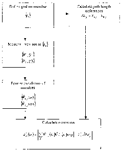
Figure 8a shows an embodiment having two sensors (102)
mounted on a member (100) to which a contact is applied at a
contact location (104). Figure 8 shows a method of calculating
the dispersion corrected correlation function to reveal the
difference in path length between the contact location (104)
and the sensors (102). The method comprises the following
steps:
(a) Measure two bending wave signals W1 (t) and Wz(t) ;
(b) Remove reflections from the measured signals and calculate
~'(t) and Wi (t) , a . g . by using the method set out in Figure 9 ;
(c) Calculate the Fourier transform of W'(t) and Walt) to
arrive at W (t~) and WZ(tv) and hence the intermediate function
31
CA 02450859 2003-12-16
WO 03/005292 PCT/GB02/03073
W (t~) W2 (w) ; where Wz (w) is the complex conjugate Fourier
transform.
(d) and (e) at the same time as performing steps (a) to (c) ,
the frequency' stretching operation f(c~)=vC~ is calculated
using the predetermined panel dispersion relation k = C~.
( f ) W (ev) and WZ (w) and f (ev) = vC~ are combined to arrive at
the dispersion corrected correlation function:
G(t)= ~~ ~~W Lf'(cv)~YVZ ~f'(~)~exp(ieot)d~ ; and
(g) the dispersion corrected correlation function is plotted
against time with a peak occurring at time t12 as shown in
Figure 8b;
(h) Oxs,2 is calculated from tl~; 0x12 is the path-length
difference between the path lengths x1 and x2 from the first
and second sensors to the contact.
(i) 1x12 is used to calculate the location of the contact.
Alternatively at step (e), the dispersion corrected
correlation function with phase correction ~1~ set out below
may be used. The calculation of X12 is explained in Figure 13.
G(t)= 2~, ~~T~i~(~~~a ~~~~~ ~ia~~~~~ eXP(ievt)dCr~
Figure 9 shows a method of removing reflections from an
impulse measurement where the impulse occurs at t=0. The
method comprises the following steps:
i) Measure a bending wave signal ~(t);
32
CA 02450859 2003-12-16
WO 03/005292 PCT/GB02/03073
ii) Transform the signal on the time axis by using U(z?= W(1/z);
iii) A low pass filter is applied, for example, U'(i) as shown
to remove all reflected signals. The °constant C from the
predetermined panel dispersion relation k = C~ is used to
define the width of the convolution function Di;
iv) The response may then be transformed back to linear units
of time, as W'(t)=U(l~t).
Figure 10 shows an alternative method for removing
reflections from an impulse measurement where the impulse
occurs at t=0. The method comprises the following steps:
i ) Measure a bending wave signal Wi (t) ;
ii) Estimate the distance x between each sensor and the
location of the contact;
iii) Use the estimate x and a predetermined dispersion
relation k=C~ to define an averaging window N (t, t' )
iv) Apply the averaging window N(t, t') to the bending wave
signal W (t) to remove the effect of reflections.
N(t,t') is an example of an averaging window with a
Gaussian shape. A rectangular window can be implemented to
give computational efficiency. Multiple applications of a
rectangular window may be desirable; a large number of
repeated applications of a rectangular window will produce a
similar result to N(t,t').
Figures lla and 11b show a contact sensitive device (80)
comprising a rectangular member (82) capable of supporting
33
CA 02450859 2003-12-16
WO 03/005292 PCT/GB02/03073
bending waves and four sensors (84) for measuring bending wave
vibration in the member. The sensors (84) are in the form of
piezoelectric vibration sensors and are mounted on the
underside of the member (82), one at each corner. A foam
mounting (86) is attached to the underside of the member and
extends substantially around the periphery of the member. The
foam mounting (86) has adhesive surfaces whereby the member
may be securely attached to any surface. The foam mounting may
reduce the reflections from the edge of the member.
Two sets of path length differences, Oxlz=xl-x2 and
x34=x3-x4 are calculated as described in Figure 8 ; xi is the
distance from each sensor to the contact. As shown in Figure
llb the hyperbolae (85) defined by the two path-length
differences are plotted and the location of the contact is the
intersection (87) of two hyperbolae.
Figure 12 is a schematic diagram illustrating the
implementation of a processing algorithm in the device of
Figure 11. The sensors (84) measure analogue bending wave
signals W1(t), W2(t) and W3(t) which are passed through an
amplifier and anti-aliasing (low-pass) filter (88). The
amplitude of the combined transfer function H(t) of the
amplifier and anti-aliasing filter is shown in Figure 12a. The
filtered signals are converted into digital signals by a
digitiser (90) and stored in a first-in-first-out buffer
having finite length. The buffer comprises two stores, a pre-
trigger and a post-trigger store (92,93) for signals measured
34
CA 02450859 2003-12-16
WO 03/005292 PCT/GB02/03073
before and after the detection process is triggered
respectively.
The central processor (94) determines information relating
to the location and profile of a contact of the member by the
following steps:
a) The central processor performs a threshold test which is
illustrated in Figure 12b. The measured bending wave
signal (96) is compared to a predetermined threshold value
(98). When the measured signal passes the threshold
value, the detection process is triggered.
b) An array of time-series digital input signals is
transferred from the buffer to the processor. The signals
include measurements taken before and after the detection
process is triggered so that a digital measure of the
entire waveform of the impulse from the contact is
reconstructed.
c) The processor shifts the waveform according to the
estimate of to so that to is set to zero.
d) The processor removes the effect of reflections from the
digitised signal as described above with the estimate of
to as zero and the estimate of x taken as the diagonal
length of the member.
e) The processor applies further processing, in particular
calculating the dispersion corrected correlation function
for each diagonally opposed pair of sensors and
calculating information relating to the contact.
CA 02450859 2003-12-16
WO 03/005292 PCT/GB02/03073
The further processing applied by the processor may also
comprise applying a pre-determined phase correction to the
dispersion corrected correlation function. This may be
calculated as shown in Figure 13.
a) Define a grid - fox example, for the embodiment shown in
Figures 11a and 11b which has a member (82) which four
sensors (84), this may be done by defining points (71) by
the vector ~r~~. In this example the grid has 8 rows and 7
columns so the grid is defined by a set of 56 vectors [r1,
ra ... rssl .
b) A user taps on the first point (71) in the grid defined by
r1 and the first and second bending wave signals f Wl,~ (t)
and ~W2,~(t)~ are measured by the first and second sensor of
each pair of sensors;
c) Step (b) is repeated until the user has tapped on each
point in the grid;
d) Calculate the Fourier transforms of the bending wave
signals;
e) Calculate the empirical phase correction:
~12~~~ ~~,j(~)~2J~~)exp~ ak(w)~j
j
where Ox.~ is the difference between the path lengths, xl,~ & x~,~
from the first and second sensors to the contact. The path
lengths are known from the grid coordinates.
Figure 14 shows a contact sensitive device (70)
comprising a member (72) capable of supporting bending waves
36
CA 02450859 2003-12-16
WO 03/005292 PCT/GB02/03073
and three sensors (64) mounted on the member for measuring
bending wave vibration in the member. A surface of the member
(72) comprises a raised pattern (66) which is a periodic
pattern of raised crossed lines. A stylus (78) is drawn across
the surface along a path (74) and as it crosses a line of the
pattern it generates bending waves (76) in the member.
Figure 15 shows an adaptive noise canceller for example
as described in "Widrow et al Adaptive Noise Cancelling:
Principles and Applications, Proceedings of the IEEE, Vol 63
No 12 pp 1692 (1975)". The adaptive noise canceller comprises
an adaptive filter (40) which takes the initial audio signal
as the reference input. The canceller may be used to remove
the contribution of the audio signal from the output of a
vibration sensor before any further processing occurs. The
adaptive filter shown is one example of an adaptive filter
that can be applied to this task.
Figure 16a shows a contact sensitive device which also
operates as a loudspeaker. Figure 16b shows a method for
partitioning the audio signal and measured signal into two
distinct frequency bands so that the contribution of the audio
signal to the processed measured signal is suppressed. The
device comprises a member (106) in which bending waves are
generated by an emitting transducer or actuator (108) and the
contact. The emitting transducer applies an audio signal to
the member (106) to generate an acoustic output. Before being
applied to the member, the audio signal is filtered by a low
37
CA 02450859 2003-12-16
WO 03/005292 PCT/GB02/03073
pass filter (112) which, as shown in Figure 16b, removes the
audio signal above a threshold frequency fo.
As shown in Figure 16b, the contact generates a signal
which has a power output which is substantially constant over
a large frequency band. The signal from the contact and the
audio signal sum to give a combined signal which is passed
through a high pass filter (114) to remove the signal above
the threshold frequency fo. The filtered signal is then
passed to a digitiser (116) and onto a processor (118).
Figure 17a shows an embodiment having a single sensor
(120) mounted on a member (100) to which a contact is applied
at a contact location (104). Bending waves are reflected from
the edge of the member and create an image of a virtual source
which is at location (122). Figure 17 shows a method of
calculating the dispersion corrected auto-correlation function
to reveal the contact location (104). The method comprises
the following steps:
(a) Measure one bending wave signal Wilt) ;
(b) Calculate the Fourier transform of T~Y'(t) to arrive at
2 0 YYl (t.~) ;
(c) at the same time as performing steps (a) and (b), the
frequency stretching operation f~tv)= vC~ is calculated using
the predetermined panel dispersion relation k = ~'~.
( d) W, (~) and f (w) = teC~ are combined to arrive at the
dispersion corrected auto-correlation function:
38
CA 02450859 2003-12-16
WO 03/005292 PCT/GB02/03073
G(t)=~~ ~~W ~f'pv~~Wz ~,f'~tv)~exp(iwt)dw ; and
(g) the dispersion corrected correlation function is plotted
against time with peaks occurring at time tli and -t11 as shown
in Figure 17b;
(h) 0x11 is calculated from t11; Oxla is the path-length
difference between the path lengths x,, and xl~ from the first
and second sensors to the contact.
(i) dxl2 is used to calculate the location of the contact.
Figure 18 shows the adaptive filter of Figure 15 may also
be used to calculate the location of the contact from a device
comprising two sensors. In general, adaptive filters contain a
finite-impulse-response (FIR) filter. A FIR filter is
equivalent to a convolution operation, with some convolution
function ~ (t) .
The signals Wl (t) measured by the first sensor are sent
to the adaptive filter (40) and the signals W2 (t) measured by
the second sensor are sent to a delay unit (41). The delay
unit delays the signals from the second sensor, preferably by
the maximum expected width of the convolution function. The
delayed signals are then sent to the primary input of the
adaptive filter. The adaptive filter continually updates the
convolution function so that an estimate, WZ(t), of the primary
signal input, W2(t), may be obtained from the reference input,
W1(t). The convolution operation is defined as follows:
39
CA 02450859 2003-12-16
WO 03/005292 PCT/GB02/03073
W2 (t) _ ~~W(t')~(t-t')dt' .
The location of the contact is calculated in the
processor by the following steps:
a) Extract the FIR convolution function from the internal
memory of the adaptive filter.
b) Calculate the Fourier transform of the FIR convolution
function.
c) Apply the frequency stretching operation f(w)= vC'~;
d) Calculate the inverse Fourier transform to arrive at F(t).
F(t) is a phase equivalent of the dispersion correction
correlation function G(t) and thus the Fourier~ transforms of
G(t) and F(t) have equal phase but not necessarily the same
amplitude. Accordingly, the location of any peaks in the time
domain for F(t) and G(t) are the same and thus the location of
the contact may be calculated from the peak of F(t) as
described above for G (t) .