Note: Descriptions are shown in the official language in which they were submitted.
CA 02451488 2003-11-28
ULTRAVIOLET LAMP ASSEMBLY
FIELD OF THE INVENTION
[ 0001] The present invention generally relates to an ultraviolet lamp
assembly for killing
germs or bacteria in air ventilation systems. Specifically, the present
invention relates to an
ultraviolet lamp including a quartz sleeve having a vented open end which
results in increased or
improved germicidal and bactericidal effect in systems and apparatus using
ultraviolet lamps for
purification or cleaning of air.
BACKGROUND OF THE INVENTION
[ 0002] The use of certain wave lengths of ultraviolet ("UV") light or
radiation for its
purification, germicidal and bactericidal effect is well known. UV light is
commonly used to
control the growth of and kill impurities in septic, water and air systems.
For example, UV light
or UV lamps axe commonly used in heating, ventilation, and air conditioning
("AC" or "HVAC")
systems for purification or air cleaning purposes. UV lamps are typically
installed or mounted in
the air ducts of AC systems in such a manxler that the UV light emitted by the
lamp floods the
interior of the air duct. Air flowing through that duct will be irradiated
with UV radiation which
will have a germicidal or bactericidal affect on the moving air thereby
reducing the impurities in
the air flow.
[ 0003] A drawback of existing UV lamps in exiting UV lamp assemblies is that
the UV
lamps experience diminished UV radiation output intensity o~aer time which
results in reduced
germicidal and bactericidal affect of the UV lamp cleaning device. Output from
such UV lamps
typically reaches its maximum rated output intensity after the first few
minutes of operation,
after an initial heat up period of the UV lamp. The UV lamp output then
typically decreases over
time to a generally steady lamp intensity output as the lamp continues to
operate. The steady
21217415.1
CA 02451488 2003-11-28
state output is about 20% less that the maximum output obtained during the
first few minutes of
UV lamp operation. The drop in UV lamp output intensity is typically due to
the inconsistent
and variable temperature around the UV lamp that does not allow proper and
uniform UV lamp
cooling. The diminished UV lamp output is even more pronounced when air or
water is
circulated around the lamp which causes a higher rate of cooling as is well
know to those of skill
in the art.
[ 0004] Moreover, inconsistent and variable air temperatures present around a
standard
UV lamp result in a cooling affect that does not allow proper and uniform UV
lamp cooling. In
the long term, this cooling effect can adversely affect the UV lamp's
germicidal or bactericidal
effect by causing the inside of the lamp to blacken or darken which in turn
causes or results in a
reduced UV lamp output intensity level.
[ 0005] In other typical UV lamp configuration, the ITV lamp is mounted inside
a quartz
tube as an attempt to counteract known lamp-cooling issues or problems.
However, such a
configuration, when operated in still air, results in a larger drop in UV lamp
intensity output than
a standalone UV lamp. Output of a UV lamp covered by a quartz tube typically
reaches its
maximum rated output intensity after a few minutes of operation after the
initial heat-up or
warm-up period. Again, the UV lamp output will typically decrease to a
generally steady lamp
intensity output as the lamp continues to operate. In this configuration, the
steady state output is
about ~S% less that the maximum output obtained during the first few minutes
of UV lamp
operation. Thus, the quartz outer tube results in a greater loss of UV lamp
output intensity.
[ 0006] There is thus a need for an improved ultraviolet UV lamp assembly
having
improved UV lamp temperature characteristics for improved 1;JV radiation
intensity output for
2
21217415.1
CA 02451488 2003-11-28
improved germicidal and bactericidal affect in purification, sterilization,
cleaning or airflow
systems.
SUMMARY OF THE INVENTION
[ 0007] The present invention provides a method and apparatus for an improved
ultraviolet lamp assembly using an ultraviolet (UV) lamp with a vented quartz
sleeve or tube
having improved UV lamp temperature and cooling characteristics resulting in
improved UV
lamp intensity output for increased germicidal and bactericidal effect. The UV
lamp assembly of
the present invention can be used in systems and applications intended to
purify, sterilize, clean
and sanitize a medium, object or device. Further, the vented sleeve or tube is
preferably a vented
open end tube though other configurations may be used depending on a
particular use application
of the UV lamp assembly.
[ 0008] In one embodiment, the ultraviolet lamp assembly comprises a UV lamp
housed
in a vented open end quartz sleeve or tube in a portable air conditioning (AC)
or heating unit.
The quartz sleeve comprises a distal open end and a proximal open end. The UV
lamp can be
inserted into either end and secured to the tube, and the sleeve or tube is
then secured to the AC
or heating unit. 'The proximal open end of the quartz sleeve comprises a
plurality of venting slots
or ports that allow the air to travel into and out of the area or space
between the UV lamp and the
sleeve wall. The movement of air is preferably initiated by a fan or air
displacer in the unit.
Operation of the unit's fan results in air flow into the quartz sleeve at a
proximal sleeve base end
and out through the distal open end of the quartz tube. Air can also be drawn
through the tube
without operation of the fan by creating a "chimney" effect in tile quartz
tube from the heating of
the air in the tube.
3
21217415.1
CA 02451488 2003-11-28
[ 0009] It is an object of the present invention to provide an ultraviolet
lamp assembly that
can be used in an AC or HVAC system for purification and cleaning of air
flowing in the AC or
HVAC system air ducts.
[ 0010] It is an object of the present invention to provide a UV lamp assembly
with a
vented quartz sleeve to provide improved and more consistent UV radiation
intensity output.
[ 0011] It is an object of the present invention to provide a UV lamp assembly
with a
vented quartz sleeve with an open distal end to provide unproved and more
consistent UV
radiation intensity output.
[ 0012] It is an object of the present invention to increase UV lamp life by
producing
more consistent and stable UV lamp temperature.
[ 0013] It is an object of the present invention to provide a UV lamp assembly
with a
vented quartz sleeve where the UV radiation intensity output is substantially
uniform and
constant when an associated AC fan is operating.
[ 0014] It is an object of the present invention to provide a shield or panel
for the UV
lamp assembly to improve and maintain the UV radiation intensity output of the
UV lamp and
where the shield or panel can be curved and extend to about 120 degrees.
[ 0015] It is an object of the present invention to provide a UV lamp assembly
having an
effective germicidal and bactericidal affect in a wavelength of about 254 nm.
[ 0016] It is an object of the present invention to providLe a UV lamp
assembly where the
air around a UV lamp can be maintained in the range of 80°F 'to
100°F for improved germicidal
and bactericidal affect in an air purification system.
4
21217415.1
CA 02451488 2003-11-28
[ 0017] It is an object of the present invention to provide an ultraviolet
lamp assembly that
can be used to purify air in an airflow system such as an air conditioning
system in a home, hotel
or building.
[ 0018] It is an object of the present invention to provide an ultraviolet
lamp assembly that
can be used to purify air in an airflow system such as a portable or
standalone air conditioning
unit.
[ 0019] The following drawings and description set forth additional advantages
and
benefits of the invention. More advantages and benefits will be obvious from
the description and
may be learned by practice of the invention.
BRIEF DESCRIPTION OF THE DRAWINGS
[ 0020] The present invention may be better understood. when read in
connection with the
accompanying drawings, of which:
[ 4021] Figure 1 illustrates a novel ultraviolet lamp assembly positioned on a
portion of a
housing of a portable air conditioning unit in accordance with an embodiment
of the present
invention;
[ 0022] Figure 2 illustrates an isometric view of the ultraviolet lamp
assembly of Figure 2
on the housing of a portable air conditioning unit;
[ 0023] Figure 3A illustrates a top view of the housing and ultraviolet lamp
assembly of
Figures 2 and 3;
[ 0024] Figure 3B illustrates a rear view of the housing and the ultraviolet
lamp assembly
of Figures 1 and 2;
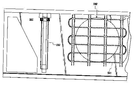
[ 0025] Figure 4 illustrates an ultraviolet lamp assembly positioned on a
housing of a
portable air conditioning unit in accordance with another embodiment of the
present invention;
21217415.1
CA 02451488 2003-11-28 -
[ 0026] Figure 5 illustrates a sleeve base of the ultraviolet lamp assembly of
Figure 4
showing a plurality of venting slots according to an ernbodime;nt of the
present invention;
[ 0027] Figure 6 illustrates a sleeve distal open end and a shield of the
ultraviolet lamp
assembly of Figure 4;
[ 0028] Figure 7 illustrates an air conditioning unit where the ultraviolet
lamp assembly of
Figures l and 4 could be used;
[ 0029] Figure 8 illustrates the air conditioning unit with the ultraviolet
lamp assembly of
Figure 4 mounted therein according to an embodiment of the present invention;
[ 0030] Figure 9 illustrates the air conditioning unit of Figure 8 with a fan
guard
positioned above the ultraviolet lamp assembly of Figure 4; and
[ 0031 ] Figure 10 illustrates a circulation fan that could be used with the
air conditioning
unit of Figure 7 to circulate air in the ultraviolet lamp assembly of Figure
4.
DETAILED DESCRIPTION
[ 0032] Figure 1 shows an embodiment of a novel ultraviolet lamp assembly 200
positioned and secured to a portion of a housing 201 of a portable air
conditioning unit (shown in
Figure 7) in accordance with the present invention. The UV lamp assembly 200
preferably
comprises a UV lamp 205 and a quartz tube or sleeve 230 with a proximal base
end 203 having a
plurality of venting ports or slots 237 and an open distal end 235. The
ultraviolet (UV) lamp 205
preferably has a bandwidth of about 240nm to 360nm for best germicidal and
bactericidal affect.
Other bandwidths outside this range or a specific wavelength within the range
may be used for
specific desired applications. In the preferred embodiment, the UV lamp 205 is
an ozone free
UV lamp which is operatively housed in the elongated sleeve or tube 230.
However, other types
of lamps and lamp configurations may be used and the assernhly may have one or
more UV
6
21217415.1
CA 02451488 2003-11-28
lamps 205. The quartz sleeve 230 will preferably have complimentary physical
configurations to
accommodate and house one or more UV lamps 205 having other shapes and sizes.
The
ultraviolet lamp assembly 200 can also be used in other cleaning or
purification systems that are
not portable and have extensive air ducts.
[ 0033] The sleeve 230 is preferably an elongated hollow tube with a proximal
end 223
(also shown in Figure 5). The sleeve or tube 230 is preferably comprised of a
quartz material,
however other suitable UV transparent materials may used to make up the sleeve
230. The
proximal end 223 preferably has a base 203 connected to the tube 230 and is
configured such
that the UV lamp 205 can be inserted into the quartz sleeve 230 and secured to
the base 203.
Further, the base 203 preferably comprises a plurality of venting orifices,
air vents, slots or ports
237. In the embodiment shown, there are four venting slots 237 (shown in
Figure 5), however
those of skill in the art will readily recognize that the number of venting
orifices 237 may be
more or less depending on the particular applicatian where the UV lamp
assembly 200 is to be
used. The plurality of venting orifices or ports 237 in the base 203 and the
distal open end 235
enable or allow air to enter and/or exit the quartz sleeve 230, ii.e., to
travel into or out of a space
207 that is formed between the UV lamp 205 and the quartz sleeve 230.
[ 0034] The UV lamp 205 is preferably positioned and secured to the sleeve 230
at the
proximal open end 223 of the sleeve 230 (also shown in Figure 5). When the UV
lamp 205 is
operatively positioned in the sleeve 230 there is a space 207 between the UV
lamp's 205 outer or
exterior surface and the interior surface or wall of the sleeve 230 is formed
and created. The
venting slots 237 in the sleeve base 203 and the distal open end 235 form an
airflow pathway for
air to enter and exit the quartz sleeve 230 and to move in the ai:r space 207
between the UV lamp
205 and the quartz sleeve 230. This will allow circulation of air or air flow
through the interior
7
21217415.1
CA 02451488 2003-11-28
r ,
of the quartz sleeve 220 from venting slots 237 to distal end 235 or in the
opposite direction from
distal open end 235 to venting slots 237. The flow of air or other selected
medium allows the
appropriate, consistent and uniform cooling of the UV lamp during operation of
the lamp. In this
manner, the UV lamp output intensity can be maintained at a higher level for a
longer period of
time and thus increase the germicidal and bactericidal effect of the UV lamp.
[ 0035] Figure 2 shows an isometric view of a preferred embodiment of the
ultraviolet
lamp assembly 200 shown in Figure 2 positioned on a panel or housing 201 which
can be
mounted in the interior of a portable air conditioning unit 800 (shown in
Figures 7 and 8). The
AC unit 800 can be a typical portable appliance or device that may perform the
functions of
cooling and/or heating air. Such a device may be located in a window or in a
wall for
circulation of ambient room air. Figures 3A and 3B shown top and rear views of
the housing
201 and ultraviolet lamp assembly 200 of Figure 2. As shown, the UV lamp
assembly 200 is
preferably secured to a top portion 301 of the housing 201 at the base end 203
such that the UV
lamp 205 and the quartz sleeve 230 extend vertically downward from the top 301
and in front of
the housing 201. (also shown in Figure 4)
[ 0036] Figure 4 further shows that the UV lamp assembly 200 is preferably
mounted on
the front side of the housing 301. 'Those of skill in the art v~nll readily
recognize that the UV
lamp assembly can be mounted in other desired or appropriate locations of the
housing 301 or
portable AC unit 800.
[ 0037] In an alternate embodiment, the UV lamp assembly 200 further comprises
a shield
or panel 530 that is preferably configured to extend from approximately the
base 203 to the distal
end 235 and is curved lengthwise to cover approximately half of the quartz
sleeve 230 (shown in
Figures 4 and 6). The shield or panel can be curved from about 120 to 180
degrees. Further, the
21217415.1
8
_. ...._. .... _..r.",." ,m:,. "~;,"~e.,.e;"~T~r ~~,~.~.,"~.........."......_
._.._........_ .~.._ ." ..".,...._..._. "."._ _... ..
CA 02451488 2003-11-28
w ,
shield is preferably positioned between the housing wall 501 and the quartz
sleeve 230. The
shield or panel 530 can deflect or direct the UV radiation in a desired
direction. The shield or
panel can also serve to protect the housing wall 501 which may contain plastic
parts, from
degradation to the generated UV radiation. Those of skill in the art will
readily recognize that
whether or not a shield or panel 530 is used will depend on the particular
application of where
the UV lamp assembly 200 is to be used and components or objects in the
vicinity of the UV
lamp assembly 200 UV radiation, such as the housing wall SOI..
[ 0038] Figure 5 shows in more detail the proximal end 223 of the quartz
sleeve 230 and
particularly the plurality of venting slots or ports 237 in the base 203 . It
also show how the UV
lamp 205 is mounted to the base 203 in this embodiment. Figure 6 shows in more
detail the
distal open end 235 of the quart sleeve 230, as well as a bottom portion of
the curved shield or
panel 530 that is used in some embodiments to redirect UV radiation and/or to
protect
surrounding material and components from UV radiation. Together, the venting
ports or slots
237 and the distal open end 235 provide or define an airflow path to enable or
allow air to enter
and exit the quartz sleeve 230 and to travel in the space 207 between the UV
lamp 205 and the
quartz sleeve 230.
[ 0039] Figures 7-10, illustrate an air conditioning unit 800 where
embodiments of the
ultraviolet lamp assembly 200 may be mounted and used, preferably in the
interior of an AC unit
800. The AC unit 800 may be a portable appliance and it can be a device that
performs the
functions of cooling and/or heating air. Such a device may be located in a
room, window or in a
wall for circulation of ambient room air, or could be paxt of a larger air
conditioning system.
Figure 7 further shows the preferred position of the UV lamp assembly 200 in
the AC unit 800 in
this embodiment. Figure 8 shows that, in the AC unit 800 of Figure 8, the UV
lamp assembly
9
21217415.1
CA 02451488 2003-11-28
200 of Figures 1-4 is preferably mounted inside the AC unit 800 and between
the AC coils 906
and the unit circulation fan 1040 (shown in Figure 10). Figure; 9 further
shows that a fan guard is
preferably mounted above the UV lamp assembly 200 and housing 201. This can be
for safety
purposes and/or to keep debris out the area above the UV lamp assembly 200.
[ 0040] In operation, the UV lamp assembly 200 is preferably mounted or
positioned in a
housing 201 (Figures l, 2, 3A, 3B and 4) in the interior of a portable air
conditioning unit 800
(Figure 7). The UV lamp assembly 200 is preferably secured to the top portion
301 (shown in
Figures 2, 3A and 8) and positioned in front of the housing 301 (shown in
Figure 4). The
housing 201 with the attached UV lamp assembly 200 is positioned inside the AC
unit 800
(shown in Figures 8 and 9) and adjacent to or in front of the AC coils 906
(shown in Figures 8 &
9). Cooperatively positioned adjacent to the rear of the housing 201 is a
circulation fan 1040
(shown in Figure 10) that, when in operation, will pull ambient air from a
room or other
designated air source. When the circulation fan 1040 is operating, the ambient
air is pulled from
the area outside the front grill or cover 840 of the AC unit 80C1 and into the
AC unit. The intake
ambient air passes the UV lamp assembly 200, the AC coils !a06 and a heater
strip 541 that, in
this embodiment, is mounted to the front of the housing 201. The intake
ambient air then travels
or flows through a fan intake orifice 540 (shown in Figures 2, 3B and 4). Once
the intake
ambient air passes the fan intake orifice 540, the air is forced o~r routed
upward toward the top of
the AC unit 800 where the air exits the AC unit 800 through exit vents 850
(Figure 7).
[ 0041 J The air that exits the AC unit 800 via the exit vents 850 will either
be hotter or
colder as compared to the air entering the AC unit 800 via the front AC unit
cover 840 depending
on the unit's 800 mode of operation. If the AC unit 800 was in heater mode,
then the air exiting
the AC unit 800 will be heated by the heater strip 541 as the air passes into
the fan intake orifice
21217415.1
CA 02451488 2003-11-28
540. If the AC unit 800 was in cooling mode, then the air exiting the AC unit
will be cooled by
the AC coils 906 as the air passes toward the fan intake orifice 540.
[ 0042] During operation of the circulation fan 1040, a portion of the air the
being routed
or expelled out through the AC exits vents 850 may be diverted through the UV
lamp assembly
200. During operation of the intake circulation fan 1040, the front area of
the housing 201 is at a
negative pressure relative to the top 301 rear part of the housing 201 where
the air that was
sucked in by the circulation fan is being expelled. There is thus a negative
pressure at the distal
open end 235 of the sleeve 230. At the same time, there is a higher positive
pressure at the
proximal base 203, which has the venting slots 237, positioned at the top 301
of the housing 201.
As noted previously, the proximal base venting slots 237 and the distal open
end 235 of the
sleeve 230 form a path or conduit for airflow. And, since the area above the
proximal base
venting slots 237 is at a higher or positive pressure and the sleeve distal
open end 235 is at a
negative pressure relative to venting slots, a portion of the air exiting the
AC unit may be sucked,
funneled or forced to travel into the sleeve 230 due to the pressure
difference. The air will travel
in the space 207 between the UV lamp 205 and the sleeve 230 from the venting
slots 237
downward and out at the distal open end 235 into the area in front of the
housing 201. The air
will then join air that is being pulled through the fan intake 540 and
circulate as just described.
[ 0043] The air traveling through the sleeve 230 as a result of the pressure
differential
created by the intake circulation fan 1040, as just described, preferably
produces a cooling air
flow in the UV lamp assembly 200 inside the quartz sleeve 230 that enables the
UV lamp 205
maintain a consistent temperature and/or to control the temperature in the
space 207 between the
UV lamp 205 and the sleeve 230. This will allow the UV lamp intensity output
to be maintained
near its maximum output. The improved UV intensity output will allow the UV
lamp assembly
11
21217415.1
CA 02451488 2003-11-28
200 to provide an improved germicidal and bactericidal affect. This will
enable a system that
uses the UV lamp assembly to better purify the ambient air and, as a result, a
portable air
conditioning system using such a UV assembly 200 will able; to provide cleaner
air. For a UV
lamp operating at a wavelength of 254 nm, the temperature around the lamp is
preferably
maintained in the range of about range of 80°F to 100°F for
consistent and improved germicidal
and bactericidal affect on the air in the AC unit 800. Those of skill in the
art will readily
recognize that the preferred temperature will depend on the rated output
intensity and length of
the UV lamp 205 uses in the UV lamp assembly 200. In one embodiment, the
preferred
temperature is 90°F for a UV lamp 205 operating at a 2 54 nm wavelength
for optimum
germicidal affect on the ambient air in the AC unit 800.
[ 0044] The invention has been described and illustrated with respect to
certain preferred
embodiments by way of example only. Those skilled in that art will recognize
that the preferred
embodiments may be altered or amended without departing from the true spirit
and scope of the
invention. Therefore, the invention is not limited to the specific details,
representative devices,
and illustrated examples in this description. The present invention is limited
only by the
following claims and equivalents.
12
21217415.1