Language selection

Search

Patent 2451564 Summary

Third-party information liability

Some of the information on this Web page has been provided by external sources. The Government of Canada is not responsible for the accuracy, reliability or currency of the information supplied by external sources. Users wishing to rely upon this information should consult directly with the source of the information. Content provided by external sources is not subject to official languages, privacy and accessibility requirements.

Claims and Abstract availability

Any discrepancies in the text and image of the Claims and Abstract are due to differing posting times. Text of the Claims and Abstract are posted:

  • At the time the application is open to public inspection;
  • At the time of issue of the patent (grant).
(12) Patent Application: (11) CA 2451564
(54) English Title: THE PIT BADGER
(54) French Title: DISPOSITIF POUR BENNE CHARGEUSE « THE PIT BADGER »
Status: Deemed Abandoned and Beyond the Period of Reinstatement - Pending Response to Notice of Disregarded Communication
Bibliographic Data
(51) International Patent Classification (IPC):
  • A01F 25/20 (2006.01)
  • A01D 87/00 (2006.01)
  • A01D 90/02 (2006.01)
  • A01K 5/00 (2006.01)
(72) Inventors :
  • STANG, GORDON JACOB (Canada)
(73) Owners :
  • GORDON JACOB STANG
(71) Applicants :
  • GORDON JACOB STANG (Canada)
(74) Agent:
(74) Associate agent:
(45) Issued:
(22) Filed Date: 2003-12-23
(41) Open to Public Inspection: 2005-06-23
Examination requested: 2004-02-09
Availability of licence: N/A
Dedicated to the Public: N/A
(25) Language of filing: English

Patent Cooperation Treaty (PCT): No

(30) Application Priority Data: None

Abstracts

English Abstract


< IMG >

This attachment mounts on a bucket of a tractor. It is used for digging and
transporting
feed out of a feed pit and into a wagon. It saves operators, time, fuel and
equipment.
The front auger is mounted into the bucket of the loader. The auger moves the
feed
along to where paddles are mounted and sweep the silage through a back hole
cut in
the bucket and along a conveyer belt system which consists of 2 conveyor
assemblies.
The first assembly is movable so it corresponds with the movement of the front-
end-loader.
The second conveyor assembly is mounted solidly on the tractor and extends
past
the back of the tractor to the feed wagon.
The assemblies are attached with a mounting bracket that enables the first
assembly
system to slide forward and backward on the second system as the front end
loader
moves up and down.


Claims

Note: Claims are shown in the official language in which they were submitted.

Claims
The embodiments of the invention in which an exclusive property or
privilege is claimed is defined as follows:
A
1. This attachment is driven hydraulically to move feed from the feed pile
to the feed wagon and is bolted directly onto the tractor and farmhand.
The feed is moved from the pit by an auger and paddle system, goes
through an opening the in the back of the bucket and follows a conveyor
belt system until it reaches the feed wagon.
2. A tool as defined in claim 1 , it consists of an auger system and 2
conveyor assembly attachments that carry out the movement of feed.
The first conveyor system moves with the farmhand and the second on is
a solid attachment to the tractor
3. An attachment as defined in claim 1 and 2, as, ail attachments are
detachable when not in use.
4. An attachment as defined in claim 1, 2 and 3 that clearly eliminates the
use of two tractors and enables better time management, better fuel
economy and therefore environmentalley friendly.

Description

Note: Descriptions are shown in the official language in which they were submitted.


CA 02451564 2003-12-23
1
Description of Drawings
The Pit Badger
The Pit Badger is a method to use one tractor to load feed for livestock.
This attachment mounts on a front-end loader of a tractor. It is used for
digging silage
out of a silage pit and transporting it into a feed wagon. The front auger is
mounted into
the bucket of the front-end-loader by side mounted brackets. The front auger
grabs the
silage and moves it from the left to the right hand-side of the bucket. There
are paddles
on the right-hand-side of the auger that force the silage backward through a
hole cut in
the back of the bucket. The silage moves along the conveyers into the wagon.
The
front auger is run by a hydraulic motor that is mounted on the left-hand-side
of the back
of the bucket and is chain and sprocket driven. The conveyor belts are run by
two
hydraulic motors as well.
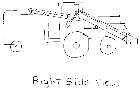
Figure 1 shows the left-hand side view of the whole unit attached to a
tractor. You can
see the conveyor systems and design of how the attachment works
Figure 2 is the top view of the farmhand and figure 3 is the front view of the
attachment
in the bucket. # 1 is a hydraulic motor that is attached to the back of the
bucket. It runs
a chain that drives a sprocket ( # 2) attached to the shaft of the auger. The
flighting
(#4) is attached to the shaft {#3) . At the end of the shaft are 2 or 4 feeder
paddles ( # 5)
which transport the silage through a hole { #6) in the back of the bucket to
the conveyor
assemblies.
Conveyer Belt Assembly
Figure # 4
The conveyor assembly is attached to the back of the bucket with pins. ( # 7)
The feed
then navels along a conveyor belt which is encased in a tin enclosure like box
with an

CA 02451564 2003-12-23
2
open top . The sides are 1 foot deep above the conveyor to prevent the silage
from
spilling them. The conveyor belts are run by hydraulic motors attached to
shaft at # 8 on
the Left-hand-side. The first conveyor belt assembly is mounted higher on the
tractor
than the second belt assembly to allow for up-an-down movement of the farm
hand.
This also allows silage to fall onto the second conveyor belt assembly.
Figure # 5 The second conveyor belt is solidly fixed to the tractor. 'this
belt system
caries the feed to the wagon. It allows the feed to fall off the end of the
conveyor belt
directly into the wagon. This conveyor belt system is also run by a hydraulic
motor that
is positioned on the left-hand-side of the assembly ( # 9). Bath motors will
be hooked in
series so that they are driven at the same speed.
Figure # 6
Due to the fact that the first conveyor assembly must move with the farm hand
movement, a special bracket must be designed to adapt to this situation. The
top bracket
{ # 18) is bolted solid to the first section of the conveyor assembly. # 12
bolt is bolted
to # I O and # 11 bolted to # 13 to hold this bracket assembly solid on the
underside of
first conveyor assembly. The bottom bracket # 14 sits on topside of 2nd
portion of
conveyor assembly. This slides in the track { # 16) on roller bearing marked #
19 and #
17 is the track for roller bearing # 20. These tracks are positioned on the
left and right-
hand-side of the 2nd portion of assembly conveyor. # 18 bracket sides into #
14 bracket to
join together and is secured with a washer and a hairpin to created stability.
This
enables the first conveyor assembly to run smoothly back and forth as the farm
hand is
raised and lowered.

Representative Drawing
A single figure which represents the drawing illustrating the invention.
Administrative Status

2024-08-01:As part of the Next Generation Patents (NGP) transition, the Canadian Patents Database (CPD) now contains a more detailed Event History, which replicates the Event Log of our new back-office solution.

Please note that "Inactive:" events refers to events no longer in use in our new back-office solution.

For a clearer understanding of the status of the application/patent presented on this page, the site Disclaimer , as well as the definitions for Patent , Event History , Maintenance Fee  and Payment History  should be consulted.

Event History

Description Date
Inactive: MF/reinstatement fee unallocated - Log 25 deleted 2006-09-20
Inactive: Office letter 2006-09-20
Application Not Reinstated by Deadline 2006-07-10
Inactive: Dead - No reply to s.30(2) Rules requisition 2006-07-10
Deemed Abandoned - Failure to Respond to Maintenance Fee Notice 2005-12-23
Inactive: Abandoned - No reply to s.30(2) Rules requisition 2005-07-11
Application Published (Open to Public Inspection) 2005-06-23
Inactive: Cover page published 2005-06-22
Inactive: S.30(2) Rules - Examiner requisition 2005-01-10
Letter Sent 2004-02-17
Request for Examination Requirements Determined Compliant 2004-02-09
Request for Examination Received 2004-02-09
All Requirements for Examination Determined Compliant 2004-02-09
Inactive: First IPC assigned 2004-02-04
Inactive: IPC assigned 2004-02-04
Letter Sent 2004-01-21
Inactive: Filing certificate - No RFE (English) 2004-01-20
Filing Requirements Determined Compliant 2004-01-20
Application Received - Regular National 2004-01-20

Abandonment History

Abandonment Date Reason Reinstatement Date
2005-12-23

Fee History

Fee Type Anniversary Year Due Date Paid Date
Application fee - small 2003-12-23
Request for examination - small 2004-02-09
Owners on Record

Note: Records showing the ownership history in alphabetical order.

Current Owners on Record
GORDON JACOB STANG
Past Owners on Record
None
Past Owners that do not appear in the "Owners on Record" listing will appear in other documentation within the application.
Documents

To view selected files, please enter reCAPTCHA code :


To view images, click a link in the Document Description column. To download the documents, select one or more checkboxes in the first column and then click the "Download Selected in PDF format (Zip Archive)" or the "Download Selected as Single PDF" button.

List of published and non-published patent-specific documents on the CPD .

If you have any difficulty accessing content, you can call the Client Service Centre at 1-866-997-1936 or send them an e-mail at CIPO Client Service Centre.


Document
Description 
Date
(yyyy-mm-dd) 
Number of pages   Size of Image (KB) 
Description 2003-12-23 2 102
Abstract 2003-12-23 2 63
Drawings 2003-12-23 6 125
Claims 2003-12-23 1 38
Representative drawing 2004-02-05 1 14
Cover Page 2005-06-10 1 44
Acknowledgement of Request for Examination 2004-02-17 1 174
Filing Certificate (English) 2004-01-20 1 160
Notice: Maintenance Fee Reminder 2005-09-26 1 119
Courtesy - Abandonment Letter (R30(2)) 2005-09-19 1 166
Courtesy - Abandonment Letter (Maintenance Fee) 2006-02-20 1 174
Second Notice: Maintenance Fee Reminder 2006-06-27 1 117
Correspondence 2004-01-20 1 15
Correspondence 2006-09-20 1 12
Fees 2006-08-23 1 56