Note: Descriptions are shown in the official language in which they were submitted.
CA 02451710 2003-12-31
METHOD AND APPARATUS FOR COUPLING WALL PANELS OF A BUILDING
The present invention relates to a method and apparatus for coupling wall
panels
of a building or other structure, such as a pre-cast concrete or brick
facades. More
s particularly, the inueation relates to coupling the panels to one another so
that the panels
are permitted to move relative to one another during an earthquake while
remaining
coupled together.
Earthqua~sea will often loosen or damage decorative or structural wall panels,
such
as pre-cast concrete or brick facades, In response to larger earthquakes, the
panels rnay
1 o become detached from the structure and fall to the grDUnd, potentially
causing injury,
property damage and even death. Other natural or man-made forces may also pose
threats
to the structural integrity of building panels.
Fukumato et al., U.S. Patent No. 5,163,25b, proposes an elasto-plasxic damper
to
couple non-structural partition walls to a building so that the coupling is
resistant to
15 earthquakes and high winds. ?he damper comprises a cylindrical shaft with
st constricted
waist portion that elastically and plastically defvtma in response to forces
in a plane
perpendicular to the longitudinal axis of the waist portion. A problem with
this approaoh
is that ii provides for lirsxit~d arrsounts of el~stie and plastic d
2fOrtnatl0n arid, therefore,
limited relative motion between the partition wail and building. This is
because rr~ete!
z o materials, the strength of which would be necessary to support the weight
of heavy
CA 02451710 2003-12-31
partition walls, will not elastically or plastically deform large amounts
before breaking
even where the materials arc annealed. Limiting the relative motion of the
partition wall
and building limits the amount of energy that can be dissipated.
Frobosilo et al., U.S. Patent No. 5,846,018, pcogoses a sea~mic slide clip
deflection
assembly including a Plato member for attachment to a frame of a building, an
angle clip
member having a 90 degree bend and a base slide plate member in which the
angle clip
member is horizontally siidingly received. The angle member includes a
vertically oriented
slat through which extends a head rivet and spring washer functioning as
slidable friction
means to siidingly secure the angle member to the plate member while
eliminating joint
play, The approach has the serious drawback of permitting relative horizontal
displacement of the pans coupled together along g single axis.
Accordingly, there is a need for a novel and improved method and apparatus far
coupling wall panels of a building or other structure that provides for
relatively large
movements of the panels with respect to one another during an earthquake along
two
~.5 orthogonal axes.
The method and apparatus for coupling wall panels of a building of the present
invetitivn solves th~ aforementioned problems and meets the aforementioned
needs by
providing a coupling assembly including a first coupling member depending from
a face of
z o one of the panels at a point and having an end. The fast member is adapted
to deflect a
2
CA 02451710 2003-12-31
relatively large amount in s plane of rotation of the first coupling member
about the point
by extending a distance from the point that is large relative to the thickness
of the member
defined in the same plane.
In an unstressed position of the first member, the end is spaced from a
s corresponding face of the second panel a first distance that is at least
equal to a first
predetermined maximum amount of deflection of the end in the plane toward the
second
panel, this first amount of deflection being associated with rotation of the
first member
about the point in the plane ire one direction.
A second coupling member depending from the corresponding face of the second
1 o panel extends a second distance beyond the unstressed position of the end
of the first
coupling, member that is at least equal to a second predetermined maximum
amount of
deflection of the end in the plane away from the second panel. This second
amount of
deflection is associated with rotation of the first member about the point in
the plane in tha
opposite direction.
15 A coupling mechanism is provided between the coupling members shat is
maintained over the range of deflection between the fcrst and second
predetermined
maxima. The coupling mechanism provides for transmitting a force between the
coupling
members over this range, permitting Iarge relative movement between the panels
along the
$rs2 axis.
2 0 Preferably, the second coupling member is received at the second panel so
that it is
constrained to translate laterally across the face of the second pane! along a
second axis
3
CA 02451710 2003-12-31
that is perpendicular to the first axis and,to the plane, to permit large
relative movement
between the panels along the second axis.
Preferably, the first coupling member includes an aperture fur receiving the
second
coupling merrtber therethrough, and the aperture is preferably formed as an
elongate slot
oriented along a third axis that is gerper:dicular to both the first arid
second axes, to
accommodate large relative movement between the panels along the third axis,
which is
preferably a vertical axis.
Therefore, it is a principal object of the present invention to provide a
novel and
improved method and apparatus for coupling wail panels of a building.
1 o It is a further object of the present invention to provide a method and
apparatus for
S
coupling wall panels of a building that provides far a higher degree of
resistance to
earthquake damage to the panels and to the coupling.
It is still a further ohjeot of the present invention to provide such a method
and
apparatus for coupling wall panels of a building that provides for relatively
large,
15 horizontal displacements of one of panel with respect to another.
It is yet a further object of the present invention to provide such a method
and
apparatus for coupling wall panels of a building that provides for relatively
large,
horizontal movements of the panels with respect to one another.
It is another object of the present invention to provide such a method and
2 o apparatus that provides for such relatively' large movements of the panels
with respect to
one another along two orthogonal axes.
~i
CA 02451710 2003-12-31
The foregoing arid other objects,.features and advantages of the present
invention
will be mare readily understood upon consideration of the following detailed
description
of the invention, taken in conjunction with the following drawings.
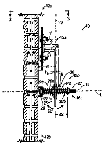
Brief D~scri~s .ion of a ra tjn,,~g
Figure 1 is a cross-sectional side view of art apparatus for coupling two
panels of a
building according to the present invention.
Figure 2 is a front view of the apparatus of figure 1, taken along a line Z-Z.
]'2 t ~l ~s~ r' i n of a P f -rre Embad'ment
Referring to Figure 1, an apparatus 10 for coupling two wall panels 12a, 12b
of
building according to the present invention is shown. Panels such as the
panels 12 are
typically decorative and applied to sides of a mufti-story bulldinig, such as
pre-cast
concrete or brick spandrel panels and column covers; however, the apparatus l0
may be
employed for coupling other types of decorative or structural panels used in
or on other
types of structures at other locations thereof without departing from the
principles of the
z5 invention. The panels may be joined or attached to the structure in any
manner known in
the art; however, the present invention provides an additional or safety
coupling between
the panels in the event that these prior art connections fail for some of the
panels.
The panels are typically attached to the building so that they abut one
another in a
side-by-side disposition, e.g., the top side of one of the panels abuts the
bottom side of a
5
CA 02451710 2003-12-31
panel thereabove, or the right side of one of the panels abuts the !eR side of
a panel
therebeside. However, the panels may overlap one another, or the sides may be
spaced
apart from one another, and the principles of the invention will remain
applicable.
A coupling assembly is provided according to the invention that includes first
and
second coupling members 15s, 15b for coupling together the panels 12. Each of
the
coupling members 15 is preferably formed of a structural metal such ~s steel
in an elongate
con~guratiore such as but not limited to the respective configurations shown
in the Figure.
With reference to these exemplary eonftgurations and the explanation herein,
persons of
ordinary skill well readily appreciate ltow to provide the features of the
invention in
1 o alternative tonftgurations.
The first coupling member 15a depends from the interior face of a fcrst panel
IZa
from a fixed location "P" thereon. With reference to the typical vertical
orientation of the
panels 12, the first coupling member I Sa extends from the point "P"
downwardly to the
panel 12b below. The first coupling rrtember is adapted to provide a large
deflection 5L
that is associated with bending ofthe member about the point. "P" in the plane
ofFigure 1,
particularly at an end 25 thereof. The force producing this bending is applied
by the
second coupling member 15b as described below.
The frst coupling rreernber ISa is preferably adapted to provide for a large
deflection 8L by providing an effective length "s" of the sztember that is
substantially larger
2 o than a representative cross-sectional thielrness "t~" of the member over
the length "s."
The thickness "tL" is defined in the plane of Figure 1 and need not be
constant. This
6
CA 02451710 2003-12-31
configuration effectively multiplies any deformation at the point "P" (where
bending stress
on the member 15a will be greatest) by a factor oFs/tL. Accordingly, the
amount of
deflection 8L may be much greater than the amount of deformation or strain
that the
coupling member can endure without breaking. Typically, the thickness "tL" is
at least
about 50 - 100 times less than the distance "s." However, a ratio of about 10
or more in
the dimensions "s" and "tL" is sufficient for the differences between these
dimensions to be
considered substantial for purposes herein, providing for a relatively Large
deflection as a
result of bending of the first coupling member in the pertinent plane.
For small earthquakes, deformation ofthe member 1 Sa may be elastic and
therefore reversible, while for larger earthquakes, deformation rriay ineltrde
plastic
deformation which permanently deforms the member. If the stress at the point
"P"
exceeds the limit for elastic deformation and the member plastically deforms
at "P," the
member will become work-hardened at this location, so that further deformation
will
occur elsewhere along the length of the member before the member breaks. This
illustrates a further advantage of employing a relatively long length "s."
That is, work or
strain-hardening at one point causes further deformation to occur in adjacent
points,
thereafter hardening the adjacent poims and so on over the length "s," rather
than the
member simply breaking at the one point in response to further application of
farce.
To provide the desired range of deflection ~L, the end ~5 of the first member
1 Sa
in a neutral, unstressed position (shown in Figure 1) is spaced from the panel
12b a
distance "d 1 " that is preferably at Least etlual to a first predetermined
maximum amount of
7
CA 02451710 2003-12-31
the deflection SL. In the example ofFigure 1, this deflection is associated
with rotation of
the member 1 Sa about the point "P" in the plane of Figure 1 in the clockwise
direction,
i.e., toward the panel lZb. The spacing "dl" may be provided by an outwardly
extending
portion "R" of the first coupling member as shown in Figure 1, or may be
similarly
provided simply by spacing the coupling member away from the panel 12a, as one
alternative.
The second coupling member 15b depends from the interior face of the second
panel 12b and includes an extension portion 15c that extends outwardly from
the panel
12b, preferably, along the axis "L>" which is perpendicular to the panel.
The extension portion 15c is provided to extend a distance "d2" beyond the
unstressed position of the end of the~flrst coupling member that is preferably
at least equal
to a second predetermined maximum amount of the deflection SL. In the example
of
Figure 1, this deflection is associated with rotation ofthe member 15a about
the point "P"
in the plane ofFigure 1 in the counterclockwise direction, i.e., away from the
panel 12b.
z 5 A coupling mechanism is provided between the couplir~ members that is
maintained over the range of deflection between the first and second maxima of
SL, the
coupling mechanism providing for transmitting a force between the coupling
members
over this range.
Tlza extension portion of the second coupling member extends through an
aperture
z o 16 through the first coupling member so that a first portion "P 1" of the
extension portion
1 Sc is disposed on one side of the first coupling member 15a and extends at
least the first
8
CA 02451710 2003-12-31
distance "dI" and a second portion "P2"~ofthe extension portion is disposed on
the other
side of the first coupling member and preferably extends at Least the second
distance "d2"
from the end 2S of the first coupling member in the unstressed position.
A spring 26 of any desired configuration may be provided at any appropriate
location to bias the second coupling member toward its unstressed position.
Preferably, at
least one coil spring receives therethrough or has its coifs disposed about a
selected one of
the portions of the second member. More preferably, two springs 26a, 26b are
provided,
each having coils disposed about a respective one of the portions of the
second member,
to double the strength of the spring bias. ~ne of the springs 26a is captured
between the
2 o panel 12b and the end 25 of the first coupling member, and the other
spring 26b is
c$ptured between the end 25 and an end 2'7 of the extension portion 15c member
as
shown in Figure 1.
Without departing from the principles ofthe invention, however, ~. simple
exempts
of a coupling mechanism that m$y provide the above-described function is a
pair of nuts
provided on a threaded extension portion i Sc of the second coupling member,
disposed on
opposite sides of the aperture t 6. All deflection would be accommodated in
this example
by bending of the first coupling member.
Since the deflection 8L is enabled by the configuration of the member 1 Sa to
be
relatxVely large without risk of breaking the member 1 Sa, relatively large
translations of the
2 D pane! 12b with respect to the panel 12a along the axis "L" are
accommodated by the
apparatus 10.
p
CA 02451710 2003-12-31
To provide far deflection in a lateral axis, the second coupling member 15b is
attached to the panel 12b so that it is constrained to translate horizontally
along the panel
along an axis "1" that is perpendicular to the plane of Figure 1 and that is
shown in Figure
2. One suitable embodiment of the coupling member I 5b for this purpose
comprises a
cylindrical rod I 8 for use as the extension portion 15c extending along an
axis "L" that is
perpendicular to the panel I 2b. The rod has a head 2a of target diameter than
the cross-
sectional diameter of the rod, such as where the rod is ~ bolt. The head of
the rod is
captured by rides slidingly in a channel Z2 attached to the panel 12b. The
channel has a C-
shaped cross-section for slidingly receiving the head of the rod. Other
structures
1 o providing the same or similar features may be employed without departing
from the
principles of the invention,
Relative movement of the panels I2 along the axis "J" may be accommodated by
translation of the extension portion 1 Sc such as by sliding as provided in
the preferred
embodiment. Although other structures may provide for this translation, the
preferred
1 s bolt and channel is economical. Such translation is, however, resisted by
the coupling
member I 5a at the aperture 16, by a deflection 5J that is associated wish
bending of the
member about the point "P" in the plane of Figure 2 at the end 25. As for the
deflection
8L, the deflection SJ is maximized by providing that the thickness "t," of the
coupling
member 1 Sa, defined in the plane of Figure 2, for rotation of the member 1 Sa
about the
2 0 point "P" in this plane, is small relative to the effective length "s" of
the member, Also
similarly to the deflection aL, the deflection 6J multiplies the deformation
at "P" along the
CA 02451710 2003-12-31
"J" axis by the factor s/t~ to provide for large relative movements of the
patlels along the
"r' axis.
Preferably, both deflections SL arid a1 are maximized in the manner described
abov~; however, since deflections along the "L" and "J" axes are independent
of one
another, just one of these deflections may be selected for maximization where
this is
desirable, e.g., where there are geoiogicai or structural reasons for it being
unnecessary to
accommodate deflections equally along the two axes. For example, the coupling
member
1 Sa may be a piece of sheet metal oriented so that it is characterized by a
larger t~ while
retaining a small t~ (such as shown in Figure 1 ), so that SL is greater than
~J.
1 o A relative movement ~V of the panels 12 along a vertical axis "V" is
preferably
accommodated by forming the aperture I6 as a slot having a vertical
orientation, The
height °'h" of the slot is selected to provide the desired freedom
ofmovement, s~V""=.
lvloreover, if such relative movements exceed the range provided by the slot,
the length
"s1" of that portion of the coupling rnensber 15 a that functions as a Lever
for torque applied
about the point "P" as a result, may functiat~ analogously to provide an
additional
deflection c~Va along the axis V as does the length "s" for the deflection 8L.
As just one
alternative to forming the aperture 16 as a slot, the aperture 15 may simply
be a circular
hale having a diameter "h."
The apparatus 10 is its entirety is seen to provide for large relative
movements of
2 o the panels along three orthogonal axes, ''L," "J," and "Y" while retaining
$ coupling
therebetween. This is particularly useful for maintaining the integrity of the
coupling
m
".,.. ..,... . w. owemmnn;:u% AC .a'~.~.~~,'k.MIA
,v~qmpy-yyaCo-td~> ' .n.~.mRla~' "wai
CA 02451710 2003-12-31
during an earthquake and, therefore, preventing or minimizing injury and
property
damage. The invention may also be useful to accomrnodate for other natural or
man-made
stresses to which the structure rnay be subjected, such as wind or blast.
However, as
mentioned above in connection with the deflections 8L and 8J, any selected
Limited set of
s the deflections cSL, 8J, SV, and SVa rrsay be provided in accord with a
design choice for a
particular structure in particular geologic or other environmental conditions
by an
apparatus according to the present invention without departing from the
principles thereof.
It is to be recognized that, while a particular method and apparatus for
coupling
panels to a structure has been shown and described as preferred, other
configurations and
z o methods could be utilized, in addition tp those already mentioned, without
departing from
the principles of the invention.
The terms and expressions which have been employed in the foregoing
specifscation are used therein as terms of description and not of limitation,
and there is no
intention of the use of such terms and expressions of excluding equivalents of
the features
15 shown and described or portions thereof, it being recognized that the scope
of the
invention is def ned and limited only by the claims which follow.
1Z