Note: Descriptions are shown in the official language in which they were submitted.
CA 02451751 2003-12-23
A closure device with a uiercin~ element
The present invention relates to a closure device of plastic which may be
attached via a
piercable location of a closed receptacle and which consists of a bung-like
lower part with a
cylindrical pour-out spout which is connected or connectable to the
receptacle, and of a screw
cap which may be pushed onto the lower part, as well as of a cylindrical
piercing element which
in the axial direction is open on both sides and which is displaceably mounted
in the lower part,
wherein in the screw cap there are present means which during the screwing-off
movement of
the screw cap for the first time move the piercing element helically
downwards.
Closure devices of plastic consisting of three parts, as described above,
specifically of a
bung-like lower part with a cylindrical pour-out spout, of a cylindrical
piercing element movable
therein and of screw cap which comprises means in order to move the piercing
element are
known in the most varied of embodiment forms. Such closure devices are
attached to soft-
packaging receptacles. The receptacles consist of mufti-layered films which
usually have one or
more paper or cardboard layers, one or more plastic film layers and at least
one blocking layer,
for example of aluminium. In the region of the closure devices to be attached
the packaging
comprise suitable pre-punched piercing locations. Usually according to the
piercing element of
the closure device mostly only the innermost-lying compact plastic film layer
and the aluminium
layer need to be severed.
With most known embodiment forms the piercing element is designed such that
the
piercing element merely exerts a translatory movement towards the inside of
the packaging. For
example EP-A-0'328'652 (Toppan Printing Co. Ltd) shows a solution in which in
the screw cap a
guide-path-like helical line is centrically incorporated on an inner wall,
whilst the piercing
element has a similar counter-running thread and whereas simultaneously the
piercing element is
provided with cams which prevent a rotation relative to the pour-out bung. A
solution acting in a
practically equal manner is also known from WO 99/62776 (Crown Cork and Seal
Technologies
Corp.). Also from GB-2241224 there is known a closure device with a bung-like
pour-out in
which there runs a piercing element with guide cams, wherein the guide cams
engage into axially
running grooves whilst simultaneously the piercing element comprises an inner
thread which
cooperates with a centric annular wall of the screw cap, wherein the centric
wall comprises an
outer thread. Simultaneously a threaded connection exists between the screw
cap and the pour-
out bung.
The last-mentioned solution according to GB-A-2241224 does not fimction with a
piercable location in the packaging but the pour-out bung is already welded
from the inside to the
inner wall of the packaging and an additional film is attached on the inside
on the flange of the
pour-out bung. Such a closure film may have any properties which differ from
the actual
1
CA 02451751 2003-12-23
packaging. Accordingly the shaping of the piercing element may be practically
infinite as is for
example in the solution according to the Figure 1 of this publication, or
there may be provided
several perforation teeth on the circumference of the piercing element.
Completely analogous to
this, in the, embodiment form according to EP-A-0'328'652 there is shown a
piercing element
which comprises a multitude of perforation teeth on the lower edge. The same
is also the case
with WO 99/62776 which has likewise akeady been mentioned.
In contrast to the previously mentioned protective patent rights WO 95/05996
(International Paper Company) shows a closure device with which the piercing
element does not
only carry out a purely translatory movement but a screw movement. The
piercing element
accordingly comprises an outer thread which is meshingly guided into an inner
thread in the
pour-out bung. The piercing element may be set into a corresponding screw
movement by way
of lug means in the screw cap. If the screw cap is screwed off, then the
piercing element moves
simultaneously in a screw movement downwards into the receptacle to be opened.
Here too the
piercing element along its lower edge has a multitude of perforation teeth in
a completely
analogous manner to the previous known solutions.
Practically all closure devices obtainable on the market today of the type of
interest here
have given rise to great problems. Whilst initial solutions not documented
here fimctioned
practically without perforation teeth and with which the receptacle wall was
destroyed
somewhere, with perforation teeth one believed that one could come to terms
with the problem.
This however was not the case. One of the main reasons lies in the fact that
all solutions demand
a large force effort on opening. Practically with all solutions, over the
whole circumference many
locations of the films are simultaneously perforated. If the teeth were
located at exactly those
locations which are located vertically above the pre-separated film, then a
solution would be
possible. This however would demand a fastening of the closure device onto the
receptacle
which is exact to practically a tenth of a millimetre. This is simply not
possible. Accordingly the
teeth also dig into regions of the packaging which are not pre-punched. For
this not only is
considerably more force required but also at the same time a pure pulling
movement to the film
is effected. Whilst films mostly react sensitively to perforations, most films
are extraordinarily
resistant to tension forces.
With the embodiment according to WO 95/05996 is was riot recognised that with
the
solution cited here, essentially a cutting effect is achieved instead of a
piercing effect.
Accordingly the concept with a multitude of perforation teeth in itself
doesn't make sense. Added
to this is the fact that already with a small rotational angle the complete
inner region is cut out of
the packaging and falls into the contents of the receptacle. This is not only
undesirable and
unhygienic, but it additionally leads to the fact that during the pouring-out
the loose part again
and again gets into the pour-out region and leads to uncontrollable pour-out
characteristics.
2
CA 02451751 2003-12-23
As a result of this it, is the object of the present invention to improve a
closure device of
the initially cited type in a manner such that a simple opening is possible,
with which
simultaneously the disadvantages described further above may be avoided.
A closure device which has the features of patent claim 1 achieves this
object.
With the selection of the offset angle a with a size of less than 180°
it is ensured that no
complete separation out of the packaging region is possible, whereas with a
selection of the
offset angle of more than 100° it is ensured that at the moment at
which the displacing element
becomes effective, more than half the circumference is severed and thus the
already severed part
may be folded away. The latter would also be given per se, even if the offset
angle were to be
less than 100°, but on the one hand there is the great danger that the
displacing element not only
pushes the already separated region to the side, but also simultaneously would
cause the region
not yet severed to tear. Finally however on the other hand with an offset
angle of less than 100°
the open pour-out region would be greatly restricted.
Further advantageous design forms of the subject matter of the invention are
to be
deduced from the dependent claims and their significance and manner of acting
is explained in
the subsequent description with reference to the accompanying drawings.
In the drawing there is shown one preferred embodiment form of the subject-
matter of
the invention. There are shown in:
Figure 1 a vertical section through the closure device in the assembled
condition on a
receptacle, before opening for the first time and
Figure 2 the same closure device after opening for the first time, with a
screwed-off screw
cap, again in the assembled condition in a diametrical vertical section.
Figure 3 shows the piercing element in the position of manufacture connected
as one piece
to the lower part, again as a diametrical vertical section, whilst
Figure 4 shows the closure device in the assembled condition in the position
of use,
wherein merely the packaging is shown partly sectioned.
Figure 5 and
Figure 6 represent schematic cutting and bending plans for two different
offset angles a.
3
CA 02451751 2003-12-23
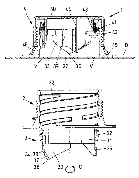
Although the invention is essentially concerned only with the design of the
piercing
element, for a better understanding of the whole construction the closure
device 1 consisting of
three parts is shown. These are a lower part 2, which is adheringly attached
to the receptacle B, a
piercing element 3 which is screwably movably mounted therein and a screw cap
4 engaging
over the lower part 2. The lower part 2 has a cylindrical pour-out spout 20,
which at the end
merges into a lower flange 21 and comprises an inner thread 22 as well as an
outer thread 23.
'The flange 21 serves for the adhering connection to the receptacle B. This
receptacle consists of
a mufti-layered soft packaging manufactured of films, wherein the mufti-
layered film comprises
a so-called pre-punching V which partly passes through one or more layers and
thus defines a
nominal opening. For opening the receptacle B as a result the mufti-layered
film has yet to be
completely severed in the region of the pre-punching V. The flange 21 of the
lower part may be
welded or adhered on the mufti-layered film of the receptacle B. The pre-
punching V defines a
circular surface which is to lie within the opening of the cylindrical pour-
out spout 20. The
diameter of the pre-punching V is a few percent smaller than the diameter of
the pour-out spout
20. In contrast the diameter of the pre-punching V corresponds extremely
accurately to the
diameter of the piercing element 3 or the circular path which the cutting
elements of the piercing
element define with their movement. The inner thread 22 of the cylindrical
pour-out spout 20 is a
coarse thread. This means that on the one hand the thread height is relatively
large and the thread
as a result has a larger pitch. As a result of this, already with a rotation
of about 360° or less the
piercing element 3 is moved from its original assembly position, as
represented in Figure 1, into
the lower position of use according to Figure 2. Accordingly the outer thread
23 is realised as a
so-called fine thread. Accordingly the thread 23 only has a slight height of
the thread flanks and
the pitch of the thread is flat. As a result of this, in order to screw off
the screw cap 4 this needs
to undergo several rotations.
The actuation of the piercing element 3 is effected by way of the screw cap 4.
The screw
cap 4 has a cover surface 40 on which a circumferential outer wall 41 borders.
The outer wall 41
has an inner thread 42 which is designed as a fine thread, matching the outer
thread 23 of the
cylindrical pour-out spout. An annular wall 43 running concentrically to the
outer wall 41 is
integrally formed on the lower side of the cover surface 40. Means in the form
of lugs 44 are
integrally formed on this concentric annular wall 43 which has a diameter
which is smaller than
the inner diameter of the piercing element. With a rotation of the screw cap 4
the lugs 44 drive
the piercing element 3 in a counter-tanning direction. Whilst the screw cap 4
moves upwards, the
piercing element is moved downwards since the threads between the screw cap 4
and lower part
2 are orientated running counter to the rotational direction of the thread
between the piercing
element 3 and the Lower part 2. A guarantee strip 45 is integrally formed at
the bottom on the
outer wall 41 via break-off bridge locations 46. This is held in the secured
position by retaining
cams 24 and the guarantee strip 45 remains here even after opening for the
first time, as this is
evidentin Figure 2.
4
CA 02451751 2003-12-23
The piercing element 3 which as shown in Figure 3 is advantageously
manufactured with
the lower part as one piece consists essentially of an annular wall part 31
with an outer thread 32
which again is designed as a coarse thread, matching the inner thread 22 of
the lower part 2. At
least two cutting elements 33 and at least one displacing element 34, 35 are
integrally formed on
this annular wall part 31. The displacing element 34 may be combined with the
cutting element
33 or, as is evident from Figures 1 to 3 may be designed as a separate element
35. In the section
drawings according to Figures 1 to 3 in each case only one cutting element 33
may be
recognised. Only in the lateral view according to Figure 4 are both cutting
elements 33 visible.
The cutting elements 33 which roughly have a triangular shape open into an
terminal perforating
tooth 36. An arrow D in each case shows the rotational direction of the
piercing element. A
cutting edge 37 connecting directly to the perforation tooth is integrally
formed on the edge at
the front in the rotational direction. The cutting edge 37 with the preferred
embodiment form
here merges into a displacing edge 38 which thus here forms the displacing
element 34 and is
thus a part of the cutting element 33. On the inner surface of the cutting
element 33 above the
cutting edge 37 there is integrally formed a lug thickening 39 on which a lug
44 bears during the
screwing-off movement of the screw cap for the first time and thus sets the
piercing element 3
into a screw movement. The solution with the displacing edge 38 is merely
optional. As already
mentioned, and likewise realised here, an additional, separate displacing
element 35 may be
provided. The displacing element 35 is designed shorter in the axial direction
of the piercing
element 3 than the cutting element 33. Accordingly the displacing element 35
only comes into
contact with the film of the receptacle B when the two cutting elements 33
have at least
approximately formed a continuous cutting line. The separate displacing
element 35 otherwise
has roughly the shape of the cutting elements 33, but is however formed
bluntly cornered and has
no perforation tooth but runs in a rounded arc.
The manner of acting of the closure device according to the invention is
subsequently
explained with reference to the Figure S and 6. The two cutting elements 33
are arranged
following one another by an offset angle a. In the initial position before
opening the closure
device for the first time the two perforation teeth 36 of the two cutting
elements 33 are located at
the positions a' and b'. After a certain advance angle f3 the two perforation
teeth 36 contact the
film of the receptacle to be severed at the points A and B. With reference to
the rotational
direction D the perforation tooth of the one cutting element runs ahead of the
second cutting
element by an offset angle a. With a further rotation in the direction D the
perforation teeth 36
pierce the film and in the further course sever the film, wherein the one
cutting element runs
through the cutting path from point A to point B, whilst the other cutting
element defines a
cutting line from point B to point C. Thus as soon as the piercing element has
been rotated by the
offset angle a there results a continuous cutting line of 2a which extends
from point A to point C.
In this position the cutting edge 37 has inwardly penetrated the film of the
receptacle at least
CA 02451751 2003-12-23
approximately completely, and the displacing edge 38 and/or the displacing
element 35 now act
from point C. The displacing edge now acts from point C whilst the displacing
element 35 in the
region VB which lies relatively close to the pre-punching V in the not yet
severed region. Then
the region cut free is pressed down into the receptacle in the manner of a
flap. At the same time
the pre-punching V practically serves as a bending line. This situation is for
example evident in
Figure 2. The remaining, non-severed region of the pre-punching V is larger or
smaller,
according to the choice of the offset angle a. 'The offset angle a must
theoretically be at least 90°,
however this is not sufficient in practice and the actual minimum size of the
offset angle a must
be larger than 100°. The offset angle a must of course be smaller than
180° in order to ensure
that the cutting line is not circumferential and as a result a complete round
part is cut out of the
film which could fall into the receptacle. Realistically the maximal offset
angle a may be about
170°. The solutions shown in Figures 5 and 6 relate to realistic
details. If one operates with a
separate displacing element 35 then the offset angle a may tend to be smaller
since in this case
the displacing element may already press onto the film before the cutting
element at the front in
the rotational direction has reached the point C, by which means the film is
pressed slightly
downwards and thus a somewhat longer continuous cutting line arises than the
theoretical cutting
line.
In comparison to the previously known piercing elements with a multitude of
perforation
teeth, the perforation here is effected only at two points. This has the
advantage that the required
force is smaller. Simultaneously, here a real cutting movement is effected.
The cutting edge 37
specifically carnes out a movement component perpendicular to the cutting line
as well as a
component in the direction of the cutting line. However, because the pre-
punching V also runs
relatively close to the relatively rigid connection of the film to the flange
21 of the lower part 2 a
certain shear force is effected.
Of course the gradient of the coarse thread between the piercing element 3 and
the lower
part 2 needs to be directed to the geometry of the cutting elements. The
purely vertical length of
the cutting edge 37 must be equal to the thread pitch which corresponds to the
angle a. The latter
is particularly the case if the displacing element is combined with the
cutting elements
6
CA 02451751 2003-12-23
LIST OF REFERENCE NUMERALS
1 closure device
2 lower part
3 piercing element
4 screw cap
20 pour-out spout, cylindrical
21 flange
22 inner thread
23 outer thread
24 retaining cam
31 annular wall part
cylindrical
32 outer thread
33 cutting elements
34 displacing element
35 separate displacing
element
36 perforation tooth
37 cutting edge
3g displacing edge
39 lug thickening
40 cover surface
41 outer wall
42 inner thread
43 concentric annular
wall
44 lug
45 guarantee strip
46 break-off bridge
locations
receptacle
pre-punching
7