Language selection

Search

Patent 2451871 Summary

Third-party information liability

Some of the information on this Web page has been provided by external sources. The Government of Canada is not responsible for the accuracy, reliability or currency of the information supplied by external sources. Users wishing to rely upon this information should consult directly with the source of the information. Content provided by external sources is not subject to official languages, privacy and accessibility requirements.

Claims and Abstract availability

Any discrepancies in the text and image of the Claims and Abstract are due to differing posting times. Text of the Claims and Abstract are posted:

  • At the time the application is open to public inspection;
  • At the time of issue of the patent (grant).
(12) Patent Application: (11) CA 2451871
(54) English Title: GUTTER CORNER OVERFLOW DEFLECTOR
(54) French Title: DEFLECTEUR DE DEBORDEMENT POUR COIN DE GOUTTIERE
Status: Deemed Abandoned and Beyond the Period of Reinstatement - Pending Response to Notice of Disregarded Communication
Bibliographic Data
Abstracts

English Abstract


A corner deflector for use with an eaves trough wherein the eaves trough is
located
proximate a valley in a roof, the deflector comprising first and second
segments with a
fold line separating the segments, at least one flange extending outwardly
from a bottom
edge of each of the segments, the flange being such as to permit securement to
a gutter
guard used with the eaves troughs. The deflector prevents overflow at the
corners
associated with roof valleys.


Claims

Note: Claims are shown in the official language in which they were submitted.

The embodiments of the invention in which an exclusive property or privilege
is
claimed are defined as follows:
1. A corner deflector suitable for use with a gutter, said corner deflector
comprising:
a generally planar member having an upper edge and a lower edge, said member
having first and second segments, said first and second segments being
separated by a fold
line, said fold line extending from said top edge to said bottom edge; and
at least one flange extending outwardly from said bottom wall of each of said
segments, said flange extending outwardly in a direction substantially
perpendicular to said
planar portion.
2. The corner deflector of Claim 1 wherein each of said segments has one
inwardly
extending flange and one outwardly extending flange extending from said bottom
edge.
3. The corner deflector of Claim 2 wherein said first segment and said segment
are
symmetrical about said fold line.
4. The corner deflector of Claim 2 wherein said deflector is formed of a
metallic material.
5. The corner deflector of Claim 2 wherein said top edge has a arcuate
outline.
6. In an eaves trough having a gutter guard associated therewith, said guard
comprising
a foraminous member covering a top of the gutter and wherein said gutter has
two mutually
perpendicular sections, the improvement comprising a corner deflector, said
corner deflector
having a first segment and a second segment, a fold line separating said first
and second
segments, said first and second segments lying in mutually perpendicular
planes;
at least one inwardly extending flange and one outwardly extending flange
being
located along a bottom edge of each of said segments, said inwardly extending
flange being
secured to said gutter guards.
-5-

7. The improvement of Claim 6 wherein said corner deflector is formed of a
metallic
material.
8. The improvement of Claim 6 wherein said first and second segments are
symmetrical
about said fold line.
9. The improvement of Claim 6 wherein each of said first and second segments
has an
upper edge which an arcuate configuration.
6

Description

Note: Descriptions are shown in the official language in which they were submitted.


CA 02451871 2003-12-02
GUTTER CORNER OVERFLOW DEFLECTOR
FIELD OF THE INVENTION
The present invention relates to an eaves trough or gutter, and more
particularly,
relates to an improvement in such structures.
BACKGROUND OF THE INVIJNTION
Gutters or eaves troughs are widely used on many building structures and in
particular
for residential buildings. The gutters or eaves troughs are; designed to catch
the rain falling
on a sloping roof and transport the water to a down spout where it may be
safely discharged
away from the house's foundation.
Generally, such systems work as they are designed to. However, occasionally
problems are encountered due to a larger volume of water - i.e. the capacity
of the gutter is
exceeded. This can occur particularly when a so-called gutter shield or guard
is utilised. In
such an arrangement, the apertures in the guard naturally reduce the rate of
transmission of
the rain water to the eaves troughs. This problem is further accentuated when
the roof or
structure has a valley structure which is a frequent occurrence in residential
structures. Thus,
the volume of water is increased and concentrated at one :location.
Accordingly, there is an
overflow which occurs.
SUMMARY OF THE INVENTION
It is therefore an object of the present invention to provide a gutter corner
overflow
deflector which helps overcome the problem of gutters or eaves troughs
overflowing when
a valley in the roof occurs.
According to one aspect of the present invention, there is provided a corner
deflector
suitable for use with a gutter, the corner deflector comprising a generally
planar member
-1-

CA 02451871 2003-12-02
having an upper edge and a lower edge, the member having first and second
segments, the
first and second segments being separated by a fold line, the fold line
extending from the top
edge to the bottom edge and at least one flange extending outwardly from the
bottom wall of
each of the segments, the flange extending outwardly in a direction
substantially
perpendicular to the planar portion.
According to a further aspect of the present invention., there is provided an
eaves
trough having a gutter guard associated therewith, the guard comprising a
foraminous
member covering a top of the gutter and wherein the gutter has two mutually
perpendicular
sections, the improvement comprising a corner deflector, the corner deflector
having a first
segment and a second segment, a fold line separating the first and second
segments, the first
and second segments lying in mutually perpendicular planes, at least one
inwardly extending
flange and one outwardly extending flange being located along a bottom edge of
each of the
segments, the inwardly extending flanges being secured to the gutter guards.
The corner deflector of the present invention may be formed of any suitable
material
and would conveniently be manufactured either of a metallic or plastic
material. Thus, both
materials are known for use in gutters and one may then use either a similar
or dissimilar
material.
The corner deflector of the present invention is particularly suited to use
with eaves
troughs or gutters having a guard member lying on the top thereof. The guard
member is
usually a piece of material having a plurality of apertures extending
theretrough and is
designed to protect the eaves trough or gutter from extraneous material such
as leaves and the
like. In one particular embodiment, the corner guard of the present invention
is particularly
suited for use with a structure such as is shown in co-pending U.S.
Application 10/261,043,
-2-

CA 02451871 2003-12-02
the teaching of this application being incorporated herein by reference.
BRIEF DESCRIPTION OF THE DRAVv'INGS
Having thus generally described the invention, reference will be made to the
accompanying drawings illustrating an embodiment thereof, in which:
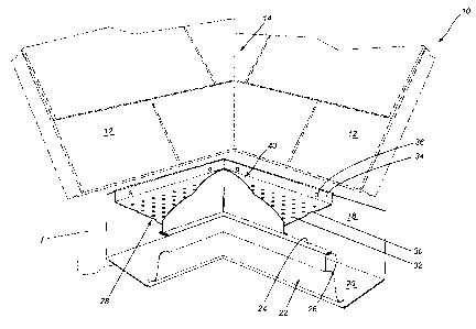
Figure 1 is a perspective viev~~ of a portion of a roof and an eaves trough
structure
having the corner guard of the present invention;
Figure 2 is a perspective view of the corner guard;
Figure 3 is a side elevation view, partially in section, of the gutter corner
guard of the
present invention placed on an eaves trough; and
Figure 4 is a top plan view of a gutter having the corner guard of the present
invention
thereon.
DESCRIPTION OF THE PREFERRED EMI30DIMENTS
Referring to the drawings in a greater detail and by reference characters
thereto, there
is illustrated in Figure 1 an arrangement utilising the deflector of the
present invention. Thus,
there is provided a roof generally designated by reference numeral 10 and
which has a
plurality of shingles 12 thereon in a conventional arrangennent. Roof 10 is
constructed such
that a valley 14 is formed between two roof sections.
A gutter generally designated by reference numeral I 6 is secured to the facia
F of the
roof. Gutter 16 has a back wall 18, a bottom wall 20, and a front wall
generally designated
by reference numeral 22. At the upper edge of front wall 22, there is provided
a top wall 24
and which terminates in an inwardly extending flange 26.
Extending over gutter I6 is a gutter guard generalh~ designated by reference
numeral
28 and which gutter guard includes a central planar portion 30 having a
plurality of apertures
-3-

CA 02451871 2003-12-02
32 formed therein. A side wall 34 extends upwardly from gutter guard 28 and
screws 36 are
used to attach gutter guard 28 and gutter 16 to the building structure under
facia F.
The corner deflector of the present invention is generally designated by
reference
numeral 40. Corner deflector 40 has a first segment 42 and a second segment 44
which are
separated by a fold line 46. Each segment 42, 44 has a top edge 48, 50
respectively. As may
be seen in the drawings, top edges 48 and 50 are arcuate in nature to provide
a pleasant
aesthetic appearance.
First segment 42 includes an inner flange 52 and an outer flange 54 formed
along a
bottom edge thereof. Similarly, second segment 44 includes an inner flange 56
and an outer
flange 58. As may be seen in Figure 3, outer flanges 54 and 58 are designed to
fit under
flange 26 extending from top wall 24 of the gutter 16 and to thereby be
secured in place.
Inner flanges 52 and 56 are secured to central planer portion 30 by means of
screws 60.
As will be appreciated, the above arrangement provides a corner deflector 40
which
may be easily assembled and secured to the gutter 16 and associated
components. The
installer will have little trouble doing so and it provides a method of
overcoming the problems
at the valleys in the roof.
It will be understood that the above described embodiment is for purposes of
illustration only and that changes and modifications may be made thereto
without departing
from the spirit and scope of the invention.
-4-

Representative Drawing
A single figure which represents the drawing illustrating the invention.
Administrative Status

2024-08-01:As part of the Next Generation Patents (NGP) transition, the Canadian Patents Database (CPD) now contains a more detailed Event History, which replicates the Event Log of our new back-office solution.

Please note that "Inactive:" events refers to events no longer in use in our new back-office solution.

For a clearer understanding of the status of the application/patent presented on this page, the site Disclaimer , as well as the definitions for Patent , Event History , Maintenance Fee  and Payment History  should be consulted.

Event History

Description Date
Revocation of Agent Requirements Determined Compliant 2021-04-01
Application Not Reinstated by Deadline 2006-12-04
Time Limit for Reversal Expired 2006-12-04
Inactive: IPC from MCD 2006-03-12
Deemed Abandoned - Failure to Respond to Maintenance Fee Notice 2005-12-02
Application Published (Open to Public Inspection) 2005-06-02
Inactive: Cover page published 2005-06-01
Inactive: First IPC assigned 2004-02-09
Application Received - Regular National 2004-01-23
Filing Requirements Determined Compliant 2004-01-23
Inactive: Filing certificate - No RFE (English) 2004-01-23

Abandonment History

Abandonment Date Reason Reinstatement Date
2005-12-02

Fee History

Fee Type Anniversary Year Due Date Paid Date
Application fee - small 2003-12-02
Owners on Record

Note: Records showing the ownership history in alphabetical order.

Current Owners on Record
GUY BROCHU
Past Owners on Record
None
Past Owners that do not appear in the "Owners on Record" listing will appear in other documentation within the application.
Documents

To view selected files, please enter reCAPTCHA code :


To view images, click a link in the Document Description column. To download the documents, select one or more checkboxes in the first column and then click the "Download Selected in PDF format (Zip Archive)" or the "Download Selected as Single PDF" button.

List of published and non-published patent-specific documents on the CPD .

If you have any difficulty accessing content, you can call the Client Service Centre at 1-866-997-1936 or send them an e-mail at CIPO Client Service Centre.


Document
Description 
Date
(yyyy-mm-dd) 
Number of pages   Size of Image (KB) 
Description 2003-12-01 4 191
Claims 2003-12-01 2 60
Abstract 2003-12-01 1 14
Drawings 2003-12-01 3 72
Representative drawing 2005-05-04 1 17
Filing Certificate (English) 2004-01-22 1 160
Reminder of maintenance fee due 2005-08-02 1 109
Courtesy - Abandonment Letter (Maintenance Fee) 2006-01-29 1 174