Language selection

Search

Patent 2451916 Summary

Third-party information liability

Some of the information on this Web page has been provided by external sources. The Government of Canada is not responsible for the accuracy, reliability or currency of the information supplied by external sources. Users wishing to rely upon this information should consult directly with the source of the information. Content provided by external sources is not subject to official languages, privacy and accessibility requirements.

Claims and Abstract availability

Any discrepancies in the text and image of the Claims and Abstract are due to differing posting times. Text of the Claims and Abstract are posted:

  • At the time the application is open to public inspection;
  • At the time of issue of the patent (grant).
(12) Patent: (11) CA 2451916
(54) English Title: OBJECT DETECTION SYSTEM AND METHOD
(54) French Title: SYSTEME ET PROCEDE DE DETECTION D'OBJETS
Status: Expired and beyond the Period of Reversal
Bibliographic Data
(51) International Patent Classification (IPC):
  • G01S 13/00 (2006.01)
  • G01S 13/58 (2006.01)
  • G01S 13/92 (2006.01)
(72) Inventors :
  • LLOYD, PETER GREGORY (United Kingdom)
  • HARRIS, GARETH LIAM (United Kingdom)
  • STOTHARD, BRIAN PHILLIP (United Kingdom)
(73) Owners :
  • ROKE MANOR RESEARCH LIMITED
(71) Applicants :
  • ROKE MANOR RESEARCH LIMITED (United Kingdom)
(74) Agent: BORDEN LADNER GERVAIS LLP
(74) Associate agent:
(45) Issued: 2011-04-05
(86) PCT Filing Date: 2002-07-25
(87) Open to Public Inspection: 2003-02-13
Examination requested: 2007-03-02
Availability of licence: N/A
Dedicated to the Public: N/A
(25) Language of filing: English

Patent Cooperation Treaty (PCT): Yes
(86) PCT Filing Number: PCT/EP2002/008334
(87) International Publication Number: EP2002008334
(85) National Entry: 2003-12-23

(30) Application Priority Data:
Application No. Country/Territory Date
0118707.9 (United Kingdom) 2001-08-01
0202412.3 (United Kingdom) 2002-02-04

Abstracts

English Abstract


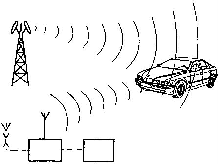
A passive object detection system (1) comprises first and second antennas (4,
6) and a processor (8). The first antenna (4) is adapted to receive a signal
transmitted by a mobile telephone base station; the second antenna (6) is
adapted to receive the signal transmitted by a mobile telephone base station
(2) after it has been reflected off an object (3) and the processor compares
the signal received from the mobile telephone base station with the signal
reflected from the object to derive speed or position information relating to
the object therefrom.


French Abstract

Système passif (1) de détection d'objets comprenant une première et une deuxième antenne (4, 6) et un processeur (8). Cette première antenne (4) est conçue pour recevoir un signal émis par une station de base téléphonique mobile. La deuxième antenne (6) est conçue pour recevoir le signal émis par la station de base téléphonique mobile (2) après avoir été réfléchi par un objet (3) et le processeur compare le signal reçu de la station de base téléphonique mobile au signal réfléchi par l'objet dans le but de calculer des informations de vitesse ou de position concernant cet objet.

Claims

Note: Claims are shown in the official language in which they were submitted.


CLAIMS:
1. A passive method of detecting an object, the method comprising receiving at
a
receiver a first signal transmitted by a mobile phone base station, receiving
at the
receiver a second signal comprising the first signal transmitted by a mobile
phone
base station after it has been reflected off an object; and comparing the
first and
second signals to derive data relating to position or speed of movement of the
object;
the method further comprising providing a plurality of mobile phone base
stations
which transmit a signal, such that as the object moves out of range of one
base station,
it comes into range for another, whereby the distance of the object from a
base station
being used to determine a position of the object remains substantially
constant and
distance of the object from the receiver changes, thereby improving the
received
power and range.
2. A method according to claim 1, the method further comprising a time delay
between receiving the first and second signals, by performing a cross
correlation of
the signal from the first antenna with the signal from the second antenna;
determining
the speed of the target using the Doppler effect; storing results from
successive cross
correlations, and calculating the change in relative phase between the signal
from the
first antenna and the second antenna at the delay of interest.
3. A method according to claim 2, wherein the change in relative phase is
calculated by means of a Discrete Fourier Transform (DFT) or Fast Fourier
Transform
(FFT).
4. A passive detection system, the system comprising a receiver having first
and
second antennas; and processing means; wherein the first antenna is adapted to
receive a signal transmitted by a mobile telephone base station; wherein the
second
antenna is adapted to receive the signal transmitted by the mobile telephone
base
station after the signal has been reflected off an object and wherein the
processing
means compares the signal received from the mobile telephone base station with
the
signal reflected from the object and derives speed or position information
relating to

6
the object therefrom; wherein the object is a moving object; and the system
further
comprises a plurality of mobile phone base stations which transmit a signal,
such that
as the object moves out of range of one base station, it comes into range for
another,
whereby the distance of the object from a base station being used to determine
a
position of the object remains substantially constant and distance of the
object from
the receiver changes, thereby improving the received power and range.

Description

Note: Descriptions are shown in the official language in which they were submitted.


CA 02451916 2003-12-23
'k
~~ r
OBJECT~DETECTION SYSTEM AND METHOD
This invention relates to a system and method for object detection, in
particular for
detecting moving objects.
There are many situations in which it is desirable to detect moving objects
and to
provide position and/or speed information about those objects, for example, to
detect
aircraft, monitor traffic flow or to detect vehicles exceeding the speed
limit. Active radar
systems are often used for these purposes, however this requires RF
transmissions. Use of
RF transmissions has some disadvantages. The transmissions can be detected by
simple
receivers, which gives away the presence of the sensor (e.g. car radar
detectors used by
speeding motorists). Also, there are many legal restrictions on the
transmission of radio
frequencies, which may differ from one country to another, so a system
suitable for use in
one country may be illegal in another.
Passive systems using television transmitters have been proposed, however
these
have certain disadvantages. Although they use high power transmitters, the
objects being
detected are often far away and the received signal power may be weak.
US 5,604,503 describes a method of separating rriultipath signals received at
an
antenna using a signal preprocessor which permits coherent bistatic radar
detection with a
single omnidirectional antenna.
US 6,011,515 describes a vehicle traffic sensor using a roadside antenna to
detect
signals from a transmitter and signals reflected off a vehicle.
In accordance with a first aspect of the present invention, a passive method
of
detecting an object comprises receiving a first signal taransmitted by a
mobile phone base
station, receiving a second signal comprising the first signal transmitted by
the mobile
phone. base station after it has been reflected off an object; and comparing
the first and
second signals to derive data relating to position or speed of movement of the
object; the
method further comprising providing a plurality of mobile phone base stations
which
transmit a signal, such that as the object moves out of range of one base
station, it comes
into range for another, whereby the distance of the object from a base station
being used to
determine a position of the objectremains substantially constant and the
distance of the
object from the receiver changes, thereby improving the received power and
range.
In accordance with a second aspect of the present invention a passive object
detection system comprises first and second antennas; and processing means;
wherein the

CA 02451916 2003-12-23
~. r
~ r
first antenna is adapted to receive a signal transmitted by a mobile telephone
base station;
wherein the second antenna is adapted to receive the signal transmitted by the
mobile
telephone base station after the signal has been reflected off an object and
wherein the
processing means compares the signal received from the mobile telephone base
station
with the signal reflected from the object and derives speed or position
information relating
to the object therefrom; wherein the object is a moving object; and the system
further
comprises a plurality of mobile phone base stations which transmit a signal,
such that as
the object moves out of range of one base station, it comes into range for
another, whereby
the distance of the object from a base station being used to determine a
position of the
object remains substantially constant and the distance of the object from the
receiver
changes, thereby improving the received power and range. .
The present invention covers a passive electronic system which makes use of
the
radio emissions from mobile phone base stations and in particular the
reflection of those
radio waves from objects, such as cars, people and animals, to detect the
location and, iiF
moving, the velocities of those objects. No transmissions from the system are
required
~ANIEI~DEb SHEET:
...~:. .:: ..,: ~ ~...:.:,

CA 02451916 2003-12-23
WO 03/012473 PCT/EP02/08334
2
and the detection system can be carried from place to place and used in
conjunction
with an existing mobile phone base station nearby. It is particularly
beneficial to police
forces enforcing speed limits, that the vehicle cannot detect the existence of
the sensor.
The proliferation of mobile phone bases stations in towns and on main roads
gives good
coverage, in the areas required.
An example of a passive object detection system and method according to the
present invention will now be described with reference to the accompanying
drawings
in which:-
Figure 1 is a plan view of a prior art system;
Figure 2 is a schematic diagram of one example of a passive object detection
system according to the invention;
Figure 3 is a plan view illustrating operation of the system of Fig. 2
Figure 4 illustrates a sensor of the system of Fig. 2 in more detail;
Figure 5 illustrates alternative arrangements for the sensor of Fig. 2; and
Figure 6 is a flow diagram illustrating an algorithm for use in the system of
Fig. 2.
Fig. 1 shows in plan view how a prior art system for detecting objects, in
this
case using a television transmitter, operates. A tv transmitter 20 emits a
signal which
travels a distance Rl and is reflected off an object 21. The reflected signal
travels a
distance Rz and is received at a receiver 22. The power PR of the signal
received at the
receiver 22 can be calculated from the equation:
PR = PT Gl G~ ~z
~4~~3 Rlz Rzz
where PT is is the transmitted power
Gl is the gain of the first antenna
Gz is the gain of the second antenna
6 is the radar cross section of the object of interest
~, is the wavelength of the transmitted signal
Rl is the distance between the transmitter and the object
R2 is the distance between the receiver and the object

CA 02451916 2003-12-23
WO 03/012473 PCT/EP02/08334
In the prior art system using a tv transmitter, when the object is moving away
from the
transmitter the distances R1 and R2 increase at a similar rate, so one can
assume that the
received power PR is proportional to 1/R4, i.e. as the object moves away there
is a fast
and significant reduction in received power.
Figure 2 illustrates how a passive object detection system 1 according to the
present invention is used in conjunction with radio waves transmitted by a
mobile
phone base station 2 and reflected off an object 3. In this example, the
object in
question is a vehicle, but other objects could be sensed equally well. The
object may be
moving or stationary. The system comprises a first antenna 4 which points
directly at
the base station 2 and detects radio waves 5 which have travelled along the
shortest
path. A second antenna 6 points in the direction of the object of interest and
detects
radio waves 7 reflected off that object 3. The antennas may be of any suitable
type,
such as Yagi or phased arrays. A processor 8 analyses the signals received by
the first
and second antennas 4, 6 and compares the phase and frequencies of these two
received
signals. This is illustrated in more detail in Fig. 4. The processor also
measures the time
delay between the two received signals. The signals may then be displayed or
stored.
A display device 9 takes the output of the processor and displays the
information
derived about frequency difference and time delay between the two signals. The
display
may convert the information into distance off and speed of the object, if it
is moving.
A recording mechanism may also be provided. Such a system would be
particularly
useful in monitoring traffic flow.
The advantages of the present invention can be seen from Fig. 3 which is a
plan
view of the system in operation. As in the prior art, there is a receiver 22,
however the
present invention does not rely on a single transmitter. Instead, it takes
advantage of the
proliferation of mobile phone transmitter aerials 23. This has the effect that
instead of
the object moving out of range of the transmitter and so increasing the
distance R1,
when the object moves out of range of one transmitter, it comes into range for
another,
so that the distance Rl remains subtantially constant whilst R2 changes. From
this, PR
can be taken to be proportional to 1/R2, thereby significantly increasing the
received
power. By using transmitters further away from the receiver, the range of the
device is
increased over prior art systems because the target is always close to a
transmitter,
despite mobile phone transmitters operating at higher frequency and lower
power than
tv transmitters.

CA 02451916 2003-12-23
WO 03/012473 PCT/EP02/08334
4
Fig. 4 illustrates the signal processing in more detail. The signal received
by
each antenna 4, 6 is amplified in respective pre-amplifiers 10, 11, then
converted to a
digital signal by analogue to digital converters (ADC's) 12, 13. In practice
the received
signals would probably be mixed down to a lower frequency before being sampled
by
the ADC, for example as shown in Fig. 3.
The output signals from the ADC's 12, 13 are fed into the processor 8, which
may be a digital signal processor or some hardware implementation of the
algorithm
such as an FPGA, EPLD, ASIC or similar. The processor is set up to run an
algorithm
as illustrated in the flow diagiam of Fig. 6. This algorithm has two separate
functions.
Firstly, the algorithm will determine the delay difference between the two
signals, and
secondly it will determine any Doppler shift due to motion of the target.
To determine the time delay the algorithm performs a cross correlation of the
signal from the first antenna with the signal from the second antenna. The
Doppler
effect is then used to determine the speed of the target. To do this the
results from
successive cross correlations are stored, and the change in relative phase
between the
signal from antenna 1 and antenna 2 at the delay (or delays) of interest is
calculated by
means of a DFT (Discrete Fourier Transform) or FFT (Fast Fourier Transform),
or
similar algorithm. The "delays of interest" may include all possible delays
calculated by
the cross correlation.

Representative Drawing
A single figure which represents the drawing illustrating the invention.
Administrative Status

2024-08-01:As part of the Next Generation Patents (NGP) transition, the Canadian Patents Database (CPD) now contains a more detailed Event History, which replicates the Event Log of our new back-office solution.

Please note that "Inactive:" events refers to events no longer in use in our new back-office solution.

For a clearer understanding of the status of the application/patent presented on this page, the site Disclaimer , as well as the definitions for Patent , Event History , Maintenance Fee  and Payment History  should be consulted.

Event History

Description Date
Time Limit for Reversal Expired 2012-07-25
Letter Sent 2011-07-25
Grant by Issuance 2011-04-05
Inactive: Cover page published 2011-04-04
Pre-grant 2011-01-21
Inactive: Final fee received 2011-01-21
Inactive: Office letter 2010-12-03
Notice of Allowance is Issued 2010-12-02
Letter Sent 2010-12-02
Notice of Allowance is Issued 2010-12-02
Inactive: Approved for allowance (AFA) 2010-11-30
Amendment Received - Voluntary Amendment 2010-09-29
Inactive: S.30(2) Rules - Examiner requisition 2010-05-04
Letter Sent 2007-03-28
Amendment Received - Voluntary Amendment 2007-03-12
Request for Examination Requirements Determined Compliant 2007-03-02
All Requirements for Examination Determined Compliant 2007-03-02
Request for Examination Received 2007-03-02
Inactive: IPC from MCD 2006-03-12
Inactive: Cover page published 2004-02-27
Inactive: Notice - National entry - No RFE 2004-02-25
Inactive: Single transfer 2004-02-12
Application Received - PCT 2004-01-23
National Entry Requirements Determined Compliant 2003-12-23
Application Published (Open to Public Inspection) 2003-02-13

Abandonment History

There is no abandonment history.

Maintenance Fee

The last payment was received on 2010-06-02

Note : If the full payment has not been received on or before the date indicated, a further fee may be required which may be one of the following

  • the reinstatement fee;
  • the late payment fee; or
  • additional fee to reverse deemed expiry.

Patent fees are adjusted on the 1st of January every year. The amounts above are the current amounts if received by December 31 of the current year.
Please refer to the CIPO Patent Fees web page to see all current fee amounts.

Owners on Record

Note: Records showing the ownership history in alphabetical order.

Current Owners on Record
ROKE MANOR RESEARCH LIMITED
Past Owners on Record
BRIAN PHILLIP STOTHARD
GARETH LIAM HARRIS
PETER GREGORY LLOYD
Past Owners that do not appear in the "Owners on Record" listing will appear in other documentation within the application.
Documents

To view selected files, please enter reCAPTCHA code :


To view images, click a link in the Document Description column. To download the documents, select one or more checkboxes in the first column and then click the "Download Selected in PDF format (Zip Archive)" or the "Download Selected as Single PDF" button.

List of published and non-published patent-specific documents on the CPD .

If you have any difficulty accessing content, you can call the Client Service Centre at 1-866-997-1936 or send them an e-mail at CIPO Client Service Centre.


Document
Description 
Date
(yyyy-mm-dd) 
Number of pages   Size of Image (KB) 
Claims 2003-12-22 2 77
Abstract 2003-12-22 2 68
Drawings 2003-12-22 4 61
Representative drawing 2003-12-22 1 7
Description 2003-12-22 5 246
Claims 2010-09-28 2 62
Drawings 2010-09-28 4 64
Representative drawing 2011-03-03 1 9
Notice of National Entry 2004-02-24 1 190
Reminder of maintenance fee due 2004-03-28 1 110
Courtesy - Certificate of registration (related document(s)) 2004-03-25 1 105
Reminder - Request for Examination 2007-03-26 1 116
Acknowledgement of Request for Examination 2007-03-27 1 177
Commissioner's Notice - Application Found Allowable 2010-12-01 1 163
Maintenance Fee Notice 2011-09-05 1 170
PCT 2003-12-22 12 423
Correspondence 2010-12-01 1 31
Correspondence 2011-01-20 1 30