Note: Descriptions are shown in the official language in which they were submitted.
CA 02452896 2003-12-11
123068
METHOD AND APPARATUS FOR PERFORMING WELDING
AT ELEVATED TEMPERATURE
This invention relates to the welding of articles, wherein the articles are
maintained at elevated temperature during the welding operation, and more
particularly to the weld repair of superalloy components of gas turbine
engines at
elevated temperature.
BACKGROUND OF THE INVENTION
In an aircraft gas turbine (jet) engine, air is drawn into the front of the
engine,
compressed by a shaft-mounted compressor, and mixed with fiiel. The mixture is
burned, and the hot combustion gases are passed through a turbine mounted on
the
same shaft. The flow of combustion gas turns the turbine by impingement
against
an airfoil section of the turbine blades and vanes, which turns the shaft and
provides power to the compressor. The hot exhaust gases flow from the back of
the engine, driving it and the aircraft forward.
In the most common approach, the turbine blades are cast from nickel-base
superalloys. In service, the turbine blades are subjected to extremely
aggressive
conditions of elevated temperature and harsh environment. It is not uncommon
that some of the airfoil, particularly the portion near the tip, of the
turbine blade is
lost during service by a combination of erosion, corrosion, and oxidation
damage.
As the tip is removed, gas leakage around the turbine blade and thence around
the
turbine increases so that the efficiency of the gas turbine engine decreases.
Because gas turbine blades are expensive to produce as new-make articles,
whenever possible the damaged turbine blades are repaired rather than
scrapped.
The repair involves adding new material to the tip or other damaged portion of
t:he
1
CA 02452896 2008-07-10
123068
turbine blade by welding. In the welding operation, the same material of the
turbine blade (or a different material in some cases) is melted onto the
damaged
area and then allowed to solidify to build up the damaged portion and return
it to
its permitted dimensional range.
Some of the nickel-base superalloys used in turbine blades are subject to
embrittlement and cracking when the welding operation is conducted with the
portion of the turbine blade adjacent to the welded region at a relatively low
temperature. To accomplish the welding of these alloys, a process termed
Superalloy Welding at Elevated Temperature (SWET) has been developed. As
described in US Patent 5,897,801 and 6,124,568, the SWET process involves
preheating the portion of the turbine blade adjacent to the welding region to
an
elevated welding temperature prior to welding and maintaining the turbine
blade at
the welding temperature during the welding operation. The welding is performed
in a controlled-atmosphere glove box or similar enclosure to avoid undue
oxidation of the turbine blade. Before the welding operation, there may be a
separate pre-welding heat treatment, and after the welding operation there may
be
a separate post-welding heat treatment.
The SWET welding process has been successfully applied to the weld repair of
turbine blades and other superalloy components. However, the repair is
relatively
slow. It also requires that the welding operator control a number of different
facets
of the welding operation at once. Although the operators are highly skilled,
performing the welding operation may overtax their abilities, and in some
cases the
welding cannot be accomplished successfully. Accordingly, there is a need for
an
improved approach to the welding of materials at elevated temperatures. The
present invention fulfills this need, and further provides related advantages.
2
CA 02452896 2003-12-11
123068
SUMMARY OF THE INVENTION
The present approach provides an apparatus and method for performing welding
operations on a workpiece at elevated temperatures. The approach allows the
workpiece to be maintained at the proper elevated welding temperature with
good
precision, and also allows pre-welding and post-welding heat treatments to be
performed with precise temperature and time control, and in a precisely
controlled
inert gas environment. All of the heat treating and welding is performed in a
single apparatus, without the need to move the workpiece between different
facilities. The workpiece may be heated much more rapidly and evenly than with
prior elevated-temperature welding apparatus. The longevity of the heat source
is
improved. One embodiment of the apparatus is self-contained except for the
welding equipment.
An apparatus for performing welding on a workpiece at elevated temperature
comprises a workpiece housing having a window therethrough and having a
welding access therethrough for a welder to an interior of the workpiece
housing.
The interior of the workpiece housing is sized to receive the workpiece
therein.
The workpiece housing is metallic with a heat insulation, preferably a ceramic
thermal barrier coating, on an internal surface thereof. The apparatus
includes a
lamp heat source directed through the window and at the workpiece in the
interior
of the workpiece housing, a gas source that delivers a controllable flow of a
shielding gas to the interior of the workpiece housing, and a temperature
sensor
that senses a temperature of the workpiece within the interior of the
workpiece
housing. A feedback controller has a setpoint input and an input responsive to
the
temperature sensor, and the feedback controller controls the power to the lamp
heat source responsive to the temperature of the workpiece.
The workpiece may be of any operable type that requires elevated-temperature
welding. A workpiece of most interest is a gas turbine component made of a
nickel-base superalloy, such as a gas turbine blade.
3
CA 02452896 2003-12-11
123068
The workpiece housing may be made of any operable material, but a stainless
steel
such as a 300-series stainless steel is preferred. The workpiece housing
preferably
has a wall having an interior shape that is curved in its corners to avoid
dead gas
spaces in the corners. The workpiece housing preferably has a removable
insulated top cover that provides the welding access. The window is typically
made of quartz.
The lamp heat source comprises at least two quartz lamps, and preferably at
least
four quartz lamps. There is desirably a cooled lamp housing in which the
quartz
lamps are received. The lamps are preferably supported on a support that is
adjustable to establish an angle of incidence of the lamp output beam upon the
workpiece and a distance of the lamp from the workpiece.
The temperature sensor is desirably a non-contacting pyrometer or a contacting
thermocouple.
The gas source preferably includes a gas distribution structure in a bottom of
the
workpiece housing, to ensure that the shield-gas flow is evenly distributed.
A method for welding a workpiece at elevated temperature comprises the steps
of
furnishing the workpiece and furnishing a welding apparatus of the type
discussed
herein, and a welder that nlay be positioned to weld the workpiece through the
welding access. The methoci includes placing the workpiece into the interior
of the
workpiece housing so as to have its temperature sensed by the temperature
sensor,
operating the gas source to envelop the workpiece in the shielding gas,
heating the
workpiece by powering the lamp heat source responsive to the setpoint input
and
to the measured temperature of the workpiece, and welding the workpiece using
the welder.
The step of heating may include steps of performing a pre-welding heat
treatment
of the workpiece prior to the step of welding, and/or performing a post-
welding
4
CA 02452896 2003-12-11
123068
heat treatment of the workpiece after the step of welding, as well as
maintaining
the workpiece at a welding temperature during the step of welding.
The present approach provides a convenient approach for performing superalloy
welding at elevated temperature (SWET) welding. The size of the workpiece
housing may be scaled to accommodate one or more workpieces at a time. The
number and positioning of the heating lamps may also be optimized to the
nature
of the workpiece(s) and the precise treatment to be perfomled. Heat treatments
may be employed in addition to the basic temperature control at the welding
temperature. The present approach reduces the ancillary duties of the welding
operator, allowing the welding operator to concentrate on the welding
operation.
The present approach also may be used for brazing. Thus, as used herein, the
term
"welding" encompasses brazing as well as repair welding of individual
workpieces
and multi-piece joining welding of two or more workpieces.
The present approach produces substantially better controllability and
reproducibility in the welding operation than prior approaches, leading to a
high-
quality welded article. The present approach also significantly improves
repair/manufacturing operations in regard to efficiency and workflow. In prior
approaches, the workpiece was pre-welding heat treated in a separate heat-
treating
facility that was sometimes in another building or even at another site,
moved, into
the SWET-welding facility, heated to the welding temperature and welded,
cooled,
moved to the separate heat-treating facility, and then post-welding heat
treated.
This process could require several days to complete, considering the need to
rnove
the workpieces to the heat treating facility, accumulate furnace loads of
workpieces to be heat treated, wait for an available furnace, perform the
actual
heat treating, and return the workpieces to the welding facility. In the
present
approach, the pre-welding heat treatment, welding, and post-welding heat
treatment are accomplished in a single facility in a. continuous manner. The
welding apparatus may be placed at a convenient location i.n. the repair
facility to
CA 02452896 2003-12-11
123068
allow a smooth flow of workpieces from pre-welding operations such as
cleaning,
to the welding facility, and then to post-welding operations such as final
coating.
The efficiency of the repair process is thereby improved and -the costs
reduced.
Other features and advantages of the present invention will be apparent from
the
following more detailed description of the preferred embodiment, taken in
conjunction with the accompanying drawings, which illustrate, by way of
example,
the principles of the invention. The scope of the invention is not, however,
limited
to this preferred embodiment.
BRIEF DESCRIPTION OF THE DRAWINGS
Figure 1 is a perspective view of a welding workpiece in the form of a turbine
blade;
Figure 2 is a schematic view of a welding apparatus and a welder, with the
workpiece housing in side sectional view;
Figure 3 is a schematic top view of the workpiece housing of Figure 2;
Figure 4 is an enlarged sectional view of the wall of the workpiece housing,
taken
on line 4-4 of Figure 2;
Figure 5 is a schematic side view of an embodiment of the welding apparatus;
Figure 6 is a block flow diagram of an approach for performing the welding
operation; and
Figure 7 is a schematic temperature-time diagram for the welding operation.
DETAILED DESCRIPTION OF THE INVENTION
Figure 1 depicts a welding workpiece 20 in the forrn of a gas turbine blade 22
which has preferably previously been in service, or which may be a new-make
article. The gas turbine blade 22 has an airfoil 24 against which the flow of
hot
6
CA 02452896 2003-12-11
123068
combustion gas impinges during service operation, a downwardly extending shank
26, and an attachment in the form of a dovetail 28 which attaches the gas
turbine
blade 22 to a gas turbine disk (not shown) of the gas turbine engine. A
platform
30 extends transversely outwardly at a location between the airfoil 24, on the
one
hand, and the shank 26 and dovetail 28, on the other. There may be one or more
intemal cooling passages extending through the interior of the gas turbine
blade
22, ending in openings 32.
The airfoil 24 of the gas turbine blade 22 may be described as having a root
34 and
a tip 36. If the length of the airfoil 24 between the root 34 and the tip 36
is shorter
than the nlinimum acceptable dimension, either due to removal material during
service or an undersize newly made article, the airfoil 24 may be lengthened
by
welding additional material onto the tip 36. The present approach is described
in
relation to such an addition of material onto the tip 36 of the airfoil 24 of
the gas
turbine blade 22, as that is a preferred application. Other types of
workpieces 20
of particular interest are high-pressure-turbine nozzles (vanes), low-pressure-
turbine nozzles (vanes), and shrouds. However, the present approach is limited
to
these types of workpieces, and may be applied in relation to any operable
workpiece 20.
The preferred embodiment is utilized in relation to the gas turbine blade 22
which
has previously been in service, and that embodiment will be described although
-the
invention may be used as well in relation to newly made articles. The gas
turbine
blade 22, which has previously been in service, was manufactured as a new-make
gas turbine blade, and then used in aircraft-engine service at least once.
During
service, the gas turbine blade 22 was subjected to conditions which degrade
its
structure. Specifically, a portion of the tip 36 of the gas turbine blade 22
was
burned away so that its shape and dimensions charige, other portions may be
burned and damaged, and coatings are pitted or bumed. Because the gas turbine
blade 22 is an expensive article, it is preferred that relatively minor damage
be
7
CA 02452896 2003-12-11
123068
repaired, rather than scrapping the gas turbine blade 22. The present approach
is
provided to repair, refurbish, and rejuvenate the gas turbine blade 22 so that
it may
be returned to service. Such repair, refurbishment, and rejuvenation is an
important function which improves the economic viability of aircraft gas
turbine
engines by returning otherwise-unusable gas turbine blades 22 to subsequent
service after appropriate processing.
The entire gas turbine blade 20 is preferably made of a nickel-base
superalloy. A
nickel-base alloy has more nickel by weight percent than any other element,
and a
nickel-base superalloy is a nickel-base alloy that is strengthened by gamma-
prime
phase or a related phase. The nickel-base superalloys of interest are
susceptible to
embrittlement and cracking when welded without heating the workpiece, as
described in US Patent 5,897,801. Examples of nickel-base superalloys with
which the present invention may be used include ReneTM 80, having a nominal
composition in weight percent of about 14.0 percent chromium, about 9.5
percent
cobalt, about 4.0 percent :molybdenum, about 4.0 percent tungsten, about 3.0
percent aluminum, about 5.0 percent titanium, about 0.17 percent carbon, about
0.015 percent boron, about 0.03 percent zirconium, balance nickel and minor
elements; ReneTM N5, having a nominal composition in weight percent of about
7.5 percent cobalt, about 7.0 percent chromium, about 1.5 percent molybdenum,
about 5 percent tungsten, about 3 percent rhenium, about 6.5 percent tantalum,
about 6.2 percent aluminum, about 0.15 percent hafnium, about 0.05 percent
carbon, about 0.004 percent boron, about 0.01 percent yttriurn, balance nickel
and
minor elements; and ReneTM 142, having a nominal composition in weight percent
of about 12.0 percent cobalt, about 6.8 percent chromium, about 1.5 percent
molybdenum, about 4.9 percent tungsten, about 2.8 percent rhenium, about 6.35
percent tantalum, about 6.15 percent aluminum, about 1.5 percent hafnium,
about
0.12 percent carbon, about 0.015 percent boron, balance nickel and minor
elements. The present approach is operable with other alloys as well, and the
use
of the invention is not limited to those listed above.
8
CA 02452896 2003-12-11
123068
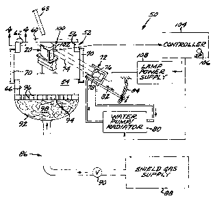
Figure 2 schematically depicts an apparatus 50 for performing welding on the
workpiece 20 at elevated temperature. The apparatus 50 includes a workpiece
housing 52 that is preferably made of a metal such as a 300-series stainless
steel.
An interior 54 of the workpiece housing 52 is sized to receive the workpiece
20
therein and to permit the use of the proper combination of exterior heating
lamps
to heat the workpiece. The workpiece housing is sized to receive three
workpieces
20 in the illustrated embodiment, see Figure 3.
As seen in the top view of Figure 3, the illustrated workpiece housing 52 is
generally rectangular. The workpiece housing 52 may have any operable shape
and size that is most suited to the processing of a particular workpiece. For
example, the workpiece housing may be hexagonal or octagonal in top view, The
workpiece housing 52 has an interior shape of its wall 56 that preferably is
curved
in the corners 58 to avoid dead gas spaces in the corners in relation to the
flow of
the shielding gas, as will be discussed subsequently. The workpiece housing 52
has a removable top cover 60, preferably made of the same material, that
provides
a welding access 62 through the open top of the workpiece housing 52 for a
welder
63 to the interior 54 of the workpiece housing 52. The top cover 60 of the
illustrated three-workpiece embodiment is preferably formed as two half-covers
that each cover half of the welding access 62, so that half of the interior 54
of the
welding housing 52 is accessible while the other half remains enclosed so as
to
retain heat in the interior 54.
As seen in Figure 4, the wall 56 preferably has heat insulation 64 on an
internal
surface 66 thereof. The heat insulation 64 aids in reducing heat loss from the
workpiece 20 and more generally from the interior 54 of the workpiece housing
52. Due to the use of the heat insulation 64, the interior of the workpiece
housing
52 and the workpiece 20 therein may be heated much more rapidly than possible
in
the absence of the heat insulation 64. The heat insulation 64 is preferably a
ceramic thermal barrier coating 68 made of a material such as yttria-
stabilized
9
CA 02452896 2003-12-11
123068
zirconia (YSZ), applied directly to the internal surface 66 or with a bond
coat
therebetween. YSZ is zirconia with typically about 2-12 weight percent,
preferably about 6-8 percent, yttria added to stabilize the zirconia against
phase
changes. The ceramic thermal barrier coating is preferably applied by air
plasma
spray (APS). The preferred ceramic thermal barrier coating 68 is at least
about
0.015 inch thick to provide sufficient insulation, but not more than about
0.030
inch thick so that the ceramic thermal barrier coating 68 does not flake and
spall
off as a result of thermal cycling the workpiece housing 52 during repeated
welding operations. Optionally but preferably, a thin layer about 0.001-0.005
inch
thick of a bond coat such as a NiCrAl material is applied to the interior
surface 66
before the ceramic thermal barrier coating 68 is applied, to aid in its
adhesion to
the interior surface 66 of the wall 56. The ceramic thermal barrier coating 68
conforms to the shape of the interior surface 66, including the curved corners
58,
providing excellent thermal insulation for the walls 56 of the workpiece
housing
52. The top cover 60 may have the ceramic thermal barrier coating 68 applied
to
its interior surface. More preferably, the flat top cover 60 is insulated on
its inner
surface with a flat ceramic tile.
The workpiece housing 52 has a window 70 therethrough. In the preferred
embodiment, there are two windows 70 on opposite sides of the workpiece
housing 52, but there may be other windows as well. The window or windows 70
are preferably made of quartz so as to be transparent to light and also to
resist the
elevated temperatures that are experienced by the workpiece housing 52. There
may be any combination of` number and size of windows 70 required to provide
heating access for particular-shaped workpieces 20. For ex.ample, there may be
windows through all of the walls 56, to heat the workpieces on all sides if
required.
Additionally, the top cover 60 may have a window therein, or the top cover may
have an opening therethrough (without a window) to provide access for a top
lamp. A virtue of the present approach, as compared with alternative heating
techniques such as resistance fumaces and induction heating, is that the
heating
CA 02452896 2003-12-11
123068
may be made very rapid but also precisely tailored for each type, shape,
configuration, and number of workpieces.
A lamp heat source 72 is located outside of the workpiece housing 52. The lamp
heat source 72 has a lamp output beam 74 directed through the window 70 (or
through the welding access) and at the workpiece 20 in the interior 54 of the
workpiece housing 52. There is preferably a lamp heat source 72 associated
with
each of the windows 70, so that in the embodiment of Figure 2 there would be
two
lamp heat sources 72, only shown directed through the right-hand window 70 and
the other (not shown) directed through the left-hand window 70. Each lamp heat
source 72 includes at least one, and preferably at least two, quartz lamps 76
(only
one of which is visible in the view of Figure 2). The quartz lamps 76 (also
termed
quartz halogen lamps) are available commercially in a 2000 watt size, so that
in
the preferred embodiment of Figure 2 there are two quartz lamps 76 associated
with each of the two lamp heat sources 72, for a total of 8000 watts of
available
heating power directed toward the workpiece 20 as the lamp output beams 74.
This high power level allows the workpiece 20 to be heated rapidly when
desired.
There may be other combinations of lamp heat sources, and in an alternative
design being developed for another type of workpiece, there is a further lamp
heat
source directed through an opening in the top cover 60. Thus, the combination
of
lamp heat sources may be precisely tailored to provide the optimum heating for
the
type of workpiece that is to be welded.
The quartz lamps 76 are preferably received in a cooled lamp housing 78. A
flow
of a coolant, preferably water, is controllably circulated through the lamp
housing
78 by a water pump/radiator 80. The illustrated form of the water cooling
structure is a closed-loop recirculating cooling system, so that external
water
source and drain connections are not required. However, a non-recirculating
water
flow system may be used as well. A flow of pressurized shop air may also be
provided to cool the bulb of the lamp 76. The cooling of the lamp housing 78
11
CA 02452896 2003-12-11
123068
cools the quartz lamp 76 and the pressurized air flow, if any, cools the lamp
bulb,
thereby prolonging the service life of the lamp 76. Additionally, a flow of
cooling
air may be provided to move heat away from the operator of the welding
facility,
and to blow or draw any fumes away from the operator.
The lamp housing 78 and thence the lamp(s) 76 are supported on a support 82.
The support 82 is preferably adjustable to establish an angle of incidence of'
each
of the lamp output beams 74 upon the workpiece 20, and also to establish a
distance of the lamp 76 from the workpiece 20. In the embodiment of Figure 2,
the lamp housing 78 and thence the lamp(s) 76 are slidably supported on the
support 82 to establish the distance of the lamp 76 from the workpiece 20, and
may be fixed in place at a selected sliding location. 'The support 82 is
pivoted at
the end closest to the workpiece housing 52, and the remote end is supported
on an
adjustable arm 84 that may be moved to cause the support 82, and thence the
lamp
housing 78 and the lamp(s) 76 to be pivoted about the pivot point to adjust
the
angle of incidence of the lamp output beam 74 onto the workpiece 20. Adjusting
the lamp(s) 76 in this manner helps to optimize the power input to, and thence
the
heating of, the workpiece or workpieces 20. Typically it is not necessary to
uniformly heat the entire workpiece 20. Instead it is sufficient that the
portion of
the workpiece 20 adjacent to the region to be welded (e.g., the tip 36 in the
illustrated embodiment) is controllably heated.
The welding operation is performed in an inert gas shielding atmosphere, such
as
an argon atmosphere, to prevent oxidation of the workpiece 20. To supply the
inert shielding gas, a controllable gas source 86 delivers a controllable flow
of the
inert shielding gas to the interior 54 of the workpiece housing 52, The gas
source
86 includes a gas supply 88 and a controllable valve 90 that meters the
shielding
gas from the gas supply 88 to the interior 54 of the workpiece housing 52.
Experience with a prototype unit has shown that the shielding gas must be
carefully introduced into the interior 54 of the workpiece housing 52 to
ensure that
12
CA 02452896 2003-12-11
123068
the entire workpiece 20, or the multiple workpieces 20 where present, are
fully
enveloped in the shielding gas. To ensure the full envelopment, the shielding
gas
is introduced through a plenum 92 that delivers the shielding gas over the
entire
area of a gas distribution plate 94 that forms the bottom of the workpiece
housing
52. The entire face of the gas distribution plate 94 has a plurality of holes
96
therethrough that spread the shielding gas over the entire bottom area of the
workpiece housing 52. A mass of steel wool 98 is placed into the plenum 92
below the gas distribution plate 94 to further diffuse the flow of the
shielding gas.
Once the shielding gas is introduced into the interior 54 of the workpiece
housing
52, the rounded corners 58 help to ensure that there are no stagnated gas
volumes
within the interior 54 of the workpiece housing 52. The shielding gas escapes
through the welding access 62 at the top of the workpiece housing 52. The flow
of
the shielding gas is desirably controlled to be of high volume and low
pressure. If
too low a flow of shielding gas is used, air may diffuse into the interior 54
of the
workpiece housing 52 and oxidize the workpiece at elevated temperature. If too
high a flow of shielding gas is used, there may be turbulence that draws air
into the
interior 54, with the same disadvantageous results.
A temperature sensor 100 senses a temperature of the workpiece 20 within the
interior 54 of the workpiece housing 52. Multiple temperature sensors 100 may
be
used for each workpiece 20 if desired, but typically a single temperature
sensor
100 for each workpiece 20 is sufficient. The temperature sensor 100 is
preferably
either a noncontacting pyrometer or, as illustrated, a contacting thermocouple
102,
or both may be used. The temperature sensor 100 provides a real-time
measurement of the temperature of the workpiece 20 in a vicinity of the region
to
be welded. The lamp heat source 72 and the welder 63, when operating, provide
the heat inputs to the workpiece 20. Heat is lost from the workpiece 20
through
the walls 56 and top cover 60 of the workpiece housing 52 by conduction,
radiation, and heating of the flow of the shielding gas, and, when the top
cover 60
13
CA 02452896 2003-12-11
123068
is removed in whole or in part, through the welding access 62. The temperature
sensor 100 provides a measurement of the actual temperature of the workpiece
20.
A feedback controller 104 has a setpoint input 106 and an input responsive to
the
temperature sensor 100. The feedback controller 104 controls the power to the
lamp heat source 72, and thence the heating power delivered to the workpiece
20
from this source, by controlling its lamp power supply 108, responsive to the
temperature of the workpiece measured by the temperature sensor 100 and to the
setpoint input 106. Although schematically illustrated as a manual control,
the
setpoint input 106 usually also includes a pre-programmed temperature profile
selected to bring the workpiece 20 to a desired welding temperature (and
perform
pre-welding heat treatments and post-welding heat treatments as desired),, and
maintain it at the welding temperature so that the welding of the workpiece 20
may
be accomplished. The feedback controller 104 also desirably has control
outputs
to the water pump/radiator 80 and to the valve 90 of the controllable gas
source 86.
These control outputs may be simple on/off controls to ensure that these
functions
are operating, or they may 'oe selected to control the magnitude of the water
flow
and gas flow, respectively.
Figure 5 illustrates a preferred form of the apparatus 50. The apparatus 50 as
described above is built into a table 110 with a control panel 112 readily
accessible
to the operator. The various elements 80, 88, 104, 108, and others (and the
interconnections, not shown in Figure 5) are built into the table 110. The
table 110
may be furnished with wheels so that it may be readily moved about. The
apparatus 50 in this form is fully self-contained except for a power input,
and
sources of air and inert gas. The air and/or inert gas sources may be provided
in
bottled form and carried on the table 110, so that only a power input is
required.
This form of the apparatus 50 thus is readily moved to convenient locations in
a
factory setting.
14
CA 02452896 2003-12-11
123068
A method for welding the workpiece 20 at elevated temperature is depicted in
block diagram form in Figure 6. The method includes furnishing the workpiece
or
workpieces 20, step 120, and furnishing the welding apparatus 50, such as that
illustrated in Figure 2 and/or Figure 5, step 122. The workpiece 20 is
preferably a
component of a gas turbine engine, such as the gas turbine blade 22
illustrated in
Figure 1. The workpiece 20 is placed into and positioned within the interior
54 of
the workpiece housing 52 so that it may be heated by the lamp output beams 74
and have its temperature sensed by the temperature sensor 100, step 124. The
workpiece 20 is supported as necessary by tooling or supports.
The gas source 86 is controllably operated to envelope the workpiece in the
shielding gas, step 126. Simultaneously, it is preferred that the water
pump/radiator 80 be operated to cool the lamp housing 78 and the lamp 76: The
operation of the controllable gas source 86 and the controllable water
pump/radiator 80 (and any air cooling systems) is preferably controlled by the
controller 104, to avoid the chance that an operator will forget to turn them
on or
have to be concerned with their proper service levels.
A heating/welding cycle is performed, step 128. In this cycle, the workpiece
20 is
heated by powering the lamp heat source 72 responsive to the setpoint input
106
and to the temperature of the workpiece 20 as measured by the temperature
sensor
100, step 130, and the workpiece 20 is welded using the welder 63, step 132.
The
heating step 130 and the welding step 132 are usually performed with both
sequential and simultaneous substeps, and Figure 7 illustrates a typical
operating
cycle. The workpiece is initially at room temperature, numeral 140, and is
initially
heated at a controllable heating rate, numeral 142. There may be an optional
pre-
welding heat treatment of the workpiece 20 prior to the step of welding,
numeral
144. A typical pre-welding heat treatment requires the workpiece 20 to be
maintained at a pre-welding temperature for a pre-welding time. The workpiece
20 is thereafter further heated at a controllable heating rate, numeral 146,
to the
CA 02452896 2003-12-11
123068
welding temperature and rnaintained at that temperature for a period of time
sufficient to perform the weld repair, numeral 148. After the welding step 132
is
complete, the workpiece 20 is cooled back to room temperature at controllable
rates, numerals 150 and 154. There may be an optional post-welding heat
treatment, numeral 152, that is performed between the cooling segments 150 and
154, typically requiring that the workpiece 20 be held at a post-welding heat-
treatment temperature for a post-welding heat-treatment period of time. The
temperature profile, including the temperatures, times, heating rates, and
cooling
rates of steps 142-154, is readily controlled by the feedback controller 104,
urith a
manual interrupt provided to allow step 148 to extend for as long a time as
required so that the welding operation may be completed. The use of the lamp
heat source 72 and the well-insulated workpiece housing 52 allow the
temperature
profile to be readily and precisely controlled. The specific parameters of the
temperature profile of Figure 7 are selected according to the specific type of
workpiece 20 and its material of construction, and are known in the art or
will be
developed for various types of workpieces.
The present approach has been reduced to practice with a prototype apparatus
50
as shown in Figure 2, and has been operated using the approach of Figure 6 and
a
temperature profile such as that shown in Figure 7.
Although a particular embodiment of the invention has been described in detail
for
purposes of illustration, various modifications and enhancements may be made
without departing from the spirit and scope of the invention. Accordingly, the
invention is not to be limited. except as by the appended claims.
16