Note: Descriptions are shown in the official language in which they were submitted.
CA 02453446 2004-O1-09
WO 03/007288 PCT/US02/22385
Title:
FEATURES TO ENHANCE DATA ENTRY
THROUGH A SMALL DATA ENTRY UNIT
Related Applications:
This PCT application claims the benefit of priority from U.S. Provisional
Patent Application No. 60/304,845, filed on July 12, 2001, entitled,
"Extendable
Microphone"; U.S. Provisional Patent Application No. 60/324,581, filed on
to September 25, 2001, entitled, "Method of Correction and Repeating of
Symbols
and Words"; U.S. Provisional Patent Application No. 60/328,002, filed on
October 9, 2001, entitled, "Method of Configuration of Symbols on a Keypad
and, Additional Features to Enhance Data Entry Through a Keypad" ; and U.S.
Provisional Patent Application No. 60/337,425, filed on December 5, 2001,
entitled, "Features to Enhance Data Entry Through a Small Data Entry Unit".
Specification:
The invention described hereafter relates to method of configuration of
2o symbols such as characters, punctuation, functions, etc. (e.g. symbols of a
computer keyboard) on a small keypad having a limited number of keys, for data
entry in general, and for data and/or text entry method combining voice/speech
CA 02453446 2004-O1-09
WO 03/007288 PCT/US02/22385
of a user and key interactions (e.g. key presses) on a keypad, in particular.
This
method facilitates the use of such a keypad.
Fig. 1, shows an example of an integrated keypad 100 for a data entry
method using key presses and voice/speeeh recognition systems. In this
example,
the keys of the keypad may respond to one or more type of interactions with
them. Said interactions may be such as:
- pressing a key with a specific finger or a portion of a finger (using a
forger
recognition system)
- a single tap (e.g. press) on a key or a double tap (e.g. two consecutive
presses
with short time interval) on a key.
- a slight pressure (or a touch) on a key, or a heavy pressure on a key
- a short time interaction with a key (e.g. a short time pressing of a key)
or a longer time pressing of a key
- etc...
To each of said interactions or to any combination of them with the keys
of the keypad, a group of symbols on said keypad may be assigned. For example,
2o the symbols shown on the top side of the keys of the keypad 100, may be
assigned to a single pressure on the keys of the keypad. If a user, for
example
presses the key 101, the symbols "DEF3 ." may be selected. In the same
example,
the symbols configured on the bottom side of the keys of the keypad 100, may
be
2
CA 02453446 2004-O1-09
WO 03/007288 PCT/US02/22385
assigned for example, to a double tap on said keys. If a user, for examples
double
taps on the key 101, then the symbols " { ~ ' " are selected.
Same selection may also be possible with other interactions such as those
described before depending on the system implemented with the keys of the
keypad. For example, a slight press (or a touch) on the key 101, could select
the
symbols configured on the top side of said key, and a heavier pressure on the
same key, could select the symbols configured on the bottom side of said key.
As described, when a user interacts with a key, a recognition system
candidates the symbols on said key which are assigned to said type of
interaction.
to For example, if a user touches or slightly presses the key 102, the system
candidates the symbols, "A", "B", "C", "2", and ",". To select one of said
candidated symbols, said user may speak, for example, either said symbol or a
position appellation of said symbol on said key. For this purpose a
voice/speech
recognition systems is used.
If the user does not speak, a predefined symbol among those candidated
symbols, may be selected as default. In this example, the punctuation ","
shown
in a box 103 is selected. To select one of the other candidated symbols, for
example the letter "B", the user may speak said letter.
In the same example, if the user presses heavily the key 102, then the
2o symbols "[", "]", and """ may be candidated. As described above, if the
user does
not speak, a predefined symbol among those selected by said pressing action,
may be selected as default. In this example, the punctuation """ is selected.
Also
in this example, to select a desired symbol among the two other candidated
CA 02453446 2004-O1-09
WO 03/007288 PCT/US02/22385
symbols "[", or "]", the user may use different methods such as speaking said
desired symbol, and/or speaking its position relating to the other symbols,
and/or
speaking its color (if each symbol has a different color), and/or any
predefined
appellation (e.g. a predefined voice or sound generated by a user) assigned to
said symbol. For example, if the user says "left", then the character "[" is
selected. If the user says "right", then the character "]" is selected.
Of course, instead of using a voice/speech, a behavior of a user combined
with a key interaction may select a symbol. For example, a user may press the
key 102 heavily and swipe his finger towards a desired symbol.
l0 The above-mentioned method of data entry may also be applied to a
keypad having keys responding to a single type of interaction with said keys
(e.g.
a standard telephone keypad having push -buttons). As shown in Fig. 2, a
keypad
200 having keys responding to a single interaction with said keys. When a user
presses a key all of the symbols on said key are candidated by the system. For
15 example, if the user presses the key 202, then the symbols, "A", "B", "C",
"2",
",", "[", " ", and "]" are canditated.
In this example, if the user does not speak, the system may select a
predefined default symbol. In this example, punctuation "," 203 is selected.
Still in the same example, to select a desired symbol among the said
20 candidates, the user may either speak a desired symbol, or for example,
speak a
position appellation of said symbol, on said key or relating to other symbols
on
i
said key, or any other appellation as described before. For example, a symbol
among those configured on the top of the key (e.g. "A", "B", "C", or "2"), may
4
CA 02453446 2004-O1-09
WO 03/007288 PCT/US02/22385
be selected by speaking it. In other hand, for example, one of the symbols
configured on the bottom side of the key, (e.g. "[", " ", or "]") may be
selected
by speaking its position relative, for example, to the two other symbols on
the
bottom side of said key, by saying for example, "left", "middle, or "right".
For
example, to select "[" 204, the user may press the key 202 and say "left".
As mentioned, the keys the keypad of fig.l, may respond to at least two
predefined types of interactions with them. Each type of interaction with a
key of
said keypad may candidate a group of said characters on said key.
As described before, during a data entry such as writing a text, different
1o interactions with the keys (e.g. one tap, double tap) and different user
behavior
(e.g. speaking, not speaking) combined with said key interactions, may be
required. Although the data entry method of this invention is a quick and easy
data entry, a good configuration of the symbols on the keys of the keypad of
this
invention, may result a still easier and quicker data entry system. This
method
will be described hereafter.
According to one embodiment, as shown in fig. 3, a number of symbols
(e.g. symbols on a computer keyboard) are physically divided into at least two
groups and arranged on a telephone keypad keys by their order of priority
(e.g.
frequency of use, familiarity of the user with existing arrangement of some
2o symbols such as letters and digits on a standard telephone keypad, etc.),
as
follow:
CA 02453446 2004-O1-09
WO 03/007288 PCT/US02/22385
First group assigned to a first type of interaction with a keys
a) A first subgroup using voice/speech
s Digits 0 - 9, and letters A-Z may be placed on the keys of a keypad
according to standard configuration and assigned to a first type of
interaction
(e.g. a first level of pressure) with said keys. A desired symbol among them
may be selected by interacting (e.g. said first type of interaction) with a
corresponding key and naturally speaking said symbol. In fig. 3 said symbols
to (e.g. 301) are configured on the top side of the keys.
Letters and digits may frequently be used during, for example, a text
entry. They
both, may naturally be spoken while, for example, tapping on corresponding
15 keys.
Therefor, for faster and easier data entry, they preferably may be assigned to
a
same
type of interaction with the keys of a keypad.
20 b) A second subgroup not using voice/speech
At least part of the other symbols (e.g. punctuation, functions, etc.) which
are frequently used during a data (e.g. text) entry may be placed on the keys
(one symbol per key) of the keypad and be assigned to said first type of
6
CA 02453446 2004-O1-09
WO 03/007288 PCT/US02/22385
interaction (e.g. a single tap) with said keys. As default, a desired symbol
may
be selected by only said interaction with corresponding key without the use of
speech/voice. In fig. 3 said symbols (e.g. 302) are configured in boxes on the
top side of the keys.
Of course, said symbols may also be selected by speaking them while
interacting with a corresponding key, but because speaking this kind of
symbols (e.g. punctuation, functions) is not always a natural behavior, it is
preferable to not to speak them.
to
At least a second group assigned to at least a second tyue of interaction with
at
least one key
At least part of the remaining symbols may be assigned to at least a
second type of interaction with said keys of said keypad. They may be divided
into two groups as
follow:
c) A third subgroup not using voice/speech
2o A third subgroup comprising the remaining frequently used symbols and
the ones which are difficult and/or not natural to pronounce, may be placed on
said keys of said keypad (one symbol per key) and assigned to a second type
of interaction (e.g. double tap, heavier pressure level, two keys pressed
7
CA 02453446 2004-O1-09
WO 03/007288 PCT/US02/22385
simultaneously, a portion of a finger by which the key is touched, etc.) with
said keys.
As default, a desired symbol may be selected by only said interaction with
a
corresponding key without the use of speech/voice. In fig. 3 said symbols
(e.g.
303)
are configured in boxes on the bottom side of the keys.
Of course, said symbols may also be selected by speaking them while
interacting with a corresponding key, but because speaking this kind of
symbols
to (e.g. punctuation,
functions) is not always a natural behavior, it is preferable to not to speak
them.
d) At least a fourth subgroup using voice/speech
A fourth subgroup comprising at least part of remaining symbols may also
be
assigned to said second type of interaction with the keys of said keypad and
be
combined with a user's behavior such as voice. In fig. 3 said symbols (e.g.
3 04) are
configured on the bottom side of the keys. Said symbols may be selected by
2o said
second type of interaction with a corresponding key and use of voice/speech in
different manners such as:
8
CA 02453446 2004-O1-09
WO 03/007288 PCT/US02/22385
- the symbols being selected by naturally pronouncing their appellation
- the symbols being selected by naturally speaking their position relative
to each
other on a key or their position while using them in a text (e.g. "<", ">"
in this
example, said symbols do not belong to said second type of interaction,
this is
only an example), by saying for example, "left, right, open, close, etc."
- the symbols which are very rarely used (they are very few) and/or are
difficult to
pronounce (e.g. 304). For a fast and easy data entry method, said
symbols may
also be selected by speaking their position on a key, or relative to each
other on
said key. Of course they be selected by using other speech such a
pronouncing
them.
e) Others
If needed, other symbols such as "F1-F12", etc. may be provided on the
keys of the keypad and assigned a type of interaction. For example, they may
be
assigned to
9
CA 02453446 2004-O1-09
WO 03/007288 PCT/US02/22385
said second type of interaction (with or without using speech), or be assigned
to
another kind of interaction such as pressing two keys simultaneously, triple
tagging on
corresponding key(s), using a switch to enter to another mode, etc.
More considerations to enhance the keynad and the use of it
Because Digits 0 - 9, and letters A-Z may be placed on the keys of a
keypad according to standard configuration and be assigned to a first type of
l0 interaction (e.g. a first level of pressure, a single tap, etc.) with said
keys
combined with speech, some keys such as 311, 312, 313, and 314, may contain at
most one symbol (e.g. digit 1 on the key 311, or digit 0 on the key 313) used
in
said configuration. Thus for better use of said keys, some easy and natural to
pronounce symbols 321-324 may be added on said keys and be assigned to said
first type of interaction. for example, a user can select the character "(" by
using a
first type of interaction with key 311 and saying, for example, "left", or
"open".
To select the character ")" the user may use the same first type of
interaction with
said key 311 and say for example, "right" or "close". This is a quick, and
more
importantly a natural speech for said symbols. Because the number of
candidated
2o symbols on said keys 311-314, assigned to said first type of interaction
does not
exceed the ones on the other keys, the voice recognition system may still have
a
similar degree of accuracy as for the other keys.
CA 02453446 2004-O1-09
WO 03/007288 PCT/US02/22385
Also, some symbols may be used in both modes (interactions with the
keys). Said symbols may be configured more than once on a keypad (e.g. either
on a single key or on different keys) and be assigned to a first and/or to a
second
type of interaction with corresponding key(s).
Fig.3, illustrates a preferred embodiment of this invention for a computer
data entry system. The keys of the keypad 300 respond to two or more different
interaction (such as different levels of pressures, single or double tap,
etc.) on
them. As shown, a number of symbols, such as alphanumerical characters,
punctuations, functions, and PC command are distributed among said keys as
1o follow:
Mode 1
First group- Letters A-Z and digits 0-9 are the symbols which are very
frequently used during a data entry such as writing a text. °They may
easily and
15 most importantly, naturally, be pronounced while pressing corresponding
keys.
Therefor they are arranged together on the same side on the keys, belonging to
a
same type of interaction (e.g. a first mode) such as a single tap (e.g. single
press)
on a key, and are selected by speaking them.
Second group- Characters such as punctuations, and functions which are
20 very frequently used during a data entry such as writing a text, may belong
to a
same type of interaction which is used for selecting said letters and digits
(e.g.
said first mode). This is to stay, as much as possible, with a same type of
interaction with the keys while entering data. Each key may only have one of
said
ii
CA 02453446 2004-O1-09
WO 03/007288 PCT/US02/22385
characters of said second group. This group of symbols may be selected by only
pressing a corresponding key, without using voice. For better distinction,
they are
shown in boxes on the top (e.g. same side as for the letters and the digits)
of the
keys. '
Mode 2
Other symbols of said number of symbols are shown on the bottom side
of the keys of the keypad. They are assigned to a second type of interaction
(e.g.
double tap) with said keys.
to
Third group- The default symbols (e.g. those which require an
interaction with a key and may not require use of voice) are shown in boxes.
Said
symbols comprise characters, punctuations, functions, etc., which are less
currently used by users.
Fourth group- Finally the symbols which are rarely used in a data entry,
and are not spelled naturally, are in this example, located at the left side
on the
bottom side of the keys. They may be selected by corresponding interaction
(e.g.
double tapping) with corresponding key and either (e.g. almost simultaneously)
2o pronouncing them, or calling them by speaking a predefined speech or voice
assigned to said symbols (e.g. "left, right", or "blue, red" etc.).
By using a keypad having keys corresponding to different type of
interaction with them (preferably two types, to not complicate the use of the
12
CA 02453446 2004-O1-09
WO 03/007288 PCT/US02/22385
keys) and having some symbols which do not require speech (e.g. defaults),
when
a key of said keypad is interacted, either a desired key is directly
interacted (e.g.
default), or the candidated symbols to be selected by a user behavior such as
voice/speech are minimal. This augments the accuracy of voice recognition
system.
For example, when a user slightly presses a key, the system selects the
symbols on the top of said key among those symbols situated on said key. If
the
user simultaneously uses a voice, then the system selects those symbols
requiring
voice among said selected symbols. This procedure of reducing the number of
to candidates and,requiring voice recognition technology to select one of
them, is
used to have a data entry with high accuracy through a keypad having a limited
number of keys. The reducing procedure is made by user natural behaviors, such
as pressing a key and/or speaking.
As shown in fig.4, the keys 41 l, 412, 413, and 414, have up to one
15 symbol (shown on the top side of said keys) requiring voice interaction and
assigned to a first type of interaction with said keys. On the other hand,
same
keys on the bottom side contain two symbols which require a second type of
interaction with said keys and also requires voice interaction. Said two
symbols
may be used more frequently (e.g. in an arithmetic data entry or when writing
a
2o software, etc.) than the other symbols belonging to same category. In this
case
and to still minimize the user errors while interacting with keys (e.g.
pressing),
said symbols may also been assigned to said first type of interaction with
said
13
CA 02453446 2004-O1-09
WO 03/007288 PCT/US02/22385
keys. The total of the candidated symbol remains low. A user may press said
key
as he desires and speak.
Additional arrangements may be provided on above-mentioned keypad to
fa~ ilitate its use by a user. For example, "-" and " " , """ and ""', or ' ;"
and ":"
ma~ be configured as default symbols on a same key 411, or on two neighboring
keys 415, 416. Also "Sp" and " " (e.g. Tab), may also be considered as default
symbols and been configured on the same key 412, each responding to a
different
type of interaction (e.g. pressing level) with said key. For example, by
pressing
once the key 412, the character "Sp" is selected. By double tapping the same
key,
to the "tab" function is selected.
While interacting with a key (e.g. pressing a key once or double tagging
on it), by not releasing said key, a symbol corresponding to said interaction
(including speech if needed) may be selected and repeated until the key is
released. For example, by double tapping on the key 415 and keeping the key
pressed after the second tap and not speaking, the default symbol (e.g. "&")
assigned to said interaction is selected and repeated until the user releases
said
key. To enter the letter "X" and repeating it, the user may for example, press
the
corresponding key 415 (without releasing it) and say "X". The letter "X" will
be
repeated until the user releases said key.
2o Also, for a more familiar look of the keypad, letters, digits, and
characters
such as "#" and "*", may be placed on said keys according to a standard
telephone keypad configuration.
14
CA 02453446 2004-O1-09
WO 03/007288 PCT/US02/22385
Additional keys separately disposed from the keys of said keypad may be
used to contain some of said symbols or additional symbols. In the example of
Fig. 6, the cursor is navigated in different directions by at least one key
separately
disposed from the keys of the keypad 600. A single key 601, may be assigned to
all directions 602. The user may, for example, press said key and say "up,
down,
t
left, or right to navigate the cursor in corresponding directions. The key
601, may
also be a mufti-directional key (e.g. similar to those used in video games, or
in
some cellular phones to navigate in the menu). The user may press on the top,
right, bottom, or left side of the key 601, to navigate the cursor
accordingly. Also
to a plurality of additional keys may be assigned, each to for example, to at
least a
symbol such as " " .
Said additional keys may be the existing keys on an electronic device. For
example, in a cellular phone, in addition to the twelve keys of a standard
telephone keypad, additional function keys such as menu key, or on/of key
etc.,
are provided. at least some of those keys may be used as additional data entry
keys, containing a number of symbols, while the system is, for example, in a
text
entry mode. This frees some spaces on the standard telephone keypad keys. The
freed spaces may permit a better accuracy of voice recognition system andlor a
more user friendly configuration of the symbols on the keys of the keypad.
The above-mentioned method of configuration and the examples shown
before are only shown as examples. Of course many other configurations of the
symbols and different assignment to different user interactions with the keys
may
CA 02453446 2004-O1-09
WO 03/007288 PCT/US02/22385
be considered. For example, a key may not have a default symbol or on a key,
there may be no symbols which are assigned to a voice/speech.
Also not all of the keys of the keypad may respond to a same kind of
interaction. For example, a first key of a keypad may respond to two levels of
pressure while another key of the same keypad may respond to a single or
double
tap on it.
Figs. 1-7 show different configurations of the symbols on the keys of
keypads.
The above-mentioned data entry system permits a full data entry such as a
full text data entry through a computer keypad. By inputting, one by one,
characters such as letters, punctuation marks, functions, etc, words, and
sentences
may be inputted.
This will have a great impact on telecommunication market permitting to
enhance many applications and methods already in use. Some of them are listed
hereafter.
It is understood that any combination of the above-mentioned interactions may
be
used for inputting a desired symbol.
According to one embodiment of the invention, the user uses voice/speech
to input a desired symbol such as a letter without other interaction such as
pressing a key. The user may use the keys of the keypad (e.g. single press,
double
press, triple press, etc) to enter symbols such as punctuations without
speaking
them.
16
CA 02453446 2004-O1-09
WO 03/007288 PCT/US02/22385
Correction and Repeating of Symbols
Different methods may be used to correct an erroneously entered symbol.
As mentioned, to enter a symbol, a user for example, may press a corresponding
key and speak said desired symbol configured ~n said key. It may happen that
the
voice/speech recognition system misinterprets the user's speech and the system
selects a non-desired symbol configured on said key.
to For example, if the user:
a) recognizes an erroneously entered symbol before entering a next
desired symbol (e.g. the cursor is positioned after said erroneous symbol,
next to it), he then may proceed a correction procedure explained
hereafter;
b) recognizes an erroneously entered symbol after entering at least a next
symbol, he first may navigate in the text by corresponding means such as
the key 101 (fig.l), or 202 (fig.2), having navigation functions, and
positions the cursor after said erroneous symbol next to it. He, then,
2o proceeds to a correction procedure explained hereafter;
After positioning the cursor after said erroneous symbol, next to it, the
user may re-speak either said desired symbol or its position appellation
without
17
CA 02453446 2004-O1-09
WO 03/007288 PCT/US02/22385
re-pressing said corresponding key. If the system again selects the same
deleted
symbol, it will automatically reject said selection and selects a symbol among
remaining symbols configured on said key, wherein either its appellation or
its
position appellation corresponds to next highest probability corresponding to
said
user's speech. If still an erroneous symbol is selected by the system, the
procedure of re-speaking the desired symbol by the user and the selection of
the
next symbol among the remaining symbols on said key with highest probability,
may continue until said desired symbol is selected by the system.
It is understood that in a data entry system using a keypad having keys
to responding, for example, two levels ofpressure, when correcting, the
recognition
system may first proceed to select a symbol among those belonging to the same
group of symbols belonging to the pressure level applied for selecting said
erroneous symbol. If none of those symbols is accepted by the user, then the
system may proceed to select a symbol among the symbols belonging to the other
pressure level on said key.
Fig. 7B, shows a flowchart corresponding to an embodiment of a method
of correction. If for any reason a user wants to correct an already entered
symbol,
he may enter this correction procedure.
Correction procedure starts at step 3000. If the replacing symbol is not
2o situated on the same key as the to-be-replaced symbol 3010, then the user
deletes
the to-be-replaced symbol 3020, and enters the replacing symbol by pressing a
corresponding key and if needed, with added speech 3030 and exits 3110.
18
CA 02453446 2004-O1-09
WO 03/007288 PCT/US02/22385
If the replacing symbol is situated on the same key as the to-be-replaced
symbol 3040, and the replacing symbol does not require speech 3050, then the
system proceeds to steps 3020 and 3030, and acts accordingly as described
before, and exits 3110.
If the replacing symbol is situated on the same key as the to-be-replaced
symbol 3040, and the replacing symbol does require speech 3060, two
possibilities are considered:
a) the cursor is not situated after the to-be-replaced symbol 3070. In this
case the user positions the cursor after the to-be-replaced symbol, next
to it 3080, and proceeds to next step 3090;
b) the cursor is situated after the to-be-replaced symbol 3070 (e.g. the
user recognizes an erroneously entered symbol, immediately). In this
case the user proceeds to next step 3090;
At the step 3090, the user speaks the desired symbol without pressing a
key. By not pressing a key and only speaking, the system understands that a
symbol belonging to a key which is situated before the cursor must be replaced
by another symbol belonging to the same key. The system then, will select a
2o symbol among the rest of the symbols (e.g. excluding the symbols already
selected) on said key with highest probability corresponding to said speech
3100.
If the new selected symbol is yet a non-desired
19
CA 02453446 2004-O1-09
WO 03/007288 PCT/US02/22385
symbol 3110, the system (and the user) re-enters at the step 3090. If the
selected
symbol is the desired one the system exits the correction procedure 3120.
Of course, instead of the above-mentioned method, a conventional
methods of correcting a symbol may also be provided. for example, to correct
an
already entered symbol, the user may simply, first delete said symbol and then
re-
enter a new symbol by pressing a corresponding lcey and if needed, with added
speech.
The text entry system, may also be applied to a word level (e.g. the user
speaks a word and types it by using a keypad). A same text entry procedure may
combine word level entry (e.g. for words contained in a data base) and
character
level entry. Therefore the correction procedure described above, may also be
applied for a word level data entry.
For example, to enter a word a user may speak said word and press the
corresponding keys. If for any reason such as disambiguity between two words
having closed pronunciation and similar key presses, the recognition system
selects a non-desired word, then the user may re-speak said desired word
without
re-pressing said corresponding keys. The system then, will select a word among
the rest of candidates words corresponding to said key presses (e.g. excluding
the
words already selected) with highest probability corresponding to said speech.
If
2o the new selected word is yet not the desired one, the user may re-speak
said word.
this procedure may be repeated until either said desired word is selected by
the
system or there is no other candidate word. in this case, the user can enter
said
CA 02453446 2004-O1-09
WO 03/007288 PCT/US02/22385
desired word by character by character entry system such as the one explained
before.
It is understood that in word level, when correcting, the cursor should be
positioned after said to-be-replaced word. For this purpose and for avoiding
the
ambiguity with character correction mode, when modifying a whole word (word
correcting level), the user may position the cursor after said to-be-replaced
word
wherein at least one space character separates said word and said cursor. This
is
because for example, if a user wants to correct the last character of an
already
entered word, he should locate the cursor immediately after said character. By
positioning the cursor after at least one space after the word (or at the
beginning
of the next line, if said word is the last word of the previous line), and
speaking
without pressing keys, the system recognizes that the user may desire to
correct
the last word before the cursor. For better result, it is understood that if
the to-be-
replaced word contains a punctuation mark (e.g. "." "?" "," etc.), the cursor
may
be replaced after an space after the punctuation mark. This is because in some
cases the user may desire to modify an erroneous punctuation mark which must
be situated at the end of a word. For this purpose the user may position the
cursor
next to said punctuation mark.
To avoid accidental corrections (e.g. the cursor is positioned somewhere
in the text and someone speaks without intending a data entry), different
methods
may be applied. For example, a pause or non-text key may be used while a user
desires for example, to rest during a text entry. Another solution is that
after the
cursor is positioned in a location in a text, after a laps of time (for
example two
21
CA 02453446 2004-O1-09
WO 03/007288 PCT/US02/22385
seconds) no correction of the last word or character before the cursor is
accepted
by the system. If a user desires to correct said word or said character he
may, for
example, navigate said cursor (at least one move to any direction) and bring
it
back to said desired position. After the cursor is repositioned in the desired
location, the time will be counted from the start and the user should start
correcting said word or said character before said laps of time is expired.
Repeating a symbol
To repeat a desired symbol, the user, first presses the corresponding key
and if required either speaks said symbol, or he speaks the position
appellation of
said symbol on its corresponding key or according to other symbols on said
key.
The system then selects the desired symbol. The user continues to press said
key
without interruption. After a predefined laps of time, the system recognizes
that
the user indents to repeat said symbol. The system repeats said symbol until
the
user stops pressing said key.
It should be noted that the above described method of correction and
repeating of key symbol can be used in conjunction with any method of entry
including but not limited to single/double tap, pressure sensitive keys, keys
pressed simultaneously, keys pressed on only a potion thereof etc.
Telephone directory
22
CA 02453446 2004-O1-09
WO 03/007288 PCT/US02/22385
To make a phone call, instead of dialing a number, a user may enter a to-
be-called destination by any information such as name (e.g. person, company,
etc.) and if necessary enter more information such as the said to-be-called
party
address, etc. A central directory, may automatically direct said call to said
destination. If there are more than one telephone lines assigned to a said
destination (e.g. party), or there are more than one choice for said desired
information entered by the user, a corresponding selection list (e.g.
telephone
numbers, or any other predefined assignments assigned to said telephone lines)
may be transmitted to the caller's phone and displayed for example, on the
to display unit of his phone. Then the user may select a desired choice and
make the
phone call.
The above-mentioned method of calling (e.g. dialing), may permit to
eliminate the need of calling a party (e.g., a person) by his/her telephone
number.
Therefor may eliminate (or at list reduces) the need of remembering phone
numbers, carrying telephone books, or using an operator's aid.
Interactive directories using voice/sueech
Voice directories are more and more used by companies, institutions, etc.
2o This method of interaction with another party is a very time consuming and
frustrating procedure for the users. Many people, by hearing a voice directory
on
the other side of the phone, disconnect the communication. Even when a person
tries to interact with said system, it frequently happens that after spending
plenty
23
CA 02453446 2004-O1-09
WO 03/007288 PCT/US02/22385
of time, the caller does not succeed to access a desired service or person.
The
main reason for this ambiguity is that when listening to a voice directory
indication, many times a user must wait until all the options are announced.
He
(the user), many times does not remember all choices which were announced. He
must re-listen to those choices.
Also many times the voice directory demands a data to be entered by a
user. This data entry is limited in variation because of either the limited
number
of keys of a telephone keypad or the complexity of entering symbols through
it.
The above-mentioned data entry method permits a fast visual interaction
l0 with a directory. The called party may transmit a visual interactive
directory to
the caller and the caller may see all choices almost instantly, and respond or
ask
questions using his telephone keypad (comprising the above-mentioned data
entry system) easily and quickly.
Voice mails
Voice mails may also be replaced by text mails. This method is already in
use. The advantage of the method of data entry described above is evident when
a
user has to answer or to write a massage to another party. The data entry
method
2o of the invention is also dramatically enhances the use of massaging systems
through mobile electronic devices such as cellular phones. One of the most
known use is in the SMS.
24
CA 02453446 2004-O1-09
WO 03/007288 PCT/US02/22385
The number of electronic devices using a telephone-type keypad is
immense. The data entry method of this invention permits a dramatically
enhanced data entry through the keypads of said devices. Of course this method
is not limited to a telephone-type keypad. It may be used for any keypad
wherein
at least a key of said keypad contains more than one symbol.
Multi-sectioned keypad
The size of a keypad using the above-mentioned data entry method, may
to still be minimized by using a keypad having multiple sections. Said keypad
may
be minimal in size (e.g. as large as the largest section, for example as large
as of
the size of an adult user's fingertip or the size of a small keypad key) in a
closed
position, and maximized as desired when the keypad is in open position
(depending on the number of sections used and/or opened).
Theoretically, in closed position, the keypad may even have the size of a
key of said keypad.
Fig 8 shows one embodiment of said keypad 800 containing at least three
sections 801, wherein each of said sections contains one column of the keys of
a
telephone keypad. When said keypad is in open position, a telephone-type
keypad
2o 800 is provided. In closed position 802 said keypad may have the width of
one of
said sections.
Another embodiment of said keypad is shown in fig. 9. Said keypad 900
contains at least two sections 901-902 wherein a first section 901 contains
two
CA 02453446 2004-O1-09
WO 03/007288 PCT/US02/22385
columns 911-912 of the keys of a telephone-type keypad, and a second section
902 of said keypad contains at least the third column 913 of said telephone-
type
keypad. When said keypad is in open position, a telephone-type keypad is
provided. Said keypad, may also have an additional column 914 of keys arranged
on said second section. In closed position 920 said keypad may have the width
of
one of said sections.
As shown in fig. 10, another embodiment of said keypad 1000 contains at
least four sections 1001-1004 wherein each of said sections contains one row
of
the keys of a telephone keypad. When said keypad is in open position, a
l0 telephone-type keypad is provided. In closed position 1005 the length of
said
keypad may the size of the width of one row of the keys of said keypad.
Fig. 11 shows another embodiment of said keypad 1100 containing at
least two sections 1101-1102 wherein a first section contains two rows of the
keys of a telephone-type keypad, and a second section of said keypad contains
15 the other two rows of said telephone-type keypad. When said keypad is in
open
position, a telephone-type keypad is provided. In closed position 1103, the
length
of the keypad may be as the size of the width of one row of the keys of said
keypad.
The above-mentioned mufti-sectioned keypad has already been described
20 in patent applications already filed by the inventor.
By using the above-mentioned data entry method through a multi-
sectioned keypad as described, a miniaturized easy to use full data entry
keypad
26
CA 02453446 2004-O1-09
WO 03/007288 PCT/US02/22385
may be provided. Such keypad may be used in many device, specially those
having a limited size.
Of course, the above-mentioned symbol configuration may be used on
said multi-sectioned keypad.
Fig. 12 shows another embodiment of a mufti-sectioned keypad 1200. The
distance between the sections having keys 1201 may be increased by any means.
For example, empty (e.g. not containing keys) sections 1202, may be provided
between the sections containing keys. This will permit more enlarged the
distance
between the sections when said keypad is in open position. In other hand, it
also
permits to have a still thinner keypad in closed position 1203.
A data entry device having integrated keypad and mouse or uoint and click
device
To enhance the data entry method through a keypad in general and
through the keypad of this invention in particular, a point and click system,
hereinafter a mouse, can be integrated in the back side of an electronic
device
having a keypad for data entry in its front side.
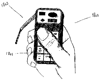
Fig. 13, shows an electronic device such a cellular phone 1300 wherein a
user holds in palm of his hand 1301. Said user may use only one hand to hold
said device 1300 in his hand and in the same time manipulate its keypad 1303
located in front, and a mouse or point and click device (not shown) located on
the
backside of said device. The thumb 1302 of said user may use the keypad 1303,
27
CA 02453446 2004-O1-09
WO 03/007288 PCT/US02/22385
while his index finger 1304 may manipulate said mouse (in the back). Three
other fingers 1305 may help holding the device in the user's hand.
The mouse or point and click device integrated in the back of said device
may have similar functionality to that of a computer mouse. Also several keys
(e.g. two keys) of either the telephone-type keypad or among the additional
keys
of said device may be assigned to the mouse click functions. for example, keys
1308 and 1318 may function with the integrated mouse of said device 1300 and
have the similar functionality of the keys of a computer mouse. Said keys may
have the same functionality as the keys of a computer mouse. For example, by
to manipulating the mouse, the user may navigate a Normal Select (pointer)
indicator 1306 on the screen 1307 of said device and position it on a desired
menu 1311. As for a computer mouse, said user then, for example, may tap
(click) or double tap (double click) on a predefined key 1308 of said keypad
(which is assigned to the mouse) to for example, select or open said desired
menu
1311which is pointed by said Normal Select (pointer) indicator 1306.
Because the display of mobile devices such as cellular phones has a small
size, a rotating button 1310 may be provided in said device to permit to a
user to,
for example rotate the menu lists. For example, after a desired menu 1311
appears on the screen 1307, a user may use the mouse to bring the Normal
Select
(pointer) indicator on said desired menu and select it by using a predefined
key
such as one of the keys 1313 of the telephone-type keypad 1303 or one of the
additional keys 1308 on said device, etc.
28
CA 02453446 2004-O1-09
WO 03/007288 PCT/US02/22385
As for a computer, then the user may press said key to open the related
menu bar 1312. To select a function 1313 of said menu bar1312, the user may
maintain said key pressed and after bringing the Normal Select (pointer)
indicator
1306 on said function, by releasing said key, said function may be selected.
Other functionalities similar to those of a computer may be provided by
using said keypad and said mouse.
Also, instead of using said keys assigned to a mouse, a user may use a
predefined voice/speech or other predefined behaviors) to replace the
functions
of said keys. For example, after positioning the Normal Select (pointer)
indicator
1306 on an icon, instead of pressing a key, the user may say "select" or
"open" to
select or open the application represented by said icon.
Fig. 14, shows an electronic device such as a mobile phone 1400. A
plurality of different icons 1411-1414 representing different applications,
are
displayed on the screen 1402 of said device. To select and/or open one of the
applications, as for computers, by using a mouse, a user may bring the a
Normal
Select (pointer) indicator 1403, on a desired icon 1411. Then said user may
select
said icon by for example pressing once, a predefined key 1404 of said keypad.
To
open the application represented by said icon, the user, for example, may
double
tap on a predefined key 1404 of said keypad.
The mouse integrated in the backside of an electronic device may be of
any type. For example, Fig.lS shows the backside of an electronic device 1500
such as the ones shown in figs. 13-14. The mouse 1501, is similar to a
conventional computer mouse. It may be manipulated, as described, with a
user's
29
CA 02453446 2004-O1-09
WO 03/007288 PCT/US02/22385
finger. It may also be manipulated like a conventional computer mouse, by
laying
the device on a surface such as a desk and swiping said mouse on said surface.
Fig. 16, shows another conventional type of mouse (a sensitive pad)
integrated on the backside of an electronic device 1500 such as the ones shown
in
figs. 13-14. The mouse 1601, is similar to a conventional computer mouse. It
may
be manipulated, as described, with a user's forger. in this example,
preferably as
described before, while holding the device in the palm of his hand, the user
uses
his index finger 1602 to use (e.g. to manipulate) said mouse. Accordingly to
this
position, the user uses his thumb (not shown) to manipulate the keys of a
keypad
(not shown) which is located in the front side (e.g. other side) of said
device.
Mobile devices should preferably, be manipulated by only one hand. This
is because while the users are in motion (e.g. being in a bus or in a train)
the users
may use the other hand for other purposes such as holding a bar while standing
in
a train or using one hand to hold a newspaper or a briefcase).
By implementing the mouse in the back of a device such as a mobile
phone, the user may manipulate said device and to enter data with one hand. He
can use simultaneously, both, the keypad and the mouse of said device.
Of course, if he desires, said user can use his both hands to manipulate
said device and its mouse.
Another method of using said device is to dispose it on a surface such as
on a desk and slide said device on said surface in a same manner as a regular
computer mouse and enter the data using said keypad.
CA 02453446 2004-O1-09
WO 03/007288 PCT/US02/22385
It is understood that the any type of mouse including the ones described
before, may be integrated in any part of a mobile device. For example, a mouse
may be located in the front side of said device. Also said mouse may be
located
on a side of said device and being manipulated simultaneously with the keypad
by fingers explained before.
It should be noted that a mouse has been used through out this discussion,
however any point and click data entry device such as stylus computer
integrated
in an electronic device and combined with a telephone-type keypad is within
the
contemplation of the present invention.
External intes~rated data entry unit
Also, an external integrated data entry unit comprising a keypad and
mouse may be provided and used in electronic devices requiring data entry
means such as keyboard (or keypad) andlor mouse. There may be provided an
integrated data entry unit having the keys of a keypad (e.g. a telephone-type
keypad) in front of said unit and a mouse being integrated within the back of
said
unit. Said data entry unit may be connected to a desired device such as a
computer, a PDA, a camera, a TV, a fax machine, etc.
Figs. 19 shows a computer 1900 comprising a keyboard 1901, a mouse
1902, a monitor 1903 and other computer accessories (not shown). In some
circumstances (e.g. when a user does not desire to sit down on a desk chair in
front of a monitor and he prefers, for example, to lie down on his bed while
31
CA 02453446 2004-O1-09
WO 03/007288 PCT/US02/22385
interacting with said computer) instead of a large keyboard and/or
corresponding
mouse a user may utilize a small external integrated data entry unit. There
may
be provided an external data entry unit 1904 containing features such as
keypad
keys 1911 positioned on the front side of said data entry unit, a microphone
which may be an extendable microphone 1906, a mouse (not shown) integrated
within the back side of said data entry unit (described before). Said data
entry
unit may be (wirelessly or by wires) connected to said electronic device (e.g.
said
computer 1900). An integrated data entry system such as the one described
before
(e.g. using voice recognition systems combined with interaction of keys by a
l0 user) may be integrated either within the said electronic device (e.g. said
computer 1900) or within said data entry unit 1904. Also a microphone may be
integrated within said electronic device (e.g. computer). Said integrated data
entry system may use one or both microphones located on said data entry unit
or
within said electronic device.(e.g. computer).
For a better view of while interacting, specially when interacting from far
with an electronic device such as said computer 1900, a display unit 1905 may
be
integrated within said a entry unit such as said integrated data entry unit
1904 of
this invention. When interacting from far with a monitor 1903 of said
electronic
device 1900, a user may have a general view of the display 1910 of said
monitor
1903. A closed area 1908 around the arrow 1909 or another area selected by
using the mouse on the display 1910 of said monitor 1903 may simultaneously be
shown on said display 1905 of said data entry unit 1904. The size of said area
1908 may be defined by manufacturer or by the user. Preferably the size of
said
32
CA 02453446 2004-O1-09
WO 03/007288 PCT/US02/22385
area 1908 may be closed to the size of the display 1905 of said data entry
unit
1904. This may permit a closed and/or if desired a real size view of the
interacting area 1908 to the user (e.g. by seeing said area on the data entry
screen
1905). While having a general view of the display 1910 of the monitor 1903, a
user may have a particular closed view of the interacting area 1908 which is
simultaneously shown on the display 1905 of said data entry unit 1904. For
example a user may use the keypad mouse (not shown, in the back of he keypad)
to navigate the arrow 1909 on the computer display 1910. Simultaneously said
arrow 1909 and the area 1908 around said arrow 1909 on said computer display
l0 1910 may be shown on the keypad display 1905.
For an interaction such as opening a file, a user may for example, navigate
an arrow 1909 on a the screen 1910 of said computer an position it on a
desired
file 1907. Said navigated areas 1908 and said file 1907 may be seen on said
data
entry screen 1905. By having the display 1905 of said data entry unit 1904
closed
15 to his eyes, a user can clearly see his interactions on the display 1905 of
said data
entry unit 1904 while having a general view on a large display 1910 of said
electronic device 1900 (e.g. computer).
It is understood that said interaction area 1908 may be defined and vary
according to different needs or definitions. For example, said interacting
area
2o may be the area around an arrow 1909 wherein said arrow is in the center of
said
area or said area is the area at the right, left, top, bottom , etc. of said
arrow or any
area on the screen of said monitor, regardless of the location of said arrow
on the
display of said monitor).
33
CA 02453446 2004-O1-09
WO 03/007288 PCT/US02/22385
Fig. 20 shows a data entry unit 2000 such as the one described before
being connected to a computer 2001. During a data entry such as a text entry,
the
area 2002 around the interacting point 2003 (e.g. cursor) is simultaneously
shown
on the keypad display 2004.
Figs. 21a-21b show an example of different electronic devices which may
use the above described data entry unit. Fig. 21 a shows a computer 2100 and
fig.
21b shows a TV 2101. The data entry unit 2102 of said TV 2101 may also
operate as a remote control of said TV 2101. For example, by using the mouse
(not shown) situated in the back side of said data entry unit 2102, a user may
to locate a selecting arrow 2103 on the icon 2104 representing a movie or a
channel
and opening it by double tapping (double clicking) on a key 2105 of said data
entry unit. Of course said data entry unit 2102 of said TV may also be used
for
data entry such as Internet through TVs or sending massages through TVs, cable
TVs, etc. In this case the integrated data entry system of this invention may
be
15 integrated within for example, the TV's modem 2106.
Extendable Microphone
An extendable and /or rotatable microphone may be integrated in
2o electronic devices such as cellular phones. Said microphone may be a rigid
microphone being extended towards a user's mouth.
With the advancement of the technology, new input systems and devices
are coming to the market to permit easy interacting with instruments. Many of
those input systems use voice/speech recognition system wherein a user speaks
34
CA 02453446 2004-O1-09
WO 03/007288 PCT/US02/22385
the data or commands to be input. Because it is a natural way to input data,
voice
recognition system is becoming very popular. Computers, telephones, toys, and
many other instruments are equipped with this different kinds of data entry
system using voice recognition systems.
Although this is a good method of input, it has an important shortcoming.
It is not a discrete method of input. A user, usually, does not want others to
hear
what he speaks, and in the other hand people do not like other people's loud
speaking.
To overcome (or at least reduce) significantly this problem, the user must
speak quietly. To not cause misinterpretation of user's voice/speech by a
voice
recognition system, the microphone must be closed to user's mouth.
It is the subject of this invention to provide instruments using a user's
voice as data, with a microphone extending from said instruments towards the
user's mouth.
There are many advantages using such a microphone. One advantage of
such a microphone is that by extending said microphone towards said user's
mouth and speaking closed into it the voice/speech recognition system may
better
distinguish and recognize said voice/speech. Another advantage is that by
positioning said microphone close to user's mouth (e.g. next to the mouth), a
user
may speak silently (e.g. whisper) into it. This permits an almost silent and a
discrete data entry. Still, another advantage of said microphone is that
because of
being integrated in corresponding electronic device, in order to keep said
microphone in a desired position (e.g. close to a user's mouth), a user may
not
CA 02453446 2004-O1-09
WO 03/007288 PCT/US02/22385
have to hold said microphone by his hand(s). Also, said user does not have to
carry said microphone separately from said electronic device.
By combining the features such as the enhanced keypad of the invention,
the mouse, the extendable microphone and the data entry method in a manner
such as the manners explained before, either in an electronic device or as an
external unit to be connected to an electronic device, a completely enhanced
data
entry system may be provided. A user, may for example, by only using one hand,
hold an electronic device such as a data entry device (e.g. mobile phone, PDA,
et.), use all of the features such as the enhanced keypad, integrated mouse,
and
to the extendable microphone, etc., and in the same time by using his natural
habitudes (e.g. pressing keys of the keypad and in needed, speaking) provide a
quick, easy, and specially natural data entry.
One of the most important applications of the extendable microphone is
when the data entry systems of mobile communication devices combine use of
keypad and voice/speech recognition system. In this method a user interacts
with
a key (for example by pushing it), and in the same time he may speak for
example, a symbol on said key. In order to press a key containing a desired
symbol, the user may need to see the keypad. He also may need to see the data
on
a display of the device. In the other hand, the user may prefer to speak said
2o symbols quietly. The extendable microphone permits to position the mobile
phone far from eyes, enough to see that keypad, and in the same time to have
the
microphone closed to the mouth, permitting to speak quietly.
36
CA 02453446 2004-O1-09
WO 03/007288 PCT/US02/22385
As they many people are used to, they may hold their mobile phone in one
hand, while pressing the keys of the keypad with a thumb of the same hand. The
second hand may be used to either hold said hand around the microphone to
reduce the outside noise, or to keep the microphone in an optimal relationship
with the mouth.
If the microphone of an instrument is wireless, or the member connecting
it with the instrument is made from non-rigid materials, the user may hold the
microphone in a manner to position it at the palm side of his hand, between
two
fingers. Then by positioning the palm o said hand around the mouth he can
significantly reduce the outside noise while speaking.
It is understood that the user interface containing the data entry unit and
the display, of an electronic device using a user's voice to input data, may
be of
any kind. For example, instead of a keypad it may contain a touch sensitive
pad,
or it may be equipped only with a voice recognition system without the need of
a
keypad.
Fig. 18, shows according to one embodiment of the invention, an
electronic device 1800 such as a cellular phone or a PISA. As shown, the
keypad
1801 is located in the front side of said device 1800. A mouse (not shown) is
located in the backside of said device 1800, An extendable microphone 1802 is
also integrated within said device. Said microphone may be extended and
positioned in a desired position (e.g. next to the user's mouth) by a user.
Said
device may also contain a data entry method as described before. By using only
one hand, a user may proceed to a quick and easy data entry with a very high
37
CA 02453446 2004-O1-09
WO 03/007288 PCT/US02/22385
accuracy. Positioning said microphone next to user's mouth, permits a better
recognition of the voice/speech of the user by the system. Said user, may also
speak silently (e.g. whisper) into said microphone. This permits an almost
silent
data entry.
In alternative embodiments of the present invention Figs.18b to 18c, show
a mobile phone 1800 having a keypad 1801 and a display unit. The mobile phone
is equipped with a pivoting section 1803 with a microphone 1802 installed at
its
end. By extending the microphone towards his mouth, the user may speak quietly
into the phone and in the same time being capable to see the display and
keypad
1801 of his phone and eventually use them simultaneously while speaking to
microphone 1802.
Fig. 18d, shows a rotating extendable microphone 1810 to permit a user to
position the instrument at a convenient relationship to him, and in the same
time
by rotating and extending the microphone accordingly, to bring microphone 1810
close to his mouth or to a desired location. It must be noted that the member
connecting the microphone to the instrument may have at least two sections,
being extended/retracted according to each other and to the instrument. They
may
have folding, sliding, telescopically and other movement for extending or
retracting.
Figs. 18e and 18f, shows an integrated rotating microphone 1820 being
telescopically extendable. In this embodiment, the extendable section
comprising
microphone 1820 may be located in the instrument. When desired, a user may
38
CA 02453446 2004-O1-09
WO 03/007288 PCT/US02/22385
pull this section out and extend it towards his mouth. Microphone 1820 may
also
be used, when it not pulled out.
According to another embodiment of the invention as shown in Figs. 18g
and 18h, the extending member 1830 containing a microphone 1831, may be a
section of a mufti-sectioned device. This section may be used as the cover of
said
device. The section comprising the microphone 183 lmay itself been multi-
sectioned to be extendable and/or adjustable as desired.
According to embodiment shown in Fig. 18i, an extendable microphone
1840 as described before, may be installed in a computer or similar devices.
to Also, according to another embodiment of the invention, a microphone of
an instrument may be attached to a user's ring, or itself being shaped like a
ring,
and be worn by said user. This microphone may be connected to said instrument,
either wirelessly or by wire. When in use, the user approaches his hand to his
mouth and speaks.
It is understood that instruments shown in the drawings are shown as
example. The extendable microphone may be installed in any instrument. It may
also be installed at any location on extending section.
In communication devices, the extending section comprising the
microphone may be used as the antenna of said instruments. In this case the
antennas may be manufactured as sections described, and contain integrated
microphones.
It must be noted that in addition to at least an extendable microphone, an
instrument may comprise at least one additional regular microphone, wherein
39
CA 02453446 2004-O1-09
WO 03/007288 PCT/US02/22385
said microphones may be used separately or simultaneously with said extendable
microphone.
It must be noted that the extendable member comprising the microphone
may be manufactured with rigid materials to permit positioning the microphone
in a desired position without the need of keeping it by hand.
For better manipulation, the section, comprising the microphone may also be
manufactured by semi rigid or soft materials.
It must be noted that any extending/retracting methods such as
unfolding/folding methods may be used.
to As described before, the integrated keypad and/or the mouse and/or the
extendable microphone of this invention may also be integrated within a
variety
of electronic devices such as a PDA, a remote control of a TV, and a large
variety
of other electronic devices. For example, by using said integrated keypad and
mouse within remote control of a TV, a user may point on an icon, shown on the
TV screen relating to a movie and select said movie by using a predefined key
of
said remote control.
Also, as described, said integrated keypad and/or mouse and/or
extendable microphone may be manufactured as a separated device and to be
connected to said electronic devices.
2o Of course said keypad, alone or integrated with said mouse and/ or said
extendable microphone, may be combined with a data and text entry method such
as the data entry method of this invention.
CA 02453446 2004-O1-09
WO 03/007288 PCT/US02/22385
Fig. 17 shows some of the electronic devices which may use the enhanced
keypad, the enhanced mouse, the extendable microphone, and the data entry
method of this invention.
An electronic device may contain at least one or more of the features of
this invention. It may, for example, contain all of the features of the
invention as
described.
Data entry through a land line phone
to The data entry method described before, may also be used in land-lined
phones and their corresponding networks. As known, each key of a telephone
keypad generates a predefined tone which is transmitted through the land line
networks. There are twelve predefined tones assigned to twelve keys of
telephone
keypads. By using, a land line telephone and its keypad, for the purpose of a
data
entry such as entering text, there may be the need of additional tones to be
generated. To each symbol, there may be assigned a different tone so that the
network will recognize a symbol according to the generated tone assigned to
said
symbol.
A wrist-worn mufti-sectioned data entry unit
Fig. 22a shows as example, different embodiments of a data entry units
2201-2203 of this invention as described before. To reduce the size of said
data
41
CA 02453446 2004-O1-09
WO 03/007288 PCT/US02/22385
entry unit a mufti-sectioned data entry unit 2202-2203 which may have a multi-
sectioned keypad 2212-2222 as described before, may be provided. said multi-
sectioned data entry unit may have some or all of the features of this
inventions.
It may also have an integrated data entry system described in this
application. As
example, the data entry unit 2202 comprises a display 2213 an antenna 2214
(may be extendable), a microphone 2215 (may be extendable), a mouse
integrated in the beck of said data entry unit (not shown).
An embodiment of a data entry unit of this invention may be carried on a
wrist. It may be integrated within a wrist worn device such as a watch or
within a
1'o bracelet such as a wristwatch band. Said data entry unit may have some or
all of
the features of the integrated data entry unit of this invention. This will
permit to
have a small data entry unit attached to a user's wrist. Said wrist-worn data
entry
unit may be used as a data entry unit of any electronic device. By connecting
his
wrist-worn data entry unit to a desired electronic device, a user for example,
may
open his apartment door, interact with. a TV, interact with a computer, dial a
telephone number, etc.. A same data entry unit may be used for operating
' different electronic devices. For this purpose, an access code may be
assigned to
each electronic device. By entering (for example, through said data entry
unit) the
access code of a desired electronic device a connection between said data
entry
2o unit and said electronic device may be established.
Fig. 22b shows an example of a wrist-worn data entry unit 2290 (e.g.
mufti-sectioned data entry unit having a mufti-sectioned keypad 2291) of this
invention (in open position) connected (wirelessly or through wires 2292) to a
42
CA 02453446 2004-O1-09
WO 03/007288 PCT/US02/22385
hand-held device such as a PISA 2293. Said multi-sectioned data entry unit
2290
may also comprise additional features such as some or all of the features
described in this application. In this example, there are provided a display
unit
2294 an antenna 2295, a microphone 2296 and a mouse 2297.
It is understood that said multi-sectioned keypad may be detached from
the wrist worn device/bracelet 2298. For this purpose different
detachment/attachment known to people skill in the art may be provided. For
example, as shown in fig. 23a, a housing 2301 for containing said data entry
device may be provided within a bracelet 2202. Fig. 23b shows said housing
l0 2303 in open position. A detachable data entry unit 2304 may be provided
within
said housing 2301. Fig 23c shows said housing in open position 2305 and in
close
position 2306. In open position (e.g. when using said data entry unit), part
of the
elements 2311 (e.g. part of the keys and/or display, etc) of said data entry
unit
may lye down within the cover 2312 of said housing.
15 According to one embodiment of the invention, a device such as a
wristwatch 2307 may be provided in the opposite side on the wrist within the
''
same bracelet. For example, there may be provided a wristwatch band having a
housing to contain a data entry unit. Said wristwatch band may be attached to
any
wrist device such as a wristwatch, a wrist camera, etc. The housing of the
data
2o entry device may be located on one side 2308 of a wearer's wrist and the
housing
of said other wrist device may be located on the opposite side 2309 of said
wearer's wrist. To attach said wristband to a device such as a wristwatch the
traditional wristwatch band attachment means 2310 (e.g. bars) may be provided.
43
CA 02453446 2004-O1-09
WO 03/007288 PCT/US02/22385
The above mentioned wristband housing may also be used to contain any
other wrist device. for example, instead of containing a data entry unit, said
wrist
housing may be adapted to contain a variety of electronic devices such as a
wristphone.
There may be a lot of advantages when using a wrist-worn data entry unit
of this invention. for example, a user may carry an electronic device in for
example, his pocket, and having a display unit (may be flexible) of said
electronic
device in his hand. The interaction with said electronic device may be
provided
through said wrist-worn data entry unit. In another example, the wrist-worn
data
entry unit of this invention may be used to operate an electronic news display
(a
PCT application regarding an electronic news display has been filed on October
27tn, 2000 by the inventor).
Extendable Display Unit
According to one embodiment of the invention an extendable display unit
may be provided within an electronic device such as data entry unit of the
invention or within a mobile phone. Fig. 24a shows an extendable display unit
2400 in closed position. This display unit may be made of rigid and/or semi
rigid
materials and may be folded or unfolded for example by corresponding hinges
2401, or being telescopically extended or retracted, or having means to permit
it
being expanded and being retracted by any method.
44
CA 02453446 2004-O1-09
WO 03/007288 PCT/US02/22385
Fig 24b shows a mobile computing device 2402 such as a mobile phone
having said extendable display 2400 of this invention, in open position, When
open, said extended display unit may have the width of an A4 standard paper
permitting the user to see and work on a real width size of a document while,
for
example, said user in writing a letter with a word processing program or
browsing a web page.
The display unit of the invention may also be made from flexible
materials. Fig 25a shows a flexible display unit 2500 in closed position.
It is understood that the display unit of the invention may also display the
information on at least part of it's other (e.g. exterior} side 2505. This is
important because in some situations a user may desire to use the display unit
without expanding it.
Fig. 25b shows an electronic device 2501 having a flexible display unit
2500 of the invention, in open position.
By having an electronic device such as the data entry unit of the
invention, a mobile phone, a PDA, etc., having at least one of the enhanced
features of the invention such as an extendable/non extendable display unit
comprising a telecommunication means as described before, a mouse of the
invention, an extendable microphone, an extendable camera, a data entry system
~ of the invention, a voice recognition system, or any other feature described
in this
application, a complete data entry/computing device, which may be held and
manipulated by one user's hand, may be provided. This is very important
because
CA 02453446 2004-O1-09
WO 03/007288 PCT/US02/22385
as is well known that in mobile environment computing/data entry at least one
of
the user's hand must be free.
Extendable Camera
As described for extendable microphone, an electronic device may also be
equipped with an extendable camera. For example, for the data entry system of
the invention combining keys presses and lip reading (instead or in addition
to
voice/speech of the user) an extendable camera may be provided in
corresponding electronic device or data entry unit..
Fig.26 shows a mobile computing device 2600 equipped with a pivoting
section 2601. Said pivoting section may have a camera 2602 and/or a microphone
2603 installed at, for example, its end. By extending the camera towards his
mouth, the user may speak to the camera and the camera may transmit images of
the user's lips for example, during data entry of the invention using
combination
of key presses and lips. The user, in the same time may be capable to see the
display and the keypad of his phone and eventually use them simultaneously
while speaking to the camera. Of course the microphone installed on the
extendable section may transmit the user's voice to the voice recognition
system
of the data entry system.
The extendable section 2601 may contain an antenna, or itself being the
antenna of the electronic device.
46
CA 02453446 2004-O1-09
WO 03/007288 PCT/US02/22385
The data entry method of this invention may also use other data entry
means. For example, instead of assigning the symbols to the keys of a keypad,
said symbols may be assigned to other objects such as the fingers (or portions
of
the fingers) of a user. Also instead of (or in addition to) voice/speech
input, the
system may recognize the data input by reading (recognizing the movements of)
the lips of the user in combination with/without key presses. The user may
press
a key of the keypad and speak a desired letter among the symbols on said key.
By
recognizing the movements of the user's lips speaking said letter combined
with
said key press, the system may easily recognize and input the intended letter.
Also as mentioned, example given in method of configuration described
in this application were showed as samples. Variety of different
configurations
and assignment of symbols may be considered depending on data entry unit
needed. The principle in this the method of configuration is to define
different
group of symbols according to different factors such as frequency of use,
natural
pronunciation, natural non-pronunciation, etc, and assign them accordingly
assigning them priority rates. The highest priority rated group (with or
without
speaking ) is assigned to easiest and most natural key interaction (e.g. a
single
press). This group also includes the highest ranked non-spoken symbols. Then
the
second highest priority is assigned to second less easier interaction (e.g.
double
2o press) and so on.
Thus, while there have been shown and described and pointed out
fundamental novel features of the invention as applied to alternative
embodiments thereof, it will be understood that various omissions and
47
CA 02453446 2004-O1-09
WO 03/007288 PCT/US02/22385
substitutions and changes in the form and details of the disclosed invention
may
be made by those skilled in the art without departing from the spirit of the
invention. It is to be understood that the drawings are not necessarily drawn
to
scale, but that they are merely conceptual in nature. For example, instead of
providing a separate pressure system to each key of a keypad, a single
pressure
sensitive system (e.g. a pressure sensitive pad) may be provided with all of
them
(e.g. a single large pad above or under the keys). Also a user may interact
with a
key by other means than his fingers. For example, said user may use a pen to
press a key.
48