Note: Descriptions are shown in the official language in which they were submitted.
CA 02453472 2003-12-17 =
SLAT CARRIER
BACKGROUND OF THE INVENTION
Field of the Invention
The present invention relates to load transporting devices and
more particularly pertains to a new slat carrier for facilitating
transportation of slats to be used in an animal pen.
Description of the Prior Art
The use of load transporting devices is known in the prior art.
U.S. Patent No. 3,529,736 describes a device for raising loads to
allow for handling of the load. Another type of load transporting
device is U.S. Patent No. 5,441,379 having a hand cart for
facilitating transportation and erecting of wall panels. U.S. Patent
No. 5,988,659 has a device for lifting and transporting panels. U.S.
Patent No. 3,795,336 has an apparatus coupled to a vehicle for
lifting and transporting a building module. U.S. Patent No.
6,270,299 has a system for securing a load of material during
storage in transit. U.S. Patent No.1,239,771 has a truck that is
positioned under a chicken coop and raised to lift the chicken coop
and allow the chicken coop to be transported to a desired location.
U.S. Patent No. 5,697,309 has a apparatus for supporting a mattress
and manipulating the mattress as is being sewn. U.S. Patent No.
5,464,315 has an apparatus for compressing and lifting objects to
facilitate transporting of the objects. U.S. Patent No. 3,346,131
1
CA 02453472 2003-12-17
has a trailer having wheel assemblies that are vertically
positionable to allow the for the trailer to be more conveniently
loaded by a user. U.S. Patent No. 3,410,431 has a clamp
mechanism that is coupled to a forklift to allow the forklift handle
materials not positioned on a pallet. U.S. Patent No. 3,815,768 has
a trailer for hauling wall panels or palletized loads. U.S. Patent
No. 4,626,017 has a trailer structure designed to transport sheets of
glass or other frangible materials safely without damage to the
materials. U.S. Patent No. 4,699,558 has a cargo loader that is
design for being positioned around a desired cargo and can lift the
cargo.
While these devices fulfill their respective, particular
objectives and requirements, the need remains for a device that has
certain improved features for lifting and manipulating a slat for an
animal pen. SUMMARY OF THE INVENTION
The present invention meets the needs presented above by a
support assembly rotated coupled to a mounting assembly to allow
the slat coupled to the support assembly to be rotated to a desired
position.
Still yet another object of the present invention is to provide
a new slat carrier that allows the slat to rotated from a horizontal
position to a vertical position to fit through doorways and thereby
allow new slats to be transported into existing animal pens.
Even still another object of the present invention is to
provide a new slat carrier that has the wheel assembly pivotally
2
CA 02453472 2006-05-24
coupled to the mounting assembly to allow the slat coupled to the
support assembly to be deposited on the floor of the animal pen.
To this end, the present invention generally comprises a
support assembly being designed for selectively receiving the slat
to be transported. A mounting assembly is rotatably coupled to the
support assembly. The support assembly is rotated with respect to
the mounting assembly whereby the support assembly is designed
for rotating the slat from a horizontal position to a vertical position
to facilitate transportation of the slat through doorways. The
mounting assembly is designed for being selectively coupled to a
vehicle whereby the mounting assembly permits the vehicle to
transport the slat supported by the support assembly. A wheel
assembly is coupled to the mounting assembly. The wheel assembly
is designed for engaging a support surface whereby the wheel
assembly facilitates transportation of the support assembly across
the support surface.
There has thus been outlined, rather broadly, the more
important features of the invention in order that the detailed
description thereof that follows may be better understood, and in
order that the present contribution to the art may be better
appreciated. There are additional features of the invention that
will be described hereinafter and which will form the subject matter
of the claims appended hereto.
3
CA 02453472 2006-05-24
In one aspect, the invention provides a slat carrier for facilitating
transporting a slat used in an animal pen, the slat carrier comprising a
support
assembly being adapted for selectively receiving the slat to be transported, a
mounting assembly being rotatably coupled to the support assembly, the support
assembly being rotated with respect to the mounting assembly such that the
support
assembly is adapted for rotating the slat from a horizontal position to a
vertical
position, the mounting assembly being adapted for being selectively coupled to
a
vehicle such that the mounting assembly permits the vehicle to transport the
slat
supported by the support assembly, and a wheel assembly being coupled to the
mounting assembly, the wheel assembly being adapted for engaging a support
surface such that the wheel assembly facilitates transportation of the support
assembly across the support surface.
In one aspect, the invention provides a slat carrier for facilitating
transporting a slat used in an animal pen, the slat carrier comprising a
support
assembly being adapted for selectively receiving the slat to be transported, a
mounting assembly being rotatably coupled to the support assembly, the support
assembly being rotated with respect to the mounting assembly such that the
support
assembly is adapted for rotating the slat from a horizontal position to a
vertical
position, the mounting assembly being adapted for being selectively coupled to
a
vehicle such that the mounting assembly permits the vehicle to transport the
slat
supported by the support assembly, a wheel assembly being coupled to the
mounting
assembly, the wheel assembly being adapted for engaging a support surface such
that the wheel assembly facilitates transportation of the support assembly
across the
support surface, the support assembly comprising a frame member and a pivot
member, the frame member being coupled to the pivot member such that the frame
member is adapted for supporting the weight of the slat, the pivot member
being
positioned around a portion of the mounting assembly such that the pivot
member
selectively rotates around the mounting assembly to allow the slat to be
selectively
pivoted between the horizontal position and the vertical position, the support
assembly comprising a securing assembly, the securing assembly being
operationally coupled to the frame member, the securing assembly being adapted
for
engaging the slat such that the securing assembly is for securing the slat to
the
3a
CA 02453472 2006-05-24
frame member, the securing assembly of the support assembly comprising a
plurality of armature members, each of the armature members being pivotally
coupled to the frame member, each of the armature members being adapted for
being selectively pivoted over the slat to secure the slat between the
armature
members and the frame member to secure the slat member to the frame member
when the slat is positioned adjacent the frame member, each of the armature
members comprising a pivot portion and an extension portion, the pivot portion
of
each of the armature members being pivotally coupled to the frame member, the
extension portion being coupled to the pivot portion of the associated one of
the
armature members opposite the frame assembly, the extension portion of each of
the
armature members being adapted for being selectively extended over the slat to
secure the slat to the frame member when the pivot portion of the associated
one of
the armature members is pivoted with respect to the frame member, the securing
assembly comprising a handle member, the handle member being pivotally coupled
to the frame member, the handle member being operationally coupled to the
armature members such that pivoting of the handle member in a first direction
pivots each of the armature members with respect to the frame member to secure
the
slat to the frame member, the handle member being pivotal in a second
direction to
pivot the armature members with respect to the frame member to allow the slat
to be
removed from the frame member, a motor member being coupled to the mounting
assembly, the motor member being operationally coupled to the support assembly
such that the motor member rotates the support assembly with respect to the
mounting assembly to rotate the slat between the horizontal position and the
vertical
position when the motor member is actuated by the user, a first gear member
being
coupled to the motor member such that the first gear member is selectively
rotated
by the motor member, a second gear member being coupled to the pivot member of
the support assembly, the first gear member being operationally coupled to the
second member such that the second gear member is rotated by the first gear
member to rotate the support assembly with respect to the mounting assembly
when
the first gear member is rotated by the motor member, the mounting assembly
comprising a main member, the pivot member of the support assembly being
rotationally coupled to the main member of the mounting assembly, the main
member being adapted for being selectively coupled to the vehicle such that
the
3b
CA 02453472 2006-05-24
main member is for supporting the weight of the slat when the slat is being
transported by the vehicle, the mounting assembly comprising a mounting plate,
the
mounting plate being coupled to the main member such that the mounting plate
is
positioned opposite the wheel assembly, the mounting plate being adapted for
being
coupled to the vehicle such that the mounting plate secures the main member to
the
vehicle, the mounting assembly comprising a sleeve portion, the sleeve portion
being coupled to the mounting plate, the sleeve portion being adapted for,
being
operationally coupled to the vehicle such that the sleeve portion permits the
mounting assembly to maintain a substantially parallel orientation with the
support
surface when the mounting assembly is raised and lowered by the vehicle, the
mounting assembly comprising a plurality of bracing members, each of the
bracing
members extending between the main member and the mounting plate of the
mounting assembly such that the bracing members are for bracing the main
member
when the main member is supporting the weight of the slat, the wheel assembly
comprising an arm member and a pair of wheels, the wheels being rotatably
coupled
to the arm member such that the wheels are adapted for rolling across the
support
surface, the arm member being pivotally coupled to the main member of the
mounting assembly such that the arm member changes angle with respect to the
main member of the mounting assembly to maintain contact between the wheels
and
the support surface when the vehicle raises and lowers the mounting assembly,
the
arm member comprising a tongue portion and a stabilizing portion, the tongue
portion being pivotally coupled to the main member of the mounting assembly,
the
stabilizing portion being coupled to the tongue portion such that the
stabilizing
portion is positioned opposite the mounting assembly, the wheels being
rotatably
coupled to the stabilizing portion such that the wheels are positioned in a
spaced
relationship to inhibit tipping of the support assembly, the mounting assembly
and
the wheel assembly when in use, and a biasing member being coupled to the main
member of the mounting assembly and the arm member of the wheel assembly, the
biasing member biasing the arm member of the wheel assembly away from the
mounting assembly such that the biasing member is for biasing the wheels
against
the support surface when the mounting assembly is being raised and lowered by
the
vehicle.
3c
CA 02453472 2007-05-04
In one aspect, the invention provides a slat carrier for facilitating
transporting a slat used in an animal pen, the slat carrier comprising a
support
assembly configured to selectively receive the slat to be transported, a
mounting
assembly being rotatably coupled to the support assembly, the support assembly
being rotatable with respect to the mounting assembly such that the support
assembly is capable of rotating the slat from a substantially horizontal
orientation to
a substantially vertical orientation, and a wheel assembly coupled to the
mounting
assembly, the wheel assembly being configured to at least partially support
the
mounting assembly on a support surface and permit movement of the mounting
assembly across the support surface with the slat in the substantially
vertical
orientation.
In another aspect, the invention provides a slat carrier for facilitating
transporting a slat used in an animal pen, the slat carrier comprising:
a support assembly being adapted for selectively receiving the slat to be
transported;
a mounting assembly being rotatably coupled to said support assembly, said
support
assembly being rotated with respect to said mounting assembly such that said
support
assembly is adapted for rotating the slat from a horizontal position to a
vertical position
said mounting assembly being adapted for being selectively coupled to a
vehicle such
that said mounting assembly permits the vehicle to transport the slat
supported by said
support assembly; and
a wheel assembly being coupled to said mounting assembly, said wheel assembly
being
adapted for engaging a support surface such that said wheel assembly
facilitates
transportation of said support assembly across the support surface;
wherein said wheel assembly comprises an arm member and at least one wheel,
said
wheel being rotatably coupled to said arm member such that said wheel is
adapted for
rolling across the support surface, said arm member being pivotally coupled to
said
mounting assembly such that said arm member changes angle with respect to said
mounting assembly to maintain contact between said wheel and the support
surface when
the vehicle raises and lowers said mounting assembly.
In another aspect, the invention provides a slat carrier for facilitating
transporting a slat used in an animal pen, the slat carrier comprising:
3d
CA 02453472 2007-05-04
a support assembly being adapted for selectively receiving the slat to be
transported;
a mounting assembly being rotatably coupled to said support assembly, said
support
assembly being rotated with respect to said mounting assembly such that said
support
assembly is adapted for rotating the slat from a horizontal position to a
vertical position
said mounting assembly being adapted for being selectively coupled to a
vehicle such
that said mounting assembly permits the vehicle to transport the slat
supported by said
support assembly; and
a wheel assembly being coupled to said mounting assembly, said wheel assembly
being
adapted for engaging a support surface such that said wheel assembly
facilitates
transportation of said support assembly across the support surface;
wherein said support assembly comprises a frame member and a pivot member,
said
frame member being coupled to said pivot member such that said frame member is
adapted for supporting the weight of the slat, said pivot member being
positioned around
a portion of said mounting assembly such that said pivot member selectively
rotates
around said mounting assembly to allow the slat to be selectively pivoted
between a
horizontal position and a vertical position;
wherein said support assembly comprises a securing assembly, said securing
assembly
being operationally coupled to said frame member, said securing assembly being
adapted
for engaging the slat such that said securing assembly is for securing the
slat to said
frame member;
wherein said securing assembly of said support assembly comprises a plurality
of
armature members, each of said armature members being pivotally coupled to
said frame
member, each of said armature members being adapted for being selectively
pivoted over
the slat to secure the slat between said annature members and said frame
member to
secure the slat member to said frame member when the slat is positioned
adjacent said
frame member.
In another aspect, the invention provides a slat carrier for facilitating
transporting a slat used in an animal pen, the slat carrier comprising:
a support assembly being adapted for selectively receiving the slat to be
transported;
a mounting assembly being rotatably coupled to said support assembly, said
support
assembly being rotated with respect to said mounting assembly such that said
support
assembly is adapted for rotating the slat from a horizontal position to a
vertical position
3e
CA 02453472 2007-05-04
said mounting assembly being adapted for being selectively coupled to a
vehicle such
that said mounting assembly permits the vehicle to transport the slat
supported by said
support assembly; and
a wheel assembly being coupled to said mounting assembly, said wheel assembly
being
adapted for engaging a support surface such that said wheel assembly
facilitates
transportation of said support assembly across the support surface;
a motor member being coupled to said mounting assembly, said motor member
being
operationally coupled to said support assembly such that said motor member
rotates said
support assembly with respect to said mounting assembly to rotate the slat
between the
horizontal position and the vertical position when said motor member is
actuated by the
user;
a first gear member being coupled to said motor member such that said first
gear
member is selectively rotated by said motor member, a second gear member being
coupled to said support assembly, said first gear member being operationally
coupled to
said second member such that said second gear member is rotated by said first
gear
member to rotate said support assembly with respect to said mounting assembly
when
said first gear member is rotated by said motor member.
In another aspect, the invention provides a slat carrier for facilitating
transporting a slat used in an animal pen, the slat being of the type having
opposite broad
faces and substantially parallel side edges and substantially parallel end
edges, the slat
carrier comprising:
a support assembly configured to selectively receive the slat to be
transported, said
support assembly being configured to engage opposite edge portions of the
broad faces of
the slat;
a mounting assembly being rotatably coupled to said support assembly, said
support
assembly being rotatable with respect to said mounting assembly such that said
support
assembly is configured to rotate the slat from a position with one of the
broad faces in a
substantially horizontal orientation to a position with one of the broad faces
in a
substantially vertical orientation; and
a wheel assembly coupled to said mounting assembly, said wheel assembly being
configured to at least partially support said mounting assembly on a support
surface and
3f
CA 02453472 2007-05-04
pennit movement of said mounting assembly across the support surface with the
slat in
the substantially vertical orientation.
The objects of the invention, along with the various features of novelty
which characterize the invention, are pointed out with particularity in the
claims
annexed to and forming a part of this disclosure.
3g
CA 02453472 2003-12-17
BRIEF DESCRIPTION OF THE DRAWINGS
The invention will be better understood and objects other than
those set forth above will become apparent when consideration is
given to the following detailed description thereof, Such
description makes reference to the annexed drawings wherein:
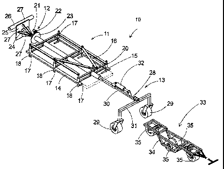
Figure 1 is a perspective view of a new slat carrier according
to the present invention.
Figure 2 is a side view of the present invention with the
support assembly shown in the vertical position.
Figure 3 is a side view of the present invention with the
mounting assembly shown in a lowered position.
Figure 4 is an enlarged perspective view of the securing
assembly of the present invention.
4
CA 02453472 2003-12-17
DESCRIPTION OF THE PREFERRED EMBODIMENT
With reference now to the drawings, and in particular to
Figures 1 through 4 thereof, a new slat carrier embodying the
principles and concepts of the present invention and generally
designated by the reference numeral 10 will be described.
As best illustrated in Figures 1 through 4, the slat carrier 10
generally comprises a support assembly 11 being designed for
selectively receiving the slat to be transported.
A mounting assembly 12 is rotatably coupled to the support
assembly 11. The support assembly 11 is rotated with respect to
the mounting assembly 12 whereby the support assembly 11 is
designed for rotating the slat from a horizontal position to a
vertical position to facilitate transportation of the slat through
doorways. The mounting assembly 12 is designed for being
selectively coupled to a vehicle whereby the mounting assembly 12
permits the vehicle to transport the slat supported by the support
assembly 11.
A wheel assembly 13 is coupled to the mounting assembly 12.
The wheel assembly 13 is designed for engaging a support surface
whereby the wheel assembly 13 facilitates transportation of the
support assembly 11 across the support surface.
The support assembly 11 comprises a frame member 14 and a
pivot member 15. The frame member 14 is coupled to the pivot
member 15 whereby the frame member 14 is designed for supporting
the weight of the slat. The pivot member 15 is positioned around a
portion of the mounting assembly 12 whereby the pivot member 15
selectively rotates around the mounting assembly 12 to allow the
5
CA 02453472 2003-12-17 ''
slat to be selectively pivoted between a horizontal position and a
vertical position.
The support assembly 11 comprises a securing assembly 16.
The securing assembly 16 is operationally coupled to the frame
member 14. The securing assembly 16 is designed for engaging the
slat whereby the securing assembly 16 is for securing the slat to the
frame member 14.
The securing assembly 16 of the support assembly 11
comprises a plurality of armature members 17. Each of the
armature members 17 is pivotally coupled to the frame member 14.
Each of the armature members 17 is designed for being selectively
pivoted over the slat to secure the slat between the armature
members 17 and the frame member 14 to secure the slat member to
the frame member 14 when the slat is positioned adjacent the frame
member 14.
Each of the armature members 17 comprises a pivot portion 18
and an extension portion 19. The pivot portion 18 of each of the
armature members 17 is pivotally coupled to the frame member 14.
The extension portion 19 is coupled to the pivot portion 18 of the
associated one of the armature members 17 opposite the frame
assembly. The extension portion 19 of each of the armature
members 17 is designed for being selectively extended over the slat
to secure the slat to the frame member 14 when the pivot portion 18
of the associated one of the armature members 17 is pivoted with
respect to the frame member 14.
The securing assembly 16 comprises a handle member 20. The
handle member 20 is pivotally coupled to the frame member 14.
The handle member 20 is operationally coupled to the armature
6
CA 02453472 2003-12-17
members 17 whereby pivoting of the handle member 20 in a first
direction pivots each of the armature members 17 with respect to
the frame member 14 to secure the slat to the frame member 14.
The handle member 20 is pivotal in a second direction to pivot the
armature members 17 with respect to the frame member 14 to allow
the slat to be removed from the frame member 14.
A motor member 21 is coupled to the mounting assembly 12.
The motor member 21 is operationally coupled to the support
assembly 11 whereby the motor member 21 rotates the support
assembly 11 with respect to the mounting assembly 12 to rotate the
slat between the horizontal position and the vertical position when
the motor member 21 is actuated by the user.
A first gear member 22 is coupled to the motor member 21
whereby the first gear member 22 is selectively rotated by the
motor member 21. A second gear member 23 is coupled to the pivot
member 15 of the support assembly 11. The first gear member 22 is
operationally coupled to the second member whereby the second
gear member 23 is rotated by the first gear member 22 to rotate the
support assembly 11 with respect to the mounting assembly 12 when
the first gear member 22 is rotated by the motor member 21.
The mounting assembly 12 comprises a main member 24. The
pivot member 15 of the support assembly 11 is rotationally coupled
to the main member 24 of the mounting assembly 12. The main
member 24 is designed for being selectively coupled to the vehicle
whereby the main member 24 is for supporting the weight of the
slat when the slat is being transported by the vehicle.
The mounting assembly 12 comprises a mounting plate 25.
The mounting plate 25 is coupled to the main member 24 whereby
7
CA 02453472 2003-12-17
the mounting plate 25 is positioned opposite the wheel assembly 13.
The mounting plate 25 is designed for being coupled to the vehicle
whereby the mounting plate 25 secures the mairi member 24 to the
vehicle.
The mounting assembly 12 comprises a sleeve portion 26.
The sleeve portion 26 is coupled to the mounting plate 25. The
sleeve portion 26 is designed for being operationally coupled to the
vehicle whereby the sleeve portion 26 permits the mounting
assembly 12 to maintain a substantially parallel orientation with the
support surface when the mounting assembly 12 is raised and
lowered by the vehicle.
The mounting assembly 12 comprises a plurality of bracing
members 27. Each of the bracing members 27 extends between the
main member 24 and the mounting plate 25 of the mounting
assembly 12 whereby the bracing members 27 are for bracing the
main member 24 when the main member 24 is supporting the weight
of the slat.
The wheel assembly 13 comprises an arm member 28 and a
pair of wheels 29. The wheels 29 are rotatably coupled to the arm
member 28 whereby the wheels 29 are designed for rolling across
the support surface. The arm member 28 is pivotally coupled to the
main member 24 of the mounting assembly 12 whereby the arm
member 28 changes angle with respect to the main member 24 of the
mounting assembly 12 to maintain contact between the wheels 29
and the support surface when the vehicle raises and lowers the
mounting assembly 12.
The arm member 28 comprises a tongue portion 30 and a
stabilizing portion 31. The tongue portion 30 is pivotally coupled
8
CA 02453472 2003-12-17
to the main member 24 of the mounting assembly 12. The
stabilizing portion 31 is coupled to the tongue portion 30 whereby
the stabilizing portion 31 is positioned. opposite the mounting
assembly 12. The wheels 29 are rotatably coupled to the stabilizing
portion 31 whereby the wheels 29 are positioned in a spaced
relationship to inhibit tipping of the support assembly 11. The
mounting assembly 12 and the wheel assembly 13 when in use.
A biasing member 32 is coupled to the main member 24 of the
mounting assembly 12 and the arm member 28 of the wheel
assembly 13. The biasing member 32 biasing the arm member 28 of
the wheel assembly 13 away from the mounting assembly 12
whereby the biasing member 32 is for biasing the wheels 29 against
the support surface when the mounting assembly 12 is being raised
and lowered by the vehicle. The biasing member 32 may comprise a
ram to maintain contact between the wheels 29 and the support
surface.
A cart assembly 33 is selectively positionable under the
support assembly 11 when the support assembly 11 is in a
horizontal position. The cart assembly 33 is designed for
supporting the slat above the support surface whereby the cart
assembly 33 supports the slat under the support assembly 11 when
the support assembly 11 is receiving the slat.
.
The cart assembly 33 comprises chassis member 34 and a
plurality of rollers 35. The chassis member 34 is designed for
receiving the slat in a horizontal position. Each of the rollers 35 is
rotatably coupled to the chassis member 34 whereby the rollers 35
are designed for rolling across the support surface to facilitate
9
CA 02453472 2003-12-17
movement of the chassis member 34 and the slat across the support
surface.
In use, the user places a slat onto the chassis member 34 of
the cart member and positions the slat under the frame member 14
of the support assembly 11. The vehicle lowers the mounting
assembly 12 so that the frame member 14 of the support assembly
11 abuts the slat member. The user then pivots the handle member
20 in the first direction to pivot the armature members 17 to engage
the slat and secure the slat between the armature members 17 and
the frame member 14. The vehicle is then used to raise the
mounting assembly 12 and the cart assembly 33 is removed from
below the support assembly 11. The motor member 21 is then
actuated to rotate.s the support assembly 11 and the slat into a
vertical position. The vehicle then tows mounting assembly 12, the
wheel assembly 13 and the support assembly 11 with the slat
through a doorway so that the slat is positioned in the animal pen.
The motor member 21 is actuated again to rotate the support
assembly 11 and the slat back into the horizontal position and the
mounting assembly 12 is lowered by the vehicle. The handle
member 20 is pivoted in the second direction so that the armature
members 17 pivot and disengage the slat so that the slat can be
placed on the floor of the animal pen and then placed in the desired
location. The vehicle then raises the mounting assembly 12 and the
rimotor member 21 is actuated to rotate the support assembly 11 into
the vertical position so that the mounting assembly 12, the support
assembly 11 and the wheel assembly 13 can be transported through
the doorway to repeat the process for the desired number of slats to
be placed in the animal pen.
CA 02453472 2003-12-17
With respect to the above description then, it is to be realized
that the optimum dimensional relationships for the parts of the
invention, to include variations in size, materials, shape, form,
function and manner of operation, assembly and use, are deemed
readily apparent and obvious to one skilled in the art, and all
equivalent relationships to those illustrated in the drawings and
described in the specification are intended to be encompassed by
the present invention.
Therefore, the foregoing is considered as illustrative only of
the principles of the invention. Further, since numerous
modifications and changes will readily occur to those skilled in the
art, it is not desired to limit the invention to the exact construction
and operation shown and described, and accordingly, all suitable
modifications and equivalents may be resorted to, falling within the
scope of the invention.
il