Note: Descriptions are shown in the official language in which they were submitted.
CA 02453780 2003-12-22
3fy~°id 'Telepho~ay Device
BACI~Git~UlI~D
Field of the Invention
[0001] The present invention relates generally to a telephony device and, more
particularly, to a telephony device that uses powers ~°~ro~n two or
more sources.
Background of the Invention
[0002] Conventional telephones includes those that are line (PSTN) powered.
Line
powered telephones usually offer only very basic functionality as there are
very
stringent limits imposed by regulatory authorities on the amount of current
that can be
drawn off the PSTN line both for on-hook and off hook conditions. For example,
during an on-hook condition, the telephone must represent an impedance of
greater
than 5 MS2 (5,000;000 ohms). With on-hook voltages as low as 25 V (or possibly
lower than 25 V depending on the central office, loop length, and other
factors), this
represents a maximum current draw of less than 5 ~,A (5 micro amps). ~,
typical
radio transceiver device, e.g., a cordless telephone, operating in standby
mode would
have a peak current draw many time greater than this, thereby precluding the
possibility of any type of radio communication while the device is on-hook.
This is
clearly an unacceptable functional limitation as any cordless telephony device
must
be able to respond to radio communication initiated by the cordless handset
prior to
the base device going off hook.
[0003] Most cordless telephones today have advanced functions that require the
base
unit to be connected to a PST'N line and an external power source to enable
proper
operation of the advanced functions. The need for the external power source,
e.g.,
AC power outlet, is associated with a number of disadvantages. First, a power
adapter that is cumbersome and esthetically unappealing is required. Second,
the
telephone must be placed at ~ location where the PST'C~ line and the AC power
outlet
are co-located. Third, the telephone ceases to operate during power failure
events.
1
CA 02453780 2003-12-22
[000.) Therefore, users have to choose between a line-powered corded telephone
that
offers very simple functionality with no external power required and a more
fully
featured device that utilizes a~ external power connection. There is not any
telephony
device i.n the market that provides full functionality without requiring an
external
power connection.
SIJIVIlVIAR~' F 'TIDE IhI~EI~'TIl~
[0005) The invention provides a telephony device that provides more
functionality
than a conventional line-powered telephone without :requiring an AC dower
source.
The preferred embodiments of the invention includes a mechanism that allows a
telephony device to be powered by the PSTII~ line directly and augmented
through the
use of batteries.
[0006] A preferred embodiment of the invention provides a device that includes
a
circuit configured to draw current from a f S TILT source during a first
condition and
from a battery source during a second condition. 1'ref~rably, the circuit is
defaulted to
draw current from the battery source. The first condition can be associated
with an
off-hook condition. The second condition can be associated with an on-hook
condition. Preferably, the device further includes a base unit and a handset,
and the
battery source is located at the base unit. The base unit and the handset
maintains a
periodic radio communication during the second condition.
[0007] Another preferred embodiment of the invention provides a telephone that
includes a base unit, a battery, and a microcontroller. The base unit is
configured to
communicate with a PSTiV. The battery is housed within the base unit. The
microcontroller is housed within the base unit, and it is configured to
generate a first
signal during an off hook condition and a second signal during ari on-hook
condition.
The first signal results in current being drawn exclusively from the PSTN and
the
second signal results in current being drawn exclusively from the battery.
Preferably,
the first signal is a high control signal and the second signal is a low contl-
ol sigrgal.
Preferably, the battery includes a primary battery cell. For example, the
battery
includes an alkaline battery cell. Alternatively or in addition to the primary
battery
CA 02453780 2003-12-22
cell, the battery can include a rechargeable battery cell. Preferably, the
telephone
further includes a battery charger that is housed within the based unit. The
battery
charger is configured to draw current from the PSTl~f to recharge the
rechargeable
battery cell.
[0008) Another preferred embodiment of the invention provides a cordless
telephone
that includes a base unit, a battery source housed within the base unit, a
handset
configured to communicate with the base unit using radio communication, and a
microeontroller housed within the base unit. The microcontroller is configured
to
generate a control signal that is either high or low depending on a mode of
operation
of the device. The cordless telephone further includes means for drawing
current
from one of the PSTN source and the battery source depending on v~hether the
control
signal is high or low. Preferably, the current is drawn from the PSTN source
when
the control signal is high and the current is drawn from the battery source
when the
control signal is low. Preferably, a low control signal is associated with a
mode of
operation that does not involve a radio communication betty een the base unit
and the
handset, and a high control signal is associated with a mode of operation that
involves
a radio communication between the base unit and the handset:
[00~9] Another preferred embodiment of the invention provides a method that
includes the follov~.~ing steps. A device is defaulted to draw current frown a
battery
source. A mode of operation ofthe device is monitored. If the mode of
operation
involves an on-hook condition, then current is continued to be drawn from the
battery
source. If the mode of operation involves an off hoof condition, then current
is
drawn from a PSTN source. Preferably, the method farther includes generating a
control signal that is either high or low depending on the mode of operation.
F'or
example, the current is drawn from the PSTN source when the control signal is
high
and from the battery source when the con'~rol signal is low. Preferably, the
method
further include recharging the battery source with current drawn from the PSTN
source.
3
CA 02453780 2003-12-22
BRIEF DESCRIPTI01~1 OF THE DRAWINGS
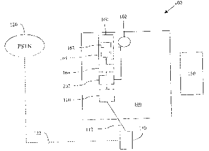
[0010] Figure 1 is a schematic diagram showing an exemplary layout of a
telephony
device of the invention.
[0011 ] Figure 2 is an exemplary power source switch control circuit that can
be used
to implement a telephony device of the invention.
[0012] Figure 3 is a flowchart showing exemplary steps involved in a preferred
embodiment of the invention.
DETAILED DESCRIPTIOhT OF THE I1~TVEhTTI~C~N
[0013] As disclosed herein, telephony devices of the invention include any
apparatus
that can be used to initiate or receive a telephone call, or is otherwise
configured to
utilize the PSTN for voice and data comrr~unication. hor example, the
telephony
devices include telephone sets (conventional corded and cordless telephones)
as well
as computers that are equipped to communicate via the PSTN or ~ther telephone
networks. An exemplary telephony device of the invention is described below as
a
cordless telephone.
[0014] Figure 1 is a schematic diagram showing the layout of an exemplary
telephony device of the invention. Although device 100 is described herein as
a
cordless telephone, it is noted that device 100 can be another telephony
device on
which the present invention can be implemented.
[OOIS] Phone jack 110 of device 100 is connected to ~c~aall outlet 130 by
telephone
cord 112. Through wall outlet 130, device 100 communicate~ns with PSTN 120 via
telephone line 122. As known in the art, PSTN 120 supplies device 100 with
telephone signals as well as an electrical current. The electrical current can
be used to
power basic components of device 100 including, for example, ringer 102 of
device
100. The current is insufficient, however, to support more advanced fuilctions
including, for example, radio communication between base unit 140 and handset
150.
Handset 150 has its own battery source as known in tJ~e art.
4
CA 02453780 2003-12-22
[0016] Battery 160 is conf gored to supply a current when no power can be
drawn
from PSTN 120. The cu~°ent supplied by battery 160 is sufficient to
support the more
advanced functions of device 100. For example, battery I 60 is used to power
radio
communication between base u:oit 140 and handset 1 ~0 during an on-hook
operation
mode of device 100. Battery 160 can include primary or secondary batteries, or
both.
[0017] In the preferred embodiment of the invention, battery 160 includes
primary
battery cells 162. Preferably, battery cells 162 are high capacity alkaline
cells. For
example, typical "C" and "I~" batteries may be used. In alternative
embodiments,
other battery cells may be used. For example, rechargeable cells 164 may be
included
in battery 160 in an alternative embodiment. In this alternative embodiment,
excess
current available from the PSTN line (not required by the base circuitry)
could be
redirected to slowly charge the rechargeable cells 164 wrhile the system is
off hook:
Recharging can be performed by, for example, battery charger 166 that is in
communication with rechargeable cells 164. i~ependang on regulations, the
total
current drawn off the PSTN line does not exceed the maximum allowed by the
regulating agency (e.g., the FCC in the United States). Preferably, the
rechargeable
cells 164 are supplied with device 100 in a fully charged condition.
[0018] l~ preferred embodiment of device 100 has the following exemplary
characteristics:
~ It is powered by PSTN 120 but is augmented by power from battery 160;
~ It has the ability to receive power from battery 160 during an ~~n-hook
condition and from PSTN 120 automatically when it enters an off hook
condition;
~ It has the ability to supplement PSTN 120 power with battery 160 power
in the event that device 100 current requirements exceed What can be
drawn from PSTN 120 while off hook;
~ It provides enhanced telephony functions ~c.g., cordless operation) without
requiring an AC power connection;
CA 02453780 2003-12-22
~ It does not experience interruption in operation in the event of an AC
power failure: and
~ It utilizes battery 160 only during on-hook conditions where the current
consumption is least, thereby maximizing the life of the batteries (e.g., 6
months or longer)m
[0019] device 100 includes circuit 200. An exemplary circuit 200 is depicted
in
Figure 2. Battery 160 and phone jack 110 are in conunur~ication with circuit
200.
Circuit 200 is configured to switch between 1'STN power (drawn from PSTN 120
via
phone j ack 110) and battery power (drawn from battery 1 S0). Circuit 200 also
allows
battery 160 to supplement the current that can be dra~x~n off PSTN 120 in
modes of
operation where the amount of current required by base unit 140 is greater
than the
maximum that can be drawn off PSTN 120 alone.
[0020] Circuit 200 operates basically as a switch dra~~ing power either from
PSTN
120 or from battery 160. Although it is possible to receive current from
battery 150
to supplement current from PSTN 120, circuit 200 shown in Figure 2 does not
support that function. Circuit 200 is configured to function in a way that
when device
100 is off hook and requiring the most current (i.e., radio transmitting and
receiving
continuously), circuit 200 disconnects battery 160 and draws power from PSTN
120
only. Battery 160 is only used to supply power duriry an on-hook condit:i~n
when the
amount of current that the FCC allows device 100 to draw off the PSTN
a~ormection is
too low to power the circuit at all.
[0021] Circuit 200 is in communication with microcontroller 210.
I~icrocontroller
210 produces a control signal. The control signal is preferably digital in
nature. The
control signal can be high. or low, ~rrhich determines whether the power is
taken from
the PSTN source or from the battery source. A high control signal can be
associated
with an off hook condition. A low control signal can be associated with an on-
hook
condition. In one specific embodiment as shown in circuit 200, the high
control
signal can be associated with a situation in which cordless handset 150 is
being used
during a communication session via PSTN 120, and the low control signal can be
6
CA 02453780 2003-12-22
associated ~.vith a radio communication between handset 150 and base unit I40
during
an on-hook condition.
[0022] In a preferred embodiment, if the control signal is high, current flows
through
IZ3 and ~2 is turned on. base bias is allowed to flow through R2 and ~ I turns
on.
With Q1 on, the voltage of the PSTN source (VPS~~ is applied to the input of
voltage
regulator 220 and the 3.6 V output from voltage rega:dator 220 flows through
I) 1 and
supplies about 3 VDC to Vout to power the base circuitry. In this state, ~3 is
off and
the voltage of the batter source (V$at~~ is isolated from Vo~,t.
[0023] If the control signal is low, (~2 is off, C,~1 is also off, and ~PS~ is
not applied
to the input of voltage regulator 220 and the combinf,d impedance presented to
the
PSTN line must be more than about 5 M~. IJikewise, with the control signal
low, ~3
is turned on by virtue of current now being allowed to flow through R4 and R6.
With
(~3 on, V~att is connected to Vout and will be isolated from the output of
voltage
regulator 220 by I~ 1.
[0024] Cl holds the output voltage at about 3 VL» for a short period of time
to allow
circuit 200 to function nomnally during the transition between PSTN power and
battery power as the operation of V~onITO~ depends on ~~~out having 3 VI3C
present. The
maximum current drawn off IPS-;-~ is Less than 30 mA as many central office
switches
are now limiting the loop current to a maximum of 30 m~. Vo"t is what powers
the
rest of base unit 140. Preferably, ~ 1 is positioned such that it can smooth
out any
supply voltage transients that could result from switching between power
sources.
[0025] Figure 3 is a flowchart showing exemplary steps involved in a preferred
embodiment of the invention.
[0026] In step 302, base unit of device l Ot) is defaulted to draw current
from battery
160. This default ensures that a radio communication between handset 150 and
base
unit I40 can be maintained during an on-hook condition.
[0027] In step 304, device 100 monitors the mode of operation. For example,
device
100 is configured to deteramine whether it is in an on-hook condition or an
off hook
condition.
7
CA 02453780 2003-12-22
[0028] In step 306, if an outside stimulus is detected, the process goes to
step 310.
~therwise, the process goes to step 308. The outside stimulus can occur when;
for
example, handset 150 co~~nmunicates its intent to dial or there is an incoming
ringing
on the PSTN Iine. As known in the art, a microprocessor of device 100 controls
all
functions of device 100. The microprocessor first senses the change in
condition,
initiates the off hook condition, and then initiates the change in power
source.
[009) In step 308, so Iong as device 100 remains in an on-hook condition, base
unit
140 continues to draw current from battery 160. This can be implemented using
microcontroller 210 that generates a low signal so that current is drawing
from Battery
160 as shown in Figure 2 and described above. The process then returns to step
304.
[0030] In step 310, when device 100 enters an off hook condition, e.g., a
communication session has been established with PSTN 120, current is drawn
from
PST3~T 120 in stead of from battery 160. .~s shown in Figure 2 and described
above;
this can be implemented by microcontroller 210, which generates a high control
signal so that circuit 200 .draws current from PSTN 120.
[0031] The foregoing disclosure ofthe preferred embodinnents of the present
invention has been presented for purposes of illustration and description. It
is not
intended to be exhaustive or to Iimit the invention to the precise forms
disclosed.
Many variations and modifications of the embodiments described herein will be
apparent to one of ordinary skill in the art in light of ~~e above disclosure.
The scope
of the invention is to be defined only by the claims appended heret~, and by
their
equivalents.
[0032] Further, in describing representative embodiments of the present
invention,
the specification may have presented the method and/or process ofthe present
invention as a particular sequence of steps. However, to the extent that the
method or
process does not rely on the particular order of steps set forth herein, the
method or
process should not be limited to the particular sequence of steps described.
As one of
ordinary skill in the art would appreciate, other sequences of steps may be
possible.
Therefore, the particular order of the steps set forth in the specification
should not be
construed as limitations on the claims. In addition, the claims directed to
the method
8
CA 02453780 2003-12-22
and/or process of the present invention should not be limited to the
performance of
their steps in the order wa°itter~, and one skilled in the ~z°~
can readily appreciate that
the sequences may be v aried and still remaiwvithin l:l~e spirit and scope of
the present
inventions
9