Note: Descriptions are shown in the official language in which they were submitted.
CA 02454575 2004-O1-19
WO 03/011689 PCT/US02/24729
HELICOPTER MAIN ROTOR BLADE BALANCE WEIGHT RETENTION ASSEMBLY
Technical Field
The present invention relates generally to helicopter rotor blades. In
particular,
the present invention relates to systems and assemblies for retaining balance
weights for
adjusting the spanwise and chordwise balance of the rotor blades.
Description of the Prior Art
It is important that helicopter rotor blades are balanced properly in both
spanwise
and chordwise directions. Improperly balanced blades not only cause excessive
vibrations due to imbalance, but also cause increased loads in critical
dynamic
components. The end result is degraded flying qualities and reduced component
lives
due to premature fatigue failure.
The blades require both spanwise and chordwise balance. For static balance,
the
rotor blade is balanced relative to a master blade prior to installation of
the rotor blade
onto the helicopter. For dynamic balance, the blade is balanced either on a
whirl stand
or on the helicopter against a master blade or other blades it would fly with.
These
adjustments are made using balance weights installed inside the blade
structure near the
tip. The blades typically have leading edge and trailing edge pockets near the
tip for
housing spanwise and chordwise balance weights. Numerous mechanisms are
currently
employed in retaining the balance weights in these pockets. These balance
weight
retention mechanisms usually consist of a housing, one or more balance
weights, one or
more fastening bolts for securing the balance weights to the housing, and one
or more
covers that are shaped to match the contour of the rotor blade.
There are several problems associated with conventional balance weight
retention
systems. In some designs, the pockets in the tip of the rotor blade run
completely
through the thickness of the rotor blade causing the blade to significantly
lose its stiffness
and strength. This requires additional structure to make up for the loss of
stiffness. In
other designs, the threaded shanks of the fastening bolts are subjected to
shear loads
from balance weights due to the centrifugal force generated by the rotating
rotor blades.
CA 02454575 2004-O1-19
WO 03/011689 PCT/US02/24729
-2-
Higher stresses in the threaded shanks due to high stress concentrations at
the root of
the threads can lead to failure of the fastening bolts, and, ultimately,
failure of the entire
balance weight retention mechanism. In yet other designs, fastening studs are
provided
so that the fastening bolts do not come into contact with the balance weights.
However,
in these other designs, the balance weights are in contact with the exterior
walls of the
housing, thereby, transferring the shear load through this interface. This
makes the
installation and removal of the balance weights more difficult. In most of
these
conventional balance weight retention systems, precision machining of the
pockets in the
blade tips is required for proper installation of the housing. This is time
consuming,
costly, and labor intensive.
Another limitation with conventional balance weight retention mechanisms is
that,
although they may be useful for new blade construction, they do not provide
adequate
provisions for rebalancing rotor blades that have undergone patching,
reconstruction,
repairs, or modifications.
Although great strides have been made in the area of helicopter rotor blade
tip
balancing, significant shortcomings remain.
Summary of the Invention
There is a need for a helicopter main rotor balance weight retention assembly
in
which the threaded portions of the fastening bolts are not subjected to any
shear loads
from the balance weights due to the centrifugal force generated by the
rotating rotor
blades, and for which the cavities in the blade tip do not have to be
precision machined.
There is also a need for a helicopter main rotor balance weight retention
assembly
that can be used to balance not only rotor blades of new construction, but
rotor blades
that have undergone patching, reconstruction, repairs, or modifications.
Therefore, it is an object of the present invention to provide a helicopter
main rotor
balance weight retention assembly in which the threaded portions of the
fastening bolts
are not subjected to any shear loads from the balance weights due to the
centrifugal
force generated by the rotating rotor blades, and for which the pockets in the
blade tip do
not have to be precision machined.
CA 02454575 2004-O1-19
WO 03/011689 PCT/US02/24729
-3-
It is another object of the present invention to provide a helicopter main
rotor
balance weight retention assembly that can be used to balance not only rotor
blades of
new construction, but rotor blades that have undergone patching,
reconstruction, repairs,
or modifications.
The above objects are achieved by providing a helicopter main rotor blade
balance weight retention system and assembly having a base plate, at least one
support
post integral with the base plate and extending out perpendicularly from the
base plate, a
plurality of balance weights, a retaining nut plate, and one or more fastening
bolts for
securing the balance weights to the base plate and the base plate to the rotor
blade.
The balance weights include apertures through which the support posts and the
fastening bolts pass. The apertures through which the support posts pass are
dimensioned such that the a snug fit is formed between the support posts and
the
balance weight; but the apertures through which the fastening bolts pass are
dimensioned such that the threaded portions of the fastening bolts are not
subjected to
any shear loads from the balance weights due to the centrifugal force
generated by the
rotating rotor blades. The weight retention assembly is installed into pockets
in the blade
tip. The pockets do not have to undergo precision machining to receive and
enclose the
balance weight retention assemblies. One of the pockets includes an additional
balance
weight retention assembly in which the balance weights are smaller than the
balance
weights in the main balance weight retention assembly. This provides an
additional
means of fine tuning the spanwise and chordwise balance of both new rotor
blades, and
used rotor blades that have been patched, reconstructed, repaired, or
modified.
The present invention provides the following advantages: (1 ) the threaded
portions of the fastener bolts are not subjected to any shear loads from the
balance
weights due to the centrifugal force generated by the rotating rotor blade;
(2) the
fastening bolts serve a dual purpose of securing the balance weights to the
base plate
and the base plate to the rotor blade; (3) only one length of faster bolt is
required for
various combinations of balance weights; (4) the fastening bolts do not pass
through the
cover; (5) the cover can be lighter and provide a better fit with the contour
of the rotor
blade; (6) no spacer shims are required; (7) the pocket in the tip of the
rotor blade does
not have to pass entirely through the rotor blade; (8) the pocket in the tip
of the rotor
CA 02454575 2004-O1-19
WO 03/011689 PCT/US02/24729
-4-
blade does not require precision machining; and (9) the additional, smaller
balance
weight retention assembly is easily accessible and provides a means to perform
and fine
tune spanwise and chordwise balance of the rotor blade after patching,
reconstruction,
repairs, or modifications.
The above objects and advantages, as well as others, will be evident from the
following detailed description and drawings of the present invention.
Brief Description of the Drawings
Figure 1 is a perspective view of a helicopter having a main rotor blade
balance
weight retention system according to the present invention.
Figure 2 is a perspective view of a rotor blade of the helicopter of Figure 1.
Figure 3 is an enlarged view of the blade tip of the rotor blade of Figure 2.
Figure 4 is an isometric view of a base plate for a balance weight retention
assembly according to the present invention.
Figure 5 is an isometric view of a balance weight for a balance weight
retention
assembly according to the present invention.
Figure 6 is an isometric view of a retention plate for a first balance weight
retention assembly according to the present invention.
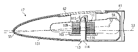
Figure 7 is a cross-sectional view taken at VII-VII in Figure 3.
Figure 8 is a cross-sectional view taken at VIII-VIII in Figure 3.
Figure 9 is an isometric view of a base plate for an additional, smaller
balance
weight retention assembly according to the present invention.
Figure 10 is an isometric view of a balance weight for an additional, smaller
balance weight retention assembly according to the present invention.
Figure 11 is an isometric view of a retention plate for an additional, smaller
balance weight retention assembly according to the present invention.
CA 02454575 2004-O1-19
WO 03/011689 PCT/US02/24729
-5-
Description of the Preferred Embodiment
Referring to Figure 1 in the drawings, a helicopter 11 having a main rotor
blade
balance weight retention system 12 according to the present invention is
illustrated.
Helicopter 11 includes a fuselage 13 and a main rotor 15. Main rotor 15
includes a
plurality of main rotor blades 17 that are coupled to one or more rotor yokes
19 and a
drive mast 31. Torque imparted to fuselage 13 by main rotor 15 is counteracted
by a tail
rotor 21 carried by a tail portion 23 of fuselage 13. Tail rotor 21 includes a
plurality of tail
rotor blades 25 that are coupled to a tail rotor hub 27. Main rotor 15 and
tail rotor 21 are
powered by a drive means 29 under the control of a pilot in a cockpit 33. Each
rotor
blade 17 has an inboard root end 35 and an opposing outboard blade tip 37. The
root
end 35 of each rotor blade 17 is coupled to one of rotor yokes 19. One balance
weight
retention system 12 for selectively providing and adjusting the spanwise and
chordwise
balance of rotor blade 17 is operably associated with each blade tip 37.
Referring now to Figure 2 in the drawings, one rotor blade 17 of helicopter 11
is
shown in a perspective view. Rotor blade 17 includes structures and
components, such
as spars, ribs, cores, and skins made from composite, honeycomb, and metallic
materials. Rotor blade 17 has a pitch change axis 51 that extends in a
direction from
root end 35 to blade tip 37; a center of twist axis 52 that extends in a
direction from root
end 35 to blade tip 37; and a chord axis 53, which is generally perpendicular
to pitch
change axis 51, that extends in a direction from a leading edge 55 of rotor
blade 17 to a
trailing edge 57 of rotor blade 17. In the preferred embodiment a forward
pocket 59
spans pitch change axis 51 and chord axis 53; and an aft pocket 60, which is
aft of and
generally parallel to forward pocket 59, spans chord axis 53.
Rotor blade 17 includes a self-powered blade tip formation light. This light
is
preferably constructed of two clear plastic pieces with a self-generating
light material,
such as tritium-3, disposed therebetween. In order to provide increased
capability, a
variable intensity blade tip formation light 58 is incorporated on an upper
airfoil surface
61 of rotor blade 17. Light 58 is preferably a 28-Volt DC light and can be
selectively
operated by the pilot in flight. Rotor blade 17 also includes an adjustable
trim tab 56 to
aid in blade tracking.
CA 02454575 2004-O1-19
WO 03/011689 PCT/US02/24729
-6_
A cover 62 protectively encloses forward pocket 59, and a cover 64
protectively
encloses aft pocket 60. Covers 62 and 64 are preferably configured to match
the
contour of an upper airfoil surface 61. Covers 62 and 64 are preferably made
of a
metallic material, such as aluminum or steel, and are removably secured to
rotor blade
17 by conventional fasteners 66 that are received by conventional metallic
inserts (not
shown) installed in the composite spars and/or ribs of rotor blade 17. To
maintain
structural integrity, it is preferred that pockets 59 and 60 extend only
partially through
rotor blade 17 from upper airfoil surface 61, such that pockets 59 and 60 are
only open to
upper airfoil surface 61 of rotor blade 17. It should be understood that
pockets 59 and 60
may be open to a lower airfoil surface 131 (see Figures 7 and 8). ,
Referring now to Figure 3 in the drawings, a first balance weight retention
assembly 75 is disposed within forward pocket 59, and a second balance weight
retention assembly 77 is disposed within aft pocket 60. An additional,
smaller, balance
weight retention assembly 79 is also disposed within forward pocket 59 to
ensure track
and balance capability after patching, reconstruction, repairs, or
modifications to rotor
blade 17. Balance weight retention assembly 79 is preferably adjacent to,
aligned with,
and inboard of, balance weight retention assembly 75 along pitch change axis
51.
Balance weight retention assemblies 75, 77, and 79 allow for both spanwise and
chordwise dynamic balancing of rotor blade 17. Because of its smaller size,
additional
balance weight retention assembly 79 is particularly well suited for fine
tuning of the
balance of rotor blade 17 after patching, reconstruction, repairs, or
modifications to rotor
blade 17. Although forward pocket 59 has a generally rectangular shape, and
aft pocket
60 has a generally oval shape, it should be understood that pockets 59 and 60
may be of
varying geometrical shapes.
Referring now to Figures 4-8 in the drawings, balance weight retention
assemblies
75 and 77 are preferably similar in form and function. Balance, weight
retention
assemblies 75 and 77 each include a base plate 105, at least one support post
107
integral with base plate 105, at least one balance weight 109, a retaining
plate 111, at
least one fastening bolt 113, and a nut plate 115 carried by retaining plate
111 for each
fastening bolt 113. Fastener bolts 113 preferably include a flush-mount head
114, an
CA 02454575 2004-O1-19
WO 03/011689 PCT/US02/24729
_7_
unthreaded shank portion 116, and a threaded portion. Nut plates 115 include
fastener
receivers for matingly receiving the threaded portions of fastener bolts 113.
Base plate 105 is preferably made of a metallic material, such as aluminum or
steel. Support posts 107 are preferably integral with base plate 105 and
extend out
perpendicularly from base plate 105. As best shown in Figure 8, support posts
107 may
include a hollow cavity 108 to conserve weight. In the preferred embodiment,
base plate
105 is bonded to the interior surface of pocket 59 with a conventional
adhesive. Balance
weights 109 are preferably made of a metallic material, such as steel or
tungsten, and
are of uniform thickness, preferably 0.050 of an inch. However, some balance
weights
109 made be made of lighter material, such as aluminum, and may be of thinner
thickness, such as 0.025 of an inch. This variation in material and thickness
allows for
fine tuning of balance weight retention assemblies 75 and 77. Base plate 105
includes
slightly upraised fastener guides 121 for guiding fastener bolts 113 and
lifting balance
weights 109 slightly away from base plate 105. Fastener guides 121 include
apertures
123 through which fastener bolts 113 pass. To aid the bonding of base plate
105 to the
interior surface of pocket 59, unthreaded shank portions 116 of fastener bolts
113 may
be subjected to some shear load from base plate 105 through fastener guides
121 due to
the centrifugal force generated by rotating rotor blade 17.
Balance weights 109 include an aperture 117 for each support post 107 to pass
through, and an aperture 119 for each fastening bolt 113 to pass through. It
is preferred
that a snug fit exist between each support post 107 and each aperture 117, but
that a
clearance exist between each fastening bolt 113 and each aperture 119. This
configuration ensures that all of the shear loads from balance weights 109 due
to the
centrifugal force generated by rotating rotor blade 17 are transferred to
support posts
107, and not to the threaded portions of fastener bolts 113. In addition, a
clearance
exists between the peripheral edges of balance weights 109 and the interior
walls of
pockets 59 and 60. This configuration ensures that none of the shear loads
from
balance weights 109 due to the centrifugal force generated by rotating rotor
blade 17 are
transferred directly to the interior walls of pockets 59 and 60. This
configuration also
ensures that pockets 59 and 60 do not have to undergo precision machining to
receive
and enclose balance weight retention assemblies 75 and 77.
CA 02454575 2004-O1-19
WO 03/011689 PCT/US02/24729
_g_
In operation, retaining plate 111 is disposed atop the uppermost balance
weight
109. Nut plates 115 are coupled to retaining plate 111 by conventional means,
such as
rivets or by welding. Nut plates 115 include internal threads to receive the
threaded
portions of fastening bolts 113. In the preferred embodiment, nut plates 115
may include
bosses that extend perpendicularly downward through apertures 119 in balance
weights
109 to receive fastener bolts 113.
Balance weight retention assemblies 75 and 77 are assembled by installing base
plates 105 into pockets 59 and 60. In the preferred embodiment, base plates
105 are
coupled to the interior of pockets 59 and 60, preferably by bonding with a
conventional
adhesive. Once base plates 105 are installed, balance weights 109 are stacked
on top
of base plates 105, such that support posts 107 pass through apertures 117 in
balance
weights 109. As set forth above, it is preferred that a snug fit between
support posts 107
and apertures 117 be achieved. After an appropriate number of balance weights
109
have been installed onto base plates 105, retaining plates 111 are installed
over posts
107. Then, fastening bolts 113 are passed through aligned apertures in lower
airfoil
surface 131 (see Figure 7), through apertures 123 in fastener guides 121,
through
apertures 119 in balance weights 109, and are fastened to nut plates 115 to
provide
vertical compression of balance weights 109 and to ensure that balance weights
109 do
not move relative to base plate 105 while in operation. Balance weights 109
are added
or removed during spanwise and chordwise dynamic balancing by reversing this
process.
Referring now to Figures 9-11 in the drawings, balance weight retention
assembly
79 is preferably smaller and of slightly different design than balance weight
assemblies
75 and 77. Balance weight retention assembly 79 is a fine adjustment balance
weight
retention assembly and includes a base plate 205, at least one balance weight
209, a
retaining plate 211, at least one fastening bolt (not shown, but similar to
fastening bolt
113), and a nut plate 215 carried by retaining plate 211 for each fastening
bolt. Nut plate
215 is a fastener receiver for matingly receiving the threaded portion of the
fastener
bolts.
CA 02454575 2004-O1-19
WO 03/011689 PCT/US02/24729
_g_
Base plate 205 is preferably made of a metallic material, such as aluminum or
steel. In the preferred embodiment, base plate 205 is coupled to the interior
surface of
forward pocket 59, preferably by bonding with a conventional adhesive. Balance
weights
209 are preferably made of a metallic material, such as steel or tungsten, and
are of
uniform thickness, preferably 0.050 of an inch. However, some balance weights
209
made be made of lighter material, such as aluminum, and may be of thinner
thickness,
such as 0.025 of an inch. This variation in material and thickness allows for
fine tuning of
balance weight retention assembly 79. Base plate 205 includes slightly
upraised
fastener guides 221 for guiding the fastener bolts and lifting balance weights
209 slightly
away from base plate 205. Fastener guides 221 include apertures 223 through
which
the fastener bolts pass.
Balance weights 209 include an aperture 219 for each fastening bolt to pass
through. A clearance exists between the peripheral edges of balance weights
109 and
the interior walls of pocket 59. This configuration ensures that none of the
shear loads
from the centrifugal forces generated by rotating rotor blade 17 are
transferred directly to
the interior walls of pocket 59. This configuration also ensures that pocket
59 does not
have to undergo precision machining to receive and enclose balance weight
retention
assembly 79.
In operation, retaining plate 211 is disposed atop the uppermost balance
weight
209 to provide vertical compression of balance weights 209 and to ensure that
balance
weights 209 do not move relative to base plate 205 while in operation. Nut
plates 215
are coupled to retaining plate 211 by conventional means, such as rivets or by
welding.
Nut plates 215 include internal threads to receive the threaded portions of
the fastening
bolts. In the preferred embodiment, nut plates 215 may include bosses that
extend
perpendicularly downward through apertures 219 in balance weights 209 to
receive the
fastener bolts.
Balance weight retention assembly 79 is assembled by installing base plate 205
into pocket 59. In the preferred embodiment, base plate 205 is bonded to the
interior of
pocket 59 by a conventional adhesive. Once base plate 205 is installed,
balance weights
209 are stacked on top of base plate 205. After an appropriate number of
balance
CA 02454575 2004-O1-19
WO 03/011689 PCT/US02/24729
-10-
weights 209 have been installed onto base plate 205, retaining plate 211 is
installed.
Then, the fastening bolts are passed through aligned apertures in lower
airfoil surface
131 (see Figure 10), through apertures 223 in fastener guides 221, through
apertures
219 in balance weights 209, and are fastened to nut plates 215. Balance
weights 209
are added or removed during static spanwise balancing and dynamic chordwise
balancing by reversing this process. Because of its smaller size, balance
weight
retention assembly 79 is well suited for fine tuning during spanwise and
chordwise
dynamic balancing of rotor blade 17. In particular, balance weight retention
assembly 79
is useful for fine tuning during balancing after patching, reconstruction,
repairs, or
modifications to rotor blade 17.
The present invention provides the following advantages: (1 ) the threaded
portions of fastener bolts 113 are not subjected to any shear loads from
balance weights
109 due to the centrifugal force generated by the rotating rotor blade 17; (2)
fastener
bolts 113 serve a dual purpose of securing balance weights 109 to base plate
105 and
base plate 105 to rotor blade 17; (3) only one length of fastener bolt 113 is
required for
various combinations of balance weights 109; (4) fastener bolts 113 do not
pass through
covers 60 and 62; (5) covers 60 and 62 can be lighter and provide a better fit
with the
contour of upper airfoil surface 61 rotor blade 17; (6) no spacer shims are
required; (7)
pockets 59 and 60 in rotor blade 17 do not have to pass entirely through rotor
blade 17;
(8) pockets 59 and 60 in rotor blade 17 do not require precision machining;
and (9) the
additional, smaller balance weight retention assembly 79 is easily accessible
and
provides a means to perform and fine tune balancing after patching,
reconstruction,
repairs, or modifications to rotor blade 17.
Although the present invention is shown in a limited~number of forms, it is
not
limited to just these forms, but is amenable to various changes and
modifications without
departing from the spirit thereof.