Note: Descriptions are shown in the official language in which they were submitted.
CA 02454590 2003-12-31
STOWABLE REAR SEAT FOR VEHICLE PASSENGER COMPARTNENTS
FIELD OF THE INVENTION
[0001] The present invention relates to the field of stowable
vehicle seats, and more particularly to a stowable rear seat for
passenger compartments in pick-up trucks and the like.
BACKGROUND OF THE INVENTION
[0002] Modern pick-up trucks and similar vehicles commonly have
a second or subsequent row of one or more seats positioned
rearwardly of the driver's seat. Such second or subsequent rows
of seats are commonly movable so as to provide an increased cargo
area in the vehicle's passenger compartment or "cabin". Such
second and subsequent rows of seats are hereinafter referred to
alternately as "second row seats" and/or as "second row seat
assemblies".
[0003] Second and subsequent row seats for pick-up trucks and
similar vehicles are typically of the general type having a seat
portion and a backrest portion. In the prior art, such second and
subsequent row seats have been provided with an in-use or deployed
design configuration, whereat the seat portion thereof is
substantially horizontal and either touches or is in very close
relationship with the rear wall of the vehicle's cabin, and have
- 1 -
CA 02454590 2003-12-31
been rearward pivotable therefrom towards a raised stowed
configuration, whereat the seat portion is substantially vertical
and substantially adjacent to the cabin rear wall. One
shortcoming with such second row seat designs according to the
prior art, however, is that thus far, in the deployed design
configuration, they have been insufficiently spaced from the rear
wall of the cabin to allow for sufficient angular adjustment of
their respective backrest portions. As such, second row seat
passengers in pick-up trucks and the like have heretofore been
faced with the prospect of riding in significant discomfort in a
seat with a backrest oriented substantially upright.
[0004] Manufacturers of mini-vans and sport utility vehicles
have previously provided second and subsequent rows of seats that
are spaced from the rear wall of the passenger compartment, whilst
also being pivotally movable between a deployed design
configuration and a raised stowed configuration. United States
Patent No. 4,700,989 (Ercilla) discloses a vehicle seat assembly
that is forwardly pivotable from a deployed design configuration
towards a raised stowed configuration. In the deployed design
configuration, the legs of the Ercilla vehicle seat assembly are
locked to fixed attachment rods supported by the vehicle floor.
The front legs of the seat disclosed by Ercilla include a blocking
mechanism that prevents unlocking of the front locking means when
the vehicle seat assembly is in its deployed design configuration.
In order to pivot the vehicle seat assembly from its deployed
design configuration to its raised stowed configuration, a locking
- 2 -
CA 02454590 2003-12-31
means at the rear legs is released, and then the vehicle seat
assembly is pivoted forwardly to the raised stowed configuration.
Ordinarily, the front locking means remains engaged, but it may be
separately released when the seat is in the raised stowed
configuration, if the Ercilla vehicle seat assembly is to be
entirely removed from the vehicle.
[0005] A common problem associated with all seats of the
general type having a raised stowed configuration that is located
forwardly of the deployed design configuration, however, is that
any increased cargo space provided in the passenger compartment of
the vehicle when such a seat assembly is in its raised stowed
configuration is not easily accessible other than by way of a
rearward-facing door or hatchback. That is, users attempting to
load or unload cargo from such vehicles through side-facing doors
will usually encounter significant difficulties, especially
insofar as any second row seats positioned in the raised stowed
configuration may present a serious obstacle to such effort by
partial occlusion of said side-facing doors. It will, of course,
be appreciated that most pick-up trucks are not provided with
rearward-facing doors or hatchbacks. As such, and because any
cargo to be carried in the cabs of pick-up trucks must therefore
be loaded or unloaded through the vehicle's side-facing doors,
forwardly pivoting stowable second row seats have not been
particularly useful in this context.
- 3 -
CA 02454590 2003-12-31
[0006] Over and above any of the aforesaid difficulties that
may be encountered in adapting seat assemblies disclosed by
Ercilla for a particular use as second row seats in the cabs of
pick-up trucks and the like, it is also to be noted that the
Ercilla patent fails to disclose any means for supporting the
vehicle seat assembly in its raised stowed configuration.
However, while the Ercilla patent does not itself disclose a means
for preventing unexpected movement of the seat assembly towards
the deployed design configuration during acceleration of the
vehicle so as to thereby avoid damage to any cargo stored
therewithin, the production version of this device actually uses
a strap connected between the seat portion and the mini-van roof
for this purpose. The strap provided in the production version of
this device, however, is quite awkward to employ and aesthetically
unpleasing, whilst also potentially posing a serious safety
problem in crash-like situations, where the loading on such a
strap can be unusually high. Moreover, it should also be
appreciated that strap arrangements permit an inherent degree of
pivotal movement of the raised stowed seat in at least one
direction, which movement results in unacceptable movement,
squeaks, rattles and other noise during travel of the vehicle over
rough terrain or other surfaces. Thus, among other things, it
will be seen to be desirable to rigidly secure a second row
vehicle seat assembly in the raised stowed configuration in a
manner which prevents any significant amount of motion of the
second row vehicle seat assembly in this position. Moreover, it
- 4 -
CA 02454590 2003-12-31
is desirable that a second row vehicle seat assembly be rigidly
securable in a manner which is easy and convenient to use.
[0007] It is, therefore, one object of the present invention to
provide a second row vehicle seat assembly that is pivotally
movable between a deployed design configuration and a raised
stowed configuration.
[0008] It is a further object of the present invention to
provide a second row vehicle seat assembly which, in the raised
stowed configuration, is positioned substantially adjacent to the
rear wall of the vehicle's cabin.
[0009] It is another object of the present invention to provide
a second row vehicle seat assembly that provides a stowed
configuration which maximizes cargo space forwardly of the vehicle
seat assembly.
[0010] It is yet another object of the present invention to
provide a second row vehicle seat assembly that, in its deployed
design configuration, is sufficiently spaced from the rear wall of
the cabin so as to provide significant additional cargo volume
therebetween and so as to provide ample space therebetween to
adjust the inclination angle of the seat's backrest portion to
comfortably accommodate a seat occupant or user.
- 5 -
CA 02454590 2003-12-31
[0011] It is a still further object of the present invention to
provide a second row vehicle seat assembly having a seat cushion
member that is selectively releasable from secure engagement with
an interior floor of the cabin only when the seat assembly is in
an unoccupiable fold-flat configuration.
[0012] It is a yet still further object of the present
invention to provide a second row vehicle seat assembly that has
a floor release mechanism that is convenient to reach and use in
the unoccupiable fold-flat configuration.
[0013] It is still another object of the present invention to
provide a second row vehicle seat assembly that may be locked in
the raised stowed configuration, such that the raised stowed seat
assembly is rigidly secured against pivotal movement upon forward
and rearward acceleration or deceleration of the vehicle in which
it is installed.
[0014] It is a further object of the present invention to
provide a second row vehicle seat assembly that may be easily and
conveniently locked in the raised stowed configuration.
SUMlARY OF THE INVENTION
[0015] In accordance with the present invention there is
disclosed a stowable vehicle seat assembly for use in a vehicle
- 6 -
CA 02454590 2003-12-31
cabin having a cabin floor. The seat assembly comprises a seat
cushion member having one or more downwardly extending front legs,
and one or more downwardly extending rear legs. The seat assembly
also comprises a mounting means positioned on the front legs and
on the rear legs for releasable engagement with the cabin floor.
The seat assembly further comprises a control rod system pivotably
interconnected between the seat cushion member and the cabin
floor. The control rod system is adapted to enable selective
pivoting of the seat cushion member between a deployed design
configuration whereat the mounting means is in engagement with the
cabin floor as aforesaid, and whereat the seat cushion member has
a substantially horizontal orientation; and a raised stowed
configuration located substantially rearwardly of the deployed
design configuration, and whereat the mounting means is released
from the engagement with the cabin floor, with the seat cushion
member having a substantially vertical orientation.
[0016] In accordance with another aspect of the present
invention, in the deployed design configuration, the seat cushion
member is in substantially spaced relation with a rear wall of the
vehicle cabin. In the raised stowed configuration, the seat
cushion member is in substantially adjacent parallel relation with
the rear wall.
[0017] In accordance with a further aspect of the present
invention, the seat assembly further comprises a backrest member
pivotally mounted on the seat cushion member for pivotal folding
- 7 -
CA 02454590 2003-12-31
of the backrest member relative to the seat cushion member. In
the deployed design configuration, the backrest member also has a
substantially vertical orientation and is in substantially spaced
relation from the rear wall. In the raised stowed configuration,
the backrest member has the substantially vertical orientation and
is substantially interposed between the seat cushion member and
the rear wall.
[0018] In accordance with still another aspect of the present
invention, the backrest member is selectively forwardly foldable
over the seat cushion member from the deployed design
configuration towards a fold-flat configuration intermediate of
the deployed design configuration and the raised stowed
configuration. The backrest member has a substantially horizontal
orientation and is in substantially parallel juxtaposed relation
with the seat cushion member in the fold-flat configuration.
[0019] In accordance with a still further aspect of the present
invention, the mounting means comprises leg locking means for
selectively releasing the mounting means from the engagement with
the cabin floor when the backrest member is in the fold-flat
configuration.
[0020] In accordance with still yet another aspect of the
present invention, the seat assembly further comprises backrest
locking means for locking the backrest member in substantially
parallel juxtaposed relation with the seat cushion member when the
- 8 -
CA 02454590 2003-12-31
mounting means is released from the engagement with the cabin
floor as aforesaid.
[0021] In accordance with a still yet further aspect of the
present invention, the seat assembly further comprises seat
biasing means for biasing the seat cushion member towards the
raised stowed configuration.
[0022] In accordance with another aspect of the present
invention, the control rod system comprises a forward control rod
and a rearward control rod. The forward control rod and the
rearward control rod are each pivotably interconnected between the
cabin floor and the seat cushion member. As such, the forward
control rod, the rearward control rod, the cabin floor and the
seat cushion member together define a notional quadrilateral
having four pivotal corners.
[0023] In accordance with a further aspect of the present
invention, the seat assembly further comprises a stowed latching
means for releasably securing the vehicle seat assembly in the
raised stowed configuration.
[0024] Other objectives, advantages, characteristics and
features of the present invention, as well as methods of operation
and functions of the related elements of the structure, and the
combination of parts and economies of manufacture, will become
more apparent upon consideration of the following detailed
- 9 -
CA 02454590 2003-12-31
description and the appended claims with reference to the
accompanying drawings, the latter of which are briefly described
hereinbelow.
BRIEF DESCRIPTION OF THE DRAWINGS
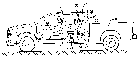
[0026] Figure 1 of the drawings appended hereto is a left side
elevational view of a stowable vehicle seat assembly according to
the invention, shown in use by a seat occupant in a deployed
design configuration inside a vehicle cabin, which vehicle cabin
has been cut-away for ease of illustration;
[0027] Figure 2 is an enlarged view of the dotted area 2 of
Figure 1, with the seat occupant removed for ease of illustration;
[0028] Figure 2A is an enlarged view of the dotted area 2A of
Figure 2;
[0029] Figure 3 is an enlarged view of the seat assembly of
Figure 1, shown in an unoccupiable fold-flatconfiguration with a
first storage space "B" shown in dotted outline;
[0030] Figure 3A is an enlarged view of the dotted area 3A of
Figure 3;
- 10 -
CA 02454590 2003-12-31
[0031] Figure 4 is an enlarged view of the seat assembly of
Figure 1, shown in an intermediate raised configuration;
[0032] Figure 4A is an enlarged view of the dotted area 4A of
Figure 4; and
[0033] Figure 5 is a view similar to Figure 3, with the seat
assembly shown in a raised stowed configuration with a second
storage space "H" shown in dotted outline.
DETAILED DESCRIPTION OF A PREFERRED ENBODIMENT
[0034] Referring now to Figures 1 through 5 of the drawings,
there is shown a stowable vehicle seat assembly 40 according to
the invention. As best seen in Figure 1, the seat assembly 40 is
particularly adapted for use in a vehicle 10 having a vehicle
cabin 12 such as may be found, for example, in a pick-up truck.
It should be noted, however, that although Figure 1 depicts the
seat assembly 40 in use as a second row seat in a pick-up truck,
the present invention is not so limited. In fact, the seat
assembly 40 of the present invention may also be advantageously
used in a second or subsequent row in mini-vans, sport utility
vehicles, or in any other vehicle in which it is desirable to
provide a cargo space within the vehicle cabin 12 that is easily
accessible through a side-facing door 13.
- 11 -
CA 02454590 2003-12-31
[0035] With specific reference to a preferred embodiment of the
invention that is depicted in Figures 1 through 5, it will be
appreciated that the seat assembly 40 is of the general type
having a backrest member 92 pivotally mounted on a seat cushion
member 42 for pivotal folding of the backrest member 92 relative
to the seat cushion member 42. As best seen in Figure 1,
cushioning and upholstery is provided in a conventional manner on
each of the backrest member 92 and the seat cushion member 42 to
support an occupant or user 30. As best seen in Figures 2 through
5, wherein the cushioning and upholstery of the seat cushion
member 42 are shown in partial section for simplicity of
presentation, a seat frame 44 is included within the seat cushion
member 42. It should perhaps be noted that, while the seat
assembly 40 according to the invention is described herein in use
with a cabin floor 14 of the vehicle cabin 12, neither the vehicle
cabin 12 nor the cabin floor 14 form a part of the invention.
Rather, they are referred to only as part of the cooperating
environment in which the present invention may be found to have
the greatest utility.
[0036] The seat frame 44 of the seat cushion member 42 is
preferably provided with two downwardly extending front legs 46
and two downwardly extending rear legs 48. The two front legs 46
are laterally offset from one another, so as to provide a
left-side front leg (as shown in each of Figures 1 through 5) and
a right-side front leg (not shown). Likewise, the two rear legs
48 are laterally offset from one another, so as to provide a
- 12 -
CA 02454590 2003-12-31
left-side rear leg (as shown in each of Figures 1 through 5) and
a right-side rear leg (not shown). Although the right-side front
and rear legs are not depicted in the accompanying figures, it
will be appreciated that they are substantial mirror-images of the
respective left-side counterparts that are visible in each of
Figures 1 through 5.
[0037] According to the invention, and as best seen in Figures
1, 3 and 5, the seat assembly 40 is provided with a control rod
system 82, pivotably interconnected between the cabin floor 14 and
the seat frame 44 of the seat cushion member 42, that is adapted
to enable selective rearward pivoting of the seat cushion member
42 from a deployed design configuration (as shown in Figures 1, 2
and 2A) towards a raised stowed configuration (as shown in Figure
5).
[0038] In the deployed design configuration shown in Figures 1,
2 and 2A, the seat cushion member 42 has a substantially
horizontal orientation and the backrest member 92 has a
substantially vertical orientation. As well, both the seat cushion
member 42 and the backrest member 92 are in substantially spaced
relation from a rear wall 28 of the vehicle cabin 12 in the
deployed design configuration.
[0039] Conversely, in the raised stowed configuration shown in
Figure 5, both the seat cushion member 42 and the backrest member
92 have a substantially vertical orientation. As well, the seat
- 13 -
CA 02454590 2006-10-20
cushion member 42 is in substantially adjacent parallel relation
with the rear wall 28, and the backrest member 92 is substantially
interposed between the seat cushion member 42 and the rear wall
28, in the raised stowed configuration.
[0040] According to the invention, and as best seen in Figure
2, the seat assembly 40 is also provided with a mounting means 54
positioned on the front legs 46 and on the rear legs 48 for
releasable engagement with the cabin floor 14. As best seen in
Figure 2A, the mounting means 54 includes two pivotably releasable
front locking hooks 56 mounted one each on each of the front legs
46, and two pivotably releasable rear locking hooks 60 mounted one
each on each of the rear legs 48. It is here noted that, although
front and rear locking hooks 56, 60 are shown in the accompanying
figures, it will be readily apparent to those skilled in the art
that any suitable alternate mounting means (not shown) may be used
according to the present invention. An example of one such
alternate mounting means is the arrangement disclosed in issued
U.S. Patent No. 5,626,391 (Miller et al.) for an Uptiltable Rear
Vehicle Seat Assembly, with only routine modifications that are
clearly within the scope of the invention disclosed herein being
necessary to be made to the structure and arrangement of
components of the seat assembly 40 described herein, so as to
accommodate such alternate mounting means.
-14-
CA 02454590 2003-12-31
[0041] In the deployed design configuration of the preferred
embodiment of the seat assembly 40 according to the present
invention, and as best seen in Figures 2 and 2A, each of the front
locking hooks 56 securely and releasably engages a respective
front striker pin 18 that is rigidly attached, by welding or the
like, to a respective front leg tub 16 defined within said cabin
floor 14. As well, in the deployed design configuration, each of
the rear locking hooks 60 securely and releasably engages a
respective rear striker pin 22 that is likewise rigidly attached
to a respective rear leg tub 20 defined within said cabin floor
14. Conversely, in the raised stowed configuration shown in
Figure 5, the locking hooks 56, 60 of the mounting means 54 are
each released from their aforesaid engagement with the respective
striker pins 18, 22 on the cabin floor 14.
[0042] As will be best appreciated from Figures 2 and 3, the
aforesaid secure mounting of the backrest member 92 on the seat
cushion member 42 is such that the backrest member 92 is
selectively foldable in a substantially forward folding direction
(as generally indicated by arrow "A") over the seat cushion member
42 from the deployed design configuration (shown in Figures 1, 2
and 2A) towards an unoccupiable fold-flat configuration (shown in
Figures 3 and 3A).
[0043] In the unoccupiable fold-flat configuration, the
backrest member 92 has a substantially horizontal orientation and
is in substantially parallel juxtaposed relation with the seat
- 15 -
CA 02454590 2003-12-31
cushion member 42. The backrest member 92 is provided with any
suitable backrest latching means to facilitate pivoting of the
backrest member 92, in the forward folding direction "A" about a
backrest pivot axis 95, over the seat cushion member 42 towards
the unoccupiable fold-flat configuration. In the preferred
embodiment shown in the figures, the backrest latching means is a
known rotary recliner mechanism 94 that operatively and pivotably
connects the backrest member 92 to the seat frame 44 in a
conventional manner, and wherein the inclination angle of the
backrest member 92 is easily adjustable to suit the comfort of the
occupant or user 30 through manual inclination manipulation of a
recliner handle (not shown). Such devices are well-known in the
art and for this reason they will not be described in significant
detail herein.
[0044] The unoccupiable fold-flat configuration shown in
Figures 3 and 3A is preferably intermediate of the deployed design
configuration and the raised stowed configuration (as shown in
Figure 5) . To this effect, the mounting means 54 is provided with
leg locking means 70 for preventing release of the mounting means
54 from the aforesaid engagement with the cabin floor 14, and for
preventing rearward pivoting of the seat cushion member 42 towards
the raised stowed configuration, unless the backrest member 92 is
in the aforesaid parallel juxtaposed relation with the seat
cushion member 42 that is reached in the unoccupiable fold-flat
configuration shown in Figures 3 and 3A.
- 16 -
CA 02454590 2003-12-31
[0045] According to this aspect of the invention, the leg
locking means 70 selectively releases the locking hooks 56, 60 of
the mounting means 54 from their engagement with the respective
striker pins 18, 22 on the cabin floor 14 when the backrest member
92 is in the unoccupiable fold-flat configuration. The leg
locking means 70 preferably includes a backrest link member 72
pivotally connected to the rotary recliner 94 of the backrest
member 92, and a hook pawl member 74 pivotally connected to the
backrest link member 72. The hook pawl member 74 is pivotable
about a pawl pivot pin 76 (best seen in Figure 2A). The backrest
link member 72 and the hook pawl member 74 are together adapted
for positive pivoting in unison with the backrest member 92
between the deployed design configuration (best seen in Figure 2A)
and the unoccupiable fold-flat configuration (best seen in Figure
3A).
[0046] With further reference to the mounting means 54, it will
be best appreciated from Figures 2A and 3A that each of the front
locking hooks 56 is adapted for pivoting in a substantially
forward opening direction (as generally indicated by arrow "C")
about a respective front hook pivot pin 58 - just as each of the
rear locking hooks 60 is adapted for pivoting in a substantially
forward opening direction (as generally indicated by arrow "D")
about a respective rear hook pivot pin 62 - between a closed
configuration (as shown in Figures 1, 2, 2A, 4, 4A and 5) and an
open configuration (as shown in Figures 3 and 3A). The mounting
means 54 is additionally provided with a hook link member 66,
- 17 -
CA 02454590 2003-12-31
preferably in the form of a rod member, that is operatively and
pivotally interconnected between the front locking hooks 56 and
the rear locking hooks 60, so as to cause positive pivoting of the
front locking hooks 56 in unison with positive pivoting of the
rear locking hooks 60 during pivoting between the closed
configuration and the open configuration as aforesaid.
[0047] In the deployed design configuration, and as best seen
in Figure 2A, a hook engaging surface 78 of the hook pawl member
74 engages a cam engaging surface 64 of the rear locking hooks 60
in obstructed relation so as to prevent pivoting of the rear
locking hooks 60 from the closed configuration towards the open
configuration. In the deployed design configuration, the hook
link member 66 (operatively connected to the obstructed rear
locking hooks 60) similarly prevents pivoting of the forward
locking hooks 56 from the closed configuration towards the open
configuration.
[0048] As such, in the unoccupiable fold-flat configuration
shown in Figures 3 and 3A, and indeed whenever the backrest member
92 is in the aforesaid parallel juxtaposed relation with the seat
cushion member 42, the hook pawl member 74 is removed from
engagement with the rear locking hooks 60, and the rear locking
hooks 60 are unobstructed by the hook pawl member 74, so as to
enable pivoting of the rear locking hooks 60 in unison with the
front locking hooks 56 from the closed configuration towards the
open configuration as aforesaid.
- 18 -
CA 02454590 2003-12-31
[0049] According to the preferred embodiment of the invention
illustrated, the front and rear locking hooks 56, 60 are biased in
a substantially rearward closing direction (as generally indicated
by arrow "F") towards the closed configuration. The rearward
closing direction "F" is substantially opposed to the forward
opening direction "D". Any suitable biasing means, such as, for
example, a torsion spring member (not shown) mounted about each of
the respective pivot pins 58 and 64, may be used to bias the front
and rear locking hooks 56, 60 towards the closed configuration as
aforesaid, as is well-known in the art.
[0050] As shown in Figures 2 through 3A, the mounting means 54
also includes a manually grippable handle means 68, operatively
connected to the front locking hooks 56, for pivoting the front
and rear locking hooks 56, 60 from the closed configuration (best
seen in Figures 2 and 2A) towards the open configuration (best
seen in Figure 3A). As depicted in Figure 1, the handle means 68
is rotatably mounted on the seat cushion member 42 about the pivot
pin 58. Selective pivoting of the handle means 68 in a
substantially upward handle direction (as generally indicated by
arrow "C" in each of Figures 2, 2A and 3A) actuates the aforesaid
pivoting of the front and rear locking hooks 56, 60.
[0051] According to the preferred embodiment of the invention,
and as best seen in Figure 4A, the seat assembly 40 is further
provided with backrest locking means 96 for locking the backrest
member 92 in the aforesaid substantially parallel juxtaposed
- 19 -
CA 02454590 2003-12-31
relation with the seat cushion member 42 when the mounting means
54 is released from its engagement with the cabin floor 14 as
aforesaid. To this effect, the backrest locking means 96
selectively obstructs the hook pawl member 74, and thus the
backrest member 92, from pivoting when the mounting means 54 is
released from its engagement with the cabin floor 14 as aforesaid.
The safety aspect of this arrangement will be readily apparent to
those skilled in the art as it prevents the seat assembly 40 from
being occupied whilst it is unlatched from the vehicle cabin floor
14.
[0052] According to this aspect of the invention, the backrest
locking means 96 is provided with a backrest cam member 98
connected substantially adjacent to the rear legs 60 for pivotal
rotation about a backrest cam pivot pin 100. The backrest locking
means 96 also includes a backrest cam biasing means 104 for
pivotally urging the backrest cam member 98 from a striker pin
engaging position (as shown in Figures 1 through 3A), in a
substantially upward camming direction (as generally indicated by
arrow "G" in Figures 4 and 4A) about the backrest cam pivot pin
100, towards a backrest engaging position (as shown in Figures 4,
4A and 5). Preferably, the backrest cam biasing means 104 is a
coil spring member interconnected between the backrest cam member
98 and an inner surface of the rear leg 48, but may take the form
of any suitable biasing means.
- 20 -
CA 02454590 2003-12-31
[0053] As best seen in Figures 2A and 3A, wherein the mounting
means 54 is depicted in engagement with the cabin floor 14 as
aforesaid, the backrest cam member 98 engages the rear striker pin
22 in the striker pin engaging position. Also, the hook pawl
member 74 is unobstructed by the backrest cam member 98 in the
striker pin engaging position, such that it may be selectively
pivoted in unison with the backrest member 92 between the deployed
design configuration and the unoccupiable fold-flat configuration
as aforesaid.
[0054] Conversely, and as best seen in Figure 4A wherein the
mounting means 54 is depicted as having been released from its
aforesaid engagement with the cabin floor 14, in the backrest
engaging position, the backrest cam member 98 is removed from its
aforesaid engagement with the rear striker pin 22 into operative
obstructing engagement with the hook pawl member 74, so as to lock
the backrest member 92 in its aforesaid substantially parallel
juxtaposed relation with the seat cushion member 42. In this
regard, it will be appreciated from Figure 4A that, when the
mounting means 54 is released from its engagement with the cabin
floor 14 as aforesaid, a backrest engaging surface 102 of the
backrest cam member 98 engages a cam engaging surface 80 of the
hook pawl member 74 in obstructed relation so as to prevent
pivoting of the hook pawl member 74, thus to prevent (with the
agency of the backrest link member 72) pivoting of the backrest
member 92 from its aforesaid substantially parallel juxtaposed
relation with the seat cushion member 42.
- 21 -
CA 02454590 2003-12-31
[0055] In the preferred embodiment shown in the figures, and as
best seen in Figures 1, 3 and 5, the control rod system 82 is
provided with a forward control rod 84 and a rearward control rod
86. The forward control rod 84 is pivotably interconnected
between a forward pivot pin 24 on the cabin floor 14 and a lower
pivot pin 50 on the seat frame 44. The rearward control rod 86 is
pivotably interconnected between a rearward pivot pin 26 on the
cabin floor 14 and an upper pivot pin 52 on the seat frame 44. As
such, the forward control rod 84, the rearward control rod 86, the
cabin floor 14 and said the seat frame 44 together define a
notional quadrilateral having four pivotal corners 24, 26, 50 and
52. It will be readily apparent to those skilled in the art that
this notional quadrilateral with its four pivotal corners 24, 26,
50 translate during movement of the seat cushion member 42 from
the deployed design configuration towards the raised stowed
configuration, as aforesaid, thereby causing the seat cushion
member 42 to positively pivot from the substantially horizontal
orientation towards the substantially vertical orientation.
[0056] In the preferred embodiment, the control rod system 82
of the seat assembly 40 is also provided with seat biasing means
88 for biasing the seat cushion member 42 towards the raised
stowed configuration. Preferably, the seat biasing means 88 is a
conventional torsion rod 90 pivotably interconnected between the
cabin floor 14 and the rearward control rod 86 substantially
adjacent to the rearward pivot pin 26.
- 22 -
CA 02454590 2003-12-31
[0057] In the preferred embodiment shown in the figures, and as
best seen in Figures 1, 3 and 5, the seat assembly 40 may also be
provided with stowed latching means 106 for releasably securing
the seat assembly 40 in the raised stowed configuration (as shown
in Figure 5). Preferably, the stowed latching means 106 includes
a locking hook 110 that is adapted to releasably and securely
engage the upper pivot pin 52 of the seat frame 44 when the seat
cushion member 42 reaches the raised stowed configuration (as best
seen in Figure 5), so as to be easily and conveniently locked in
the raised stowed configuration and so as to rigidly secure the
seat assembly 40 against pivotal movement upon forward and
rearward acceleration or deceleration of the vehicle 10.
Naturally, the stowed latching means 106 also includes a release
means 108 for releasing the locking hook 110 from its aforesaid
engagement with the upper pivot pin 52. Preferably, the release
means 110 of the stowed latching means 106 is both hand and foot
actuable, whilst also being effectively shielded from accidental
or inadvertent actuation.
[0058] In use, the seat assembly 40 is initially positioned in
the deployed design configuration shown in Figures 1 through 2A,
with the mounting means 54 releasably engaging the cabin floor 14.
The backrest member 92 may then be pivoted in the forward folding
direction "A" over the seat cushion member 42 to reach the
unoccupiable fold-flat configuration shown in Figures 3 and 3A,
and to provide a first storage space (as generally indicated by
dotted outline "B" in Figure 3) located upwardly of the folded
- 23 -
CA 02454590 2003-12-31
seat assembly 40. In the unoccupiable fold-flat configuration,
the rear locking hooks 60 are unobstructed by the hook pawl member
74, so as to enable selective pivoting of the handle means 68 in
the upward handle direction "C" and pivoting of the front and rear
locking hooks 56, 60 in the forward opening direction "D" from the
closed configuration towards the open configuration as aforesaid
(and as best seen in Figure 3A).
[0059] With the front and rear locking hooks 56, 60 in the open
configuration, the seat cushion member 42 is then pivoted in a
rearward stowing direction (as generally indicated by arrow "E" in
Figures 3, 4 and 5) from the unoccupiable fold-flat configuration
best seen in Figure 3, through an intermediate raised
configuration best seen in Figure 4, towards the raised stowed
configuration shown in Figure 5. When the mounting means 54 is
released from its engagement with the cabin floor 14, the front
and rear locking hooks 56, 60 are biased to move in the rearward
closing direction "F" from the open configuration towards the
closed configuration. Additionally, when the mounting means 54 is
released from its engagement with the cabin floor 14, the backrest
cam member 98 is biased to move in the upward camming direction
"G" from the striker pin engaging position towards the backrest
engaging position, so as to prevent pivoting of the backrest
member 92 from its substantially parallel juxtaposed relation with
the seat cushion member 42 as aforesaid.
- 24 -
CA 02454590 2003-12-31
[0060] On reaching the raised stowed configuration shown in
Figure 5, the seat assembly 40 is releasably secured by the stowed
latching means 106. The raised stowed configuration provides a
second storage space (as generally indicated by dotted outline "H"
in Figure 5) located forwardly of the seat assembly 40. It will
be appreciated that the seat assembly 40 according to the present
invention may be released from the stowed latching means 106 and
returned to the deployed design configuration by simply following
the aforesaid steps in reverse.
[0061] It will be appreciated from the foregoing that the seat
assembly 40 is relatively lightweight and quiet in use, and is
capable of fitting into a relatively small design envelope. It
also will be seen to have a simple design, with a correspondingly
low economy of manufacture, assembly, and installation. Thus, the
seat assembly 40 according to the present invention provides
adequate strength, durability and reliability and is easy to use,
with relatively little effort being required on the part of a user
30 in order to reach the raised stowed configuration. The raised
stowed configuration maximizes cargo space forwardly of the seat
assembly 40. As well, in its deployed design configuration, the
seat assembly 40 will be appreciated to be in spaced relation from
the rear wall 28 of the cabin 12 so as to provide additional cargo
volume and space necessary to adjust the angle of the seat's
backrest member 92 through manual inclination manipulation by the
user 30 of the recliner handle (not shown) that is conventionally
mounted outboard on the rotary recliner mechanism 94. It will be
- 25 -
CA 02454590 2003-12-31
further appreciated from the foregoing that the seat cushion
member 42 is selectively releasable from secure engagement with
the cabin floor 14 of the vehicle cabin 12 only when the seat
assembly 40 is in the unoccupiable fold-flat configuration. As
well, the handle means 68 of the invention is convenient to reach
and use in the unoccupiable fold-flat configuration.
[0062] Other modifications and alterations may be used in the
design and manufacture of the seat assembly 40 according to the
present invention without departing from the spirit and scope of
the invention, which is limited only by the accompanying claims.
For example, in the raised stowed configuration, the seat cushion
member 42 may not be in substantially adjacent parallel relation
with the rear wall 28. Likewise, the backrest member 92 may be
entirely absent from the assembly, and, if present, need not be
substantially interposed between the seat cushion member 42 and
the rear wall 28 in the raised stowed configuration. Further,
neither the backrest member 92 nor the seat cushion member 42 need
have a fully vertical orientation in the raised stowed
configuration, so long as the orientation in this configuration is
more vertical than horizontal. Additionally, the unoccupiable
fold-flat configuration need not be intermediate of the deployed
design configuration and the raised stowed configuration, but
rather folding of the backrest member 92 over the seat cushion
member 42 may be progressively coincident with rearward pivoting
of the seat cushion member 42 towards the raised stowed
configuration. In another example of a modification that lies
- 26 -
CA 02454590 2003-12-31
within the scope of the invention, the stowed latching means 106
may be other than in the form of the locking hook 110, and may
instead be in the form of a secure system of straps that
releasably secures the seat assembly 40 in the raised stowed
configuration. Similarly, either or both of the upward handle
direction "C" and the upward camming direction "G" may instead be
oriented in a substantially downward direction, or otherwise.
Likewise, one or more of the forward opening direction "D" and the
rearward closing direction "F" may be oriented in a direction
other than in a forward and rearward direction respectively.
Because of the numerous exemplary modifications of the seat
assembly 40 that are described above without departing from the
spirit and scope of the present invention, it is perhaps
worthwhile to once again note that the invention is limited only
by the accompanying claims.
- 27 -