Language selection

Search

Patent 2454948 Summary

Third-party information liability

Some of the information on this Web page has been provided by external sources. The Government of Canada is not responsible for the accuracy, reliability or currency of the information supplied by external sources. Users wishing to rely upon this information should consult directly with the source of the information. Content provided by external sources is not subject to official languages, privacy and accessibility requirements.

Claims and Abstract availability

Any discrepancies in the text and image of the Claims and Abstract are due to differing posting times. Text of the Claims and Abstract are posted:

  • At the time the application is open to public inspection;
  • At the time of issue of the patent (grant).
(12) Patent Application: (11) CA 2454948
(54) English Title: LABYRINTH LOCK SEAL FOR HYDROSTATICALLY SET PACKER
(54) French Title: JOINT DE VERROUILLAGE DE LABYRINTHE POUR GARNITURE DEFINIE HYDROSTATIQUEMENT
Status: Deemed Abandoned and Beyond the Period of Reinstatement - Pending Response to Notice of Disregarded Communication
Bibliographic Data
(51) International Patent Classification (IPC):
  • E21B 33/1295 (2006.01)
(72) Inventors :
  • KING, JAMES G. (United States of America)
  • WELCH, EDWARD W., JR. (United States of America)
(73) Owners :
  • BAKER HUGHES INCORPORATED
(71) Applicants :
  • BAKER HUGHES INCORPORATED (United States of America)
(74) Agent: MARKS & CLERK
(74) Associate agent:
(45) Issued:
(86) PCT Filing Date: 2002-07-19
(87) Open to Public Inspection: 2003-02-13
Examination requested: 2004-01-23
Availability of licence: N/A
Dedicated to the Public: N/A
(25) Language of filing: English

Patent Cooperation Treaty (PCT): Yes
(86) PCT Filing Number: PCT/US2002/022993
(87) International Publication Number: WO 2003012252
(85) National Entry: 2004-01-23

(30) Application Priority Data:
Application No. Country/Territory Date
09/916,985 (United States of America) 2001-07-27

Abstracts

English Abstract


A hydrostatically set packer is disclosed. The actuating piston (18) is locked
for run in by a lock sleeve (32) and lock dog (48) arrangement. When the
desired depth is reached well pressure is built up to break a rupture disc
(42) to allow hydrostatic pressure to act on one side of a lock sleeve. The
other side of the lock sleeve is exposed to a chamber (36) under atmospheric
or low pressure. Movement of the lock sleeve releases the lock dog allowing
piston movement to set the packer. The lock sleeve has a labyrinth seal (L) so
that seal leakage below a predetermined level will not prematurely activate
the piston lock and prematurely set the packer. A variety of designs for the
labyrinth are described-


French Abstract

L'invention concerne une garniture définie hydrostatiquement. Le piston de commande (18) est bloqué par un manchon de blocage (32) et un agencement taquet de blocage (48). Lorsque la profondeur souhaitée est atteinte, la pression du puits rompt un disque de rupture (42) afin de permettre à la pression hydrostatique d'agir sur un côté du manchon de blocage. L'autre côté du manchon de blocage est exposé à une chambre (36) sous pression atmosphérique ou sous faible pression. Le mouvement du manchon de blocage libère le taquet de blocage permettant au piston de se déplacer pour fixer la garniture. Le manchon de blocage présente un joint labyrinthe L de manière qu'une fuite inférieure à un niveau prédéterminé ne va pas actionner de manière prématurée le blocage du piston ni fixer prématurément la garniture. Une grande variété de motifs font également l'objet de cette invention.

Claims

Note: Claims are shown in the official language in which they were submitted.

We claim:
1. A downhole hydrostatically settable tool comprising:
a mandrel;
a piston mounted to said mandrel;
a moveable component actuated by said piston;
a slideably mounted lock assembly, for said piston, mounted to
an enclosure defined at least in part by said mandrel and selectively
movable in response to exposure of one part of said lock assembly in
said enclosure to downhole hydrostatic pressure;
said lock assembly further comprising a labyrinth seal mounted
to said lock assembly in said enclosure and allowing a leak flow
therethrough without allowing said piston to be unlocked.
2. The tool of claim 1, wherein:
said moveable component further comprises a gripping
assembly on said mandrel selectively actuated by said piston;
said lock assembly comprises an interior surface closest to said
mandrel and an outer surface; and
said labyrinth seal is disposed on said outer surface.
3. The tool of claim 1, wherein:
said lock assembly comprises an interior surface closest to said
mandrel and an outer surface; and
said labyrinth seal is disposed on said interior surface.
4. The tool of claim 1, wherein:
said labyrinth seal comprises a plurality of circumferential
grooves with adjacent grooves connected by at least one longitudinal
groove, said longitudinal grooves are offset from each other as
between adjacent circumferential grooves.
6

5. The tool of claim 1, wherein:
said labyrinth seal comprises a longitudinal bore extending
through said lock assembly.
6. The tool of claim 1, wherein:
said labyrinth seal comprises a longitudinal bore extending
through said lock assembly; and
a restrictor mounted in said bore.
7. The tool of claim 6, wherein:
said restrictor is removably mounted
8. The tool of claim 2, wherein:
said labyrinth seal comprises a plurality of circumferential
grooves with adjacent grooves connected by at least one longitudinal
groove, said longitudinal grooves are offset from each other as
between adjacent circumferential grooves.
9. The tool of claim 3, wherein:
said labyrinth seal comprises a plurality of circumferential
grooves with adjacent grooves connected by at least one longitudinal
groove, said longitudinal grooves are offset from each other as
between adjacent circumferential grooves.
10. A labyrinth seal for a downhole tool component, comprising:
a plurality of circumferential grooves with adjacent grooves
connected by at least one longitudinal groove, said longitudinal
grooves are offset from each other as between adjacent circumferential
grooves.
7

11. The labyrinth seal of claim 10, wherein:
said downhole component had an annular shape with an inside
and an outside surface and said grooves are disposed on said outside
surface.
12. The labyrinth seal of claim 10, wherein:
said downhole component had an annular shape with an inside
and an outside surface and said grooves are disposed on said inside
surface.
13. A labyrinth seal for a downhole tool component, comprising:
a longitudinal bore extending through said downhole
component.
14. The labyrinth seal of claim 13, further comprising:
a flow restrictor mounted in said bore.
15. The labyrinth seal of claim l4,wherein:
said flow restrictor is removably mounted.
16. The anchor or packer of claim l,further comprising:
a sealing assembly selectively actuated by said piston.
17. The anchor or packer of claim l6,further comprising:
a ratchet lock to hold said slips and said sealing assembly
outwardly from said mandrel after said piston has moved.
8

Description

Note: Descriptions are shown in the official language in which they were submitted.


CA 02454948 2004-O1-23
WO 03/012252 PCT/US02/22993
LABYRINTH LOCK SEAL FOR HYDROSTATICALLY SET PACKER
FIELD OF THE INVENTION
The field of this invention is labyrinth seal design as well as a particular
application to a lock for a hydrostatically set packer.
BACKGROUND OF THE INVENTION
Hydrostatically set devices for subterranean wells such as packers in the past
have relied on an initially locked piston. When the packer was placed at the
desired
depth, the locking mechanism was released, generally by pressurization of the
wellbore, or an electromechanical device or system. The electromechanical
devices
include, but are not limited to, systems that rely on acoustic, pressure
pulse, or
vibratory communication methods to enable the setting sequence of the packer
or
other downhole device. The applied wellbore pressure would break a rupture
disc to
expose the lock to hydrostatic pressure. In the embodiment of the
electromechanical
device, the device would expose the lock to hydrostatic pressure. Hydrostatic
pressure, acting on one side of the lock against an atmospheric chamber on the
other
side of the lock, allowed the lock to move. Release of the lock permits piston
movement. The piston moves due to the force of hydrostatic pressure across the
piston
which would set the slips and compress the seal against the borehole wall or
tubular,
or otherwise actuate the device. A lock ring would hold the set.
A potential problem with this known design was that seal leakage could allow
pressure to prematurely communicate to one side of the lock so that the packer
would
be prematurely unlocked and consequently, hydrostatically set. Thus, an
objective of
the present invention is to acknowledge that seal leakage is a potential
occurrence
with drastic and expensive consequences and to deal with that possibility. The
objective is met using a wide variety of labyrinth seals on the lock sleeve
assembly.
Even if leakage of the seals below a predetermined level were to occur, the
labyrinth
seal would prevent a net force from occurnng on the lock sleeve, thus
preventing
premature hydrostatic setting of the packer.
1

CA 02454948 2004-O1-23
WO 03/012252 PCT/US02/22993
Labyrinth seals have been used in different tools in downhole applications.
They have been used in perforating guns, as shown in U.S. Patents 4,886,126
and
5,680,905. They have been used in downhole turbo-machines, U.S. Patent
4,264,285
and in a fluid flow regulator, U. S. Patent 4,858,644. Hydraulically released
locks for
packers have been used in U.S. Patent 5,320,183.
U.5. Patent 5,720,349 shows the use of a labyrinth seal in an assembly of an
anchor, whipstock, and a starter mill. The labyrinth seal compensates for
thermal
expansion of a fluid filled system to prevent setting of the anchor due to
pressure that
would have otherwise built up due to thermal effects. This device is focused
on
compensation for pressure from thermal expansion. On the other hand, U.S.
Patent
5,689,905, in the context of a perforating gun, is focused on use of the
labyrinth seal
to prevent premature actuation of the gun due to seal leakage. Those skilled
in the art
will appreciate the scope of this invention from the description of the
preferred
embodiment, which appears below and the claims, which appear thereafter.
SUMMARY OF THE INVENTION
A hydrostatically set packer is disclosed. The actuating piston is locked for
run
in by a lock sleeve and lock dog arrangement. When the desired depth is
reached well
pressure is built up to break a rupture disc to allow hydrostatic pressure to
act on one
side of a lock sleeve. The other side of the lock sleeve is exposed to a
chamber under
atmospheric or low pressure. Movement of the lock sleeve releases the lock dog
allowing piston movement to set the packer. The lock sleeve has a labyrinth
seal so
that seal leakage below a predetermined level will not prematurely activate
the piston
lock and prematurely set the packer. A variety of designs for the labyrinth
are
described.
BRIEF DESCRIPTION OF THE DRAWINGS
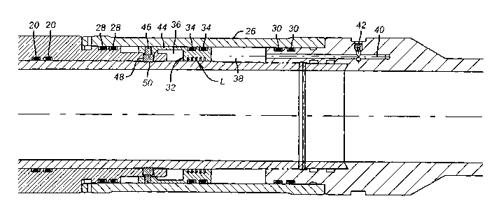
Figures la-le are a section view of a hydrostatically set packer with the
labyrinth seal on the lock sleeve for the actuating piston;
Figure 2 is a section view of the labyrinth seal shown in Fig. 1;
Figure 3 is an alternative embodiment of the labyrinth seal using a pinhole
leak path;
2

CA 02454948 2004-O1-23
WO 03/012252 PCT/US02/22993
Figure 4 is an alternative embodiment of the labyrinth seal showing the use of
a flow restrictor;
Figure 5 is the preferred embodiment of the labyrinth seal, showing it
externally mounted.
DETAILED DESCRIPTION OF THE PREFERRED EMBODIMENT
Refernng to Figs. la-le, the packer P of the invention has a top sub 10 used
to
secure a tubing string (not shown). The upper mandrel 12 is connected to top
sub 10.
The lower mandrel 14 is connected to the upper mandrel 12 and the bottom sub
16 is
below the lower mandrel 14. A piston 18 is mounted around the upper mandrel 12
and
lower mandrel 14 and with seal pairs 20 and 22 defines an atmospheric cavity
24. An
outer sleeve 26 is connected to bottom sub 16 at one end and extends to piston
18 at
the other end. Seal pairs 28 and 30 define an annular cavity in which the lock
sleeve
32 is disposed. Lock sleeve 32 has a seal pair 34 so as to create opposed
sealed
cavities 36 and 38 on opposed sides of lock sleeve 32. Bottom sub 16 has a
passage
40, which is initially blocked by a rupture disc 42. Passage 40 extends into
cavity 38.
Lock sleeve 32 has a cylindrical extension 44 with a shear pin 46 extending
into piston 18. Dog 48 is held into groove 50 by cylindrical extension 44.
Piston 18 is
trapped against movement until lock sleeve 32 has moved breaking the shear pin
46
and undermining the force holding the dog 48 in the groove 50. Since cavity 24
is at
atmospheric or low pressure, the net force to piston 18 moves it up against
lower slip
52, which in turn compresses seal assembly 54 and upper slip 56 against stop
58. A
lock ring 60 holds the set position.
In operation, the packer P is lowered to the desired position and pressure is'
built up to break the rupture disc. The burst pressure of the rupture disc 42
is set
higher than, the anticipated hydrostatic pressure anticipated at the setting
depth. Other
devices for allowing selective access into passage 40 can be alternatively
used. Once
the rupture disc is broken, pressure builds in cavity 38. Since cavity 36 is
at or close
to atmospheric pressure, the pressure buildup in cavity 38 moves the lock
sleeve and
the collet integral to it, up hole to break the shear pin 46 and to release
dog 48 from
groove 50. Now with the lock sleeve 32 abutting the piston 18, pressure in
cavity 38
also acts on piston 18. Since cavity 24 is at atmospheric there is little
resistance to the
3

CA 02454948 2004-O1-23
WO 03/012252 PCT/US02/22993
uphole movement of piston 18 and the packer P sets in the manner described
above.
This is the normal operation.
The present invention modifies the above-described design by an addition of a
labyrinth seal L to the lock sleeve 32. Various embodiments are illustrated in
Figs. 2-
5. The embodiment of Fig. 1d is shown in greater detail in Fig. 2. Grooves 62
and 64
retain seal pair 34 (not shown in Fig. 2). The tortuous path starts with
longitudinal
groove 66, which leads to circular groove 68. Flow must go 180 degrees to
reach
another longitudinal groove (not shown) to get into circular groove 70. From
there the
flow must go around 180 degrees to another longitudinal groove 72 and into
circular
groove 74. From there the flow is circumferential to another longitudinal
groove (not
shown) to groove 76. Thereafter, flow goes circumferentially to longitudinal
groove
78 and out into circular groove 80. Fig 5 is in essence the same design except
the
tortuous path is on the outside surface 82 rather than the inside surface 84.
Placing the
tortuous path on the outside is preferred because it simplifies the machining
of the
part.
In Fig. 3, grooves 62 and 64 are opposed by grooves 86 and 88 to
accommodate opposed seal pairs such as 34 (shown in Fig. 1d). The leak path 90
is
machined or cast into lock ring 32, depending how the part is produced.
Alternatively,
a commercially available restrictor, represented schematically by arrow 92 can
be
mounted in bore 94.
The advantage of using any of these versions or any others that allow a leak
rate of a predetermined value to occur without moving the lock sleeve 32 is
that
premature setting will not occur due to leakage up to a predetermined rate
past seals .
28 or 30. But for the labyrinth seal of the present invention leakage past
seal pairs 28
or 30 will force movement of lock sleeve 32 liberating piston 18 to move to
set the
packer P. Leakage of seals 20 or 22 will simply prevent piston 18 from moving
because no pressure differential exists once cavity 24 equalizes with the
downhole
environment. The packer P will not set if there is leakage around seals 34,
which is
sufficiently severe. If that happens, hydrostatic pressure will not be able to
put
sufficient differential pressure on lock sleeve 32 to move it to break shear
pin 46 and
liberate dog 48.
4

CA 02454948 2004-O1-23
WO 03/012252 PCT/US02/22993
Those skilled in the art will appreciate that if the hydrostatic pressure at
the
setting depth is too low, the packer P can be set with applied well pressure
into
passage 40 after breaking the rupture disc 42. Dissolving plugs or other
temporary
barriers or valves actuated from the tool or the surface can be used in place
of rupture
disc 42. The invention may be used on any downhole tool which has a
hydrostatically
set feature including a sleeve valve, ball valve, shifting mechanism, hole
punching
mechanism, pressure equalizing mechanism, tool or tool component deployment
mechanism, or other hydrostatically powered mechanism
It is to be understood that this disclosure is merely illustrative of the
presently
preferred embodiments of the invention and that no limitations are intended
other than
as described in the appended claims.
5

Representative Drawing
A single figure which represents the drawing illustrating the invention.
Administrative Status

2024-08-01:As part of the Next Generation Patents (NGP) transition, the Canadian Patents Database (CPD) now contains a more detailed Event History, which replicates the Event Log of our new back-office solution.

Please note that "Inactive:" events refers to events no longer in use in our new back-office solution.

For a clearer understanding of the status of the application/patent presented on this page, the site Disclaimer , as well as the definitions for Patent , Event History , Maintenance Fee  and Payment History  should be consulted.

Event History

Description Date
Time Limit for Reversal Expired 2006-07-19
Application Not Reinstated by Deadline 2006-07-19
Deemed Abandoned - Failure to Respond to Maintenance Fee Notice 2005-07-19
Amendment Received - Voluntary Amendment 2004-11-26
Letter Sent 2004-06-25
Inactive: Single transfer 2004-05-27
Inactive: Courtesy letter - Evidence 2004-03-23
Inactive: Cover page published 2004-03-18
Inactive: Acknowledgment of national entry - RFE 2004-03-16
Letter Sent 2004-03-16
Application Received - PCT 2004-02-23
Request for Examination Requirements Determined Compliant 2004-01-23
All Requirements for Examination Determined Compliant 2004-01-23
National Entry Requirements Determined Compliant 2004-01-23
Application Published (Open to Public Inspection) 2003-02-13

Abandonment History

Abandonment Date Reason Reinstatement Date
2005-07-19

Maintenance Fee

The last payment was received on 2004-01-23

Note : If the full payment has not been received on or before the date indicated, a further fee may be required which may be one of the following

  • the reinstatement fee;
  • the late payment fee; or
  • additional fee to reverse deemed expiry.

Please refer to the CIPO Patent Fees web page to see all current fee amounts.

Fee History

Fee Type Anniversary Year Due Date Paid Date
Registration of a document 2004-01-23
MF (application, 2nd anniv.) - standard 02 2004-07-19 2004-01-23
Request for examination - standard 2004-01-23
Basic national fee - standard 2004-01-23
Owners on Record

Note: Records showing the ownership history in alphabetical order.

Current Owners on Record
BAKER HUGHES INCORPORATED
Past Owners on Record
EDWARD W., JR. WELCH
JAMES G. KING
Past Owners that do not appear in the "Owners on Record" listing will appear in other documentation within the application.
Documents

To view selected files, please enter reCAPTCHA code :


To view images, click a link in the Document Description column. To download the documents, select one or more checkboxes in the first column and then click the "Download Selected in PDF format (Zip Archive)" or the "Download Selected as Single PDF" button.

List of published and non-published patent-specific documents on the CPD .

If you have any difficulty accessing content, you can call the Client Service Centre at 1-866-997-1936 or send them an e-mail at CIPO Client Service Centre.


Document
Description 
Date
(yyyy-mm-dd) 
Number of pages   Size of Image (KB) 
Description 2004-01-23 5 209
Claims 2004-01-23 3 78
Drawings 2004-01-23 7 115
Abstract 2004-01-23 1 63
Representative drawing 2004-01-23 1 24
Cover Page 2004-03-18 1 49
Acknowledgement of Request for Examination 2004-03-16 1 176
Notice of National Entry 2004-03-16 1 201
Courtesy - Certificate of registration (related document(s)) 2004-06-25 1 105
Courtesy - Abandonment Letter (Maintenance Fee) 2005-09-13 1 173
PCT 2004-01-23 6 231
Correspondence 2004-03-16 1 24