Language selection

Search

Patent 2455009 Summary

Third-party information liability

Some of the information on this Web page has been provided by external sources. The Government of Canada is not responsible for the accuracy, reliability or currency of the information supplied by external sources. Users wishing to rely upon this information should consult directly with the source of the information. Content provided by external sources is not subject to official languages, privacy and accessibility requirements.

Claims and Abstract availability

Any discrepancies in the text and image of the Claims and Abstract are due to differing posting times. Text of the Claims and Abstract are posted:

  • At the time the application is open to public inspection;
  • At the time of issue of the patent (grant).
(12) Patent Application: (11) CA 2455009
(54) English Title: SLIDER FOR ZIP FASTENER WITH TWO TABS AND A SINGLE FORK FOR RELEASING THE SLIDER
(54) French Title: CURSEUR DE FERMETURE A GLISSIERE AVEC DEUX PATTES ET UNE CHAPE POUR DEGAGER LE CURSEUR
Status: Deemed Abandoned and Beyond the Period of Reinstatement - Pending Response to Notice of Disregarded Communication
Bibliographic Data
(51) International Patent Classification (IPC):
  • A44B 19/26 (2006.01)
  • A44B 19/30 (2006.01)
(72) Inventors :
  • BERNASCONI, SERGIO (Switzerland)
(73) Owners :
  • RIRI GROUP S.A.
(71) Applicants :
  • RIRI S.A. (Switzerland)
(74) Agent: ROBIC AGENCE PI S.E.C./ROBIC IP AGENCY LP
(74) Associate agent:
(45) Issued:
(22) Filed Date: 2004-01-12
(41) Open to Public Inspection: 2005-04-28
Examination requested: 2008-12-11
Availability of licence: N/A
Dedicated to the Public: N/A
(25) Language of filing: English

Patent Cooperation Treaty (PCT): No

(30) Application Priority Data:
Application No. Country/Territory Date
01839/03 (Switzerland) 2003-10-28

Abstracts

English Abstract


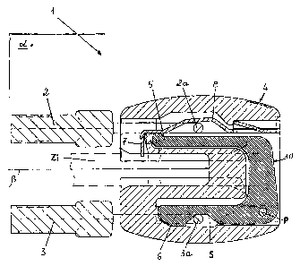
What is described is a slider (1) for zip fasteners
with two tabs (2,3), comprising a hollow body (4) in
which are positioned means (10, 5, 6) designed in such
a way that, when either one of the said two tabs (2,3)
is pulled, this causes the disengagement of a pawl (7)
from the teeth (Zi) of a fastener, overcoming the
resistance of elastic means (8,9) which keep the pawl
inserted between the said teeth (Zi). In the slider (1)
according to the invention, the said means consist of a
fork (10) provided with two prongs (5,6) positioned on
opposite sides of the plane (.beta.) of the teeth (Zi) and
pivoted at a point (P, Q) of the slider (1) in such a
way that it can rotate in a plane (.alpha.) perpendicular to
the said plane (.beta.) of the teeth (Zi) when a force is
exerted on at least one (6) of its prongs (5, 6) by
means of the tab (3) connected to it by its ring (3a).


Claims

Note: Claims are shown in the official language in which they were submitted.

-6-
CLAIMS
1. Slider (1, 11) for zip fasteners with two tabs (2,
3), comprising a hollow body (4) in which are
positioned means (10, 20, 5, 6, 15, 16) designed in
such a way that, when either one of the said two tabs
(2, 3) is pulled, this causes the disengagement of a
pawl (7, 17) from the teeth (Zi) of a fastener,
overcoming the resistance of elastic means (8, 9) which
keep the pawl inserted between the said teeth (Zi),
characterized in that the said means consist of a fork
(10, 20) provided with two prongs (5, 6, 15, 16)
positioned on opposite sides of the plane (.beta.) of the
aforesaid teeth (Zi) and pivoted at a point (P, Q) of
the slider (1, 11) in such a way that it can rotate in
a plane (.alpha.) perpendicular to the said plane (.beta.) of the
teeth (Zi) when a force is exerted on at least one (6,
16) of its prongs (5, 15, 6, 16) by means of the tab
(3) connected to it by its ring (3a).
2. Slider according to Claim 1, in which one (2) of
the two tabs (2, 3) is connected to an elastic strip
(8) terminating in the said pawl (7) in such a way that
it can disengage the pawl from the teeth (Zi), and the
other tab (3) is connected to a prong (6) of the fork
(10), the other prong (5) facing the said elastic strip
(8 ) in such a way that a rotation (R) of the fork (10)
caused by the aforesaid other tab (3) also causes the
said disengagement from the teeth (Zi) as a result of
the movement of the said other prong (5).
3. Slider according to Claim 1, in which the said
pawl (17) is formed on the free end (15t) of one (15)
of the said prongs (15, 16), an elastically
compressible spring (9) being inserted between the said
fork (20) and the hollow body (14) of the slider (11),
this spring keeping the pawl (17) inserted between the
teeth (Zi) of the fastener when no force is applied to
the fork (20), each of the said prongs (15, 16) being
connected to one of the two tabs (2, 3) by means of the
corresponding ring (2a, 3a) in such a way that, when

-7-
either one of the two tabs (2, 3) is pulled, the fork
(20) is made to rotate (O) in such a way that it causes
the disengagement of the pawl (17) from the teeth (Zi)
of the fastener.

Description

Note: Descriptions are shown in the official language in which they were submitted.


CA 02455009 2004-O1-12
Slider for zip fastener with taro tabs and a single fork
for releasing the slider
DESCRIPTION
The present invention relates to the field of what are
called "zip fasteners", in other words fasteners which
can be opened and closed by pulling on either one of
two tabs connected on opposite sides, by means of their
rings, to a slider, in other words to the member which
joins and disengages the teeth of the fastener.
An example of such a slider is described in the patent
EP 204 184 B1 held by YKK, and another example is
illustrated in Swiss patent application 01697/03 filed
by the present applicant.
In both of the said examples, the slider is locked in
its position by means of a pointed member which
penetrates between the teeth of the fastener, and in
order to move the slider it is first necessary to
disengage this member, which can also be called a
"pawl", from the teeth.
To ensure that this locking operation can be performed
by pulling as stated on either one of the two tabs
connected to the slider, the terminal rings of the tabs
are connected to two levers, located inside the hollow
body of the slider on opposite sides of the plane of
the fastener, and interconnected by contact or by means
of suitable return members. One of these levers is
connected integrally to the aforesaid pawl, and the
levers are designed and positioned in such a way that a
pull on either one of the two tabs will directly or
indirectly cause the movement of the said pawl in such
a way as to disengage it from the teeth of the
fastener.
The manufacture of the levers described above and of
the corresponding actuating systems entails production

CA 02455009 2004-O1-12
- 2 -
and assembly costs which, given the intrinsically
relatively low value of a slider with two tabs, have a
significant effect on the final cost.
Moreover, since an increase in the number of parts of
an assembly also increases the potential causes of
malfunction, the reliability of sliders made as
described above can sometimes be inadequate, and in
order to achieve correct operation it is necessary to
use more costly methods and materials, which in turn
have an additional effect on the price.
The inventor of the slider with two tabs according to
the present invention has devised a solution in which
the aforementioned two levers form a single piece, and
more specifically a single fork whose two prongs
perform the function of the said two levers. This fork,
connected by means of the aforesaid prongs to one of
the sliders and to the pawl described previously, is
pivoted within the hollow body of the slider, and is
shaped and positioned in such a way that, by pulling as
stated on either one of the two tabs, the user can act
on the pawl in such a way that it is disengaged from
the teeth of the fastener so that the slider can be
moved.
Like all sliders with two tabs, the slider according to
the invention, as described below, comprises elastic
means for keeping the pawl inserted between the teeth
of a fastener until, when the said prongs are acted on,
these means are deformed elastically to a sufficient
degree to disengage the pawl.
The object of t=he present invention is therefore a
slider for fasteners with two tabs as described in the
attached Claim 1.
Two examples of embodiment of the slider according to
the invention will now be described, with additional

CA 02455009 2004-O1-12
- 3 -
reference to the attached drawings, in which:
- Figure 1 is an enlarged longitudinal section
through a first example of embodiment of the
slider according to the invention, in which the
pawl does not form part of the said fork, and is
provided with an elastically flexible portion
which keeps it inserted between the teeth of a
fastener;
- Figure 2 is the same longitudinal section as that
shown in Fig. 1, in which the fork has been made
to rotate by a pull on the tab in the upper part
of the drawing, in such a way that the aforesaid
pawl is disengaged from the teeth of the fastener;
- Figure 3 is the same section as that shown in the
preceding figures, in which the pawl is disengaged
from the teeth of the fastener by a pull on the
tab in the lower part of the drawing;
- Figure 4 is the enlarged longitudinal section
through a second example of embodiment, in which
the pawl is formed integrally on the terminal part
of one of the prongs of the fork, and the elastic
means for returning the pawl to the position in
which it locks the slider consist of a spring
interposed between the fork and the hollow body of
the slider;
- Figure 5 is the same longitudinal section as that
shown in Fig. 4, in which the prong bearing the
pawl has been made to rotate, thus disengaging the
pawl, by means of the tab in the upper part of the
drawing;
- Figure 6 is the section shown in Figure 5, in
which the prong bearing the pawl has been made to
rotate by a pull on the other prong of the fork by
means of the tab in the lower part of the drawing.
With reference initially to Figures 1, 2, 3, these show
how, in a slider 1 with two tabs 2 and 3 according to
the invention, its hollow body 4 houses within it a
fork 10, pivoted at a point P of the slider and

CA 02455009 2004-O1-12
- 4 -
consisting of two prongs 5 and 6 positioned on opposite
sides of the plane ~i occupied by the teeth Zi of a
fastener (not all of which is shown). A flexibly
elastic strip 8 terminates in a pawl 7, and the strip 8
is shaped in such a way that, when no force is applied
to it, its pawl 7 is kept inserted between the said
teeth Zi to keep the slider 1 locked. The said strip 8
is positioned so that it faces and is parallel to one
prong 5 of the fork 10.
The tab 2 in the upper part of the drawing is connected
by its ring 2a to the said strip 8 in such a way that
pulling the tab (see Fig. 2) causes the pawl 7 to be
disengaged from the teeth Zi (arrow M).
The tab 3 in the lower part of the drawing is connected
by its ring 3a to the prong 6 in the lower part of the
drawing, and pulling this tab causes a rotation (arrow
R in Fig. 3) of the fork 10 about the said point P, in
a plane a perpendicular to the plane (3 of the teeth Zi,
which makes the prong 5 in the upper part of the
drawing, which is in contact with the strip 8, cause an
elastic deformation of the strip in this case also,
thus disengaging the pawl 7 from the teeth Zi (arrow
N).
It should be noted that, whereas the tab 2 in the upper
part of the drawing acts directly by -traction on the
strip 8, the tab 3 in the lower part of the drawing
acts on the said prong 6 by pressing with its ring 3a
on a surface with inclined planes S in such a way as to
cause the said rotation R of the fork 10.
This system of connection by means of inclined planes
is known to those skilled in the art.
Figure 4 shows another example of embodiment 11 of the
slider according to the invention. In this case also,
the slider 11 has a hollow body 14 in which is housed a

CA 02455009 2004-O1-12
- 5 -
fork 20 with two prongs 15 and 16, pivoted at a point Q
in such a way that it can rotate (arrow O, Figures 5
and 6) in a plane a perpendicular to the plane (3 of the
teeth Zi of the fastener (again not all of which is
shown) .
In this case, however, the said pawl 7 does not form
part of a separate member, but is formed integrally on
the free end 15t of a prong 15, which is drawn in the
upper part of the figure.
As shown in Figures 5 and 6, pulling on either one of
the two tabs 2 and 3 connected by their rings 2a and 3a
to the two prongs 15 and 16 makes the fork 20 rotate in
the direction of the said arrow 0, thus extracting
(arrow V) the aforesaid pawl 17 from the teeth Zi of
the fastener,
In this case, the elastic force which keeps the pawl 17
inserted between the said teeth Zi is provided by a
spring 9 interposed between the fork 20 and the hollow
body 4 of the slider 11, the spring being positioned
and designed in such a way as to oppose the said
rotation 0 of the fork 20.
In both embodiments described above, a slider 1, 11
according to the invention is provided, this slider
consisting of a smaller number of components and being
consequently more reliable and less expensive to
produce.

Representative Drawing
A single figure which represents the drawing illustrating the invention.
Administrative Status

2024-08-01:As part of the Next Generation Patents (NGP) transition, the Canadian Patents Database (CPD) now contains a more detailed Event History, which replicates the Event Log of our new back-office solution.

Please note that "Inactive:" events refers to events no longer in use in our new back-office solution.

For a clearer understanding of the status of the application/patent presented on this page, the site Disclaimer , as well as the definitions for Patent , Event History , Maintenance Fee  and Payment History  should be consulted.

Event History

Description Date
Application Not Reinstated by Deadline 2012-01-12
Time Limit for Reversal Expired 2012-01-12
Deemed Abandoned - Failure to Respond to Maintenance Fee Notice 2011-01-12
Inactive: Correspondence - MF 2010-08-10
Letter Sent 2009-01-27
Request for Examination Received 2008-12-11
Request for Examination Requirements Determined Compliant 2008-12-11
All Requirements for Examination Determined Compliant 2008-12-11
Letter Sent 2007-11-19
Letter Sent 2006-10-05
Inactive: IPC from MCD 2006-03-12
Application Published (Open to Public Inspection) 2005-04-28
Inactive: Cover page published 2005-04-27
Letter Sent 2004-04-29
Inactive: Single transfer 2004-04-01
Inactive: First IPC assigned 2004-03-12
Inactive: Courtesy letter - Evidence 2004-03-02
Inactive: Filing certificate - No RFE (English) 2004-02-23
Filing Requirements Determined Compliant 2004-02-23
Application Received - Regular National 2004-02-23

Abandonment History

Abandonment Date Reason Reinstatement Date
2011-01-12

Maintenance Fee

The last payment was received on 2010-01-06

Note : If the full payment has not been received on or before the date indicated, a further fee may be required which may be one of the following

  • the reinstatement fee;
  • the late payment fee; or
  • additional fee to reverse deemed expiry.

Please refer to the CIPO Patent Fees web page to see all current fee amounts.

Owners on Record

Note: Records showing the ownership history in alphabetical order.

Current Owners on Record
RIRI GROUP S.A.
Past Owners on Record
RIRI S.A.
SERGIO BERNASCONI
Past Owners that do not appear in the "Owners on Record" listing will appear in other documentation within the application.
Documents

To view selected files, please enter reCAPTCHA code :


To view images, click a link in the Document Description column. To download the documents, select one or more checkboxes in the first column and then click the "Download Selected in PDF format (Zip Archive)" or the "Download Selected as Single PDF" button.

List of published and non-published patent-specific documents on the CPD .

If you have any difficulty accessing content, you can call the Client Service Centre at 1-866-997-1936 or send them an e-mail at CIPO Client Service Centre.


Document
Description 
Date
(yyyy-mm-dd) 
Number of pages   Size of Image (KB) 
Abstract 2004-01-12 1 23
Description 2004-01-12 5 217
Claims 2004-01-12 2 55
Drawings 2004-01-12 6 238
Representative drawing 2004-05-17 1 22
Cover Page 2005-04-11 1 53
Filing Certificate (English) 2004-02-23 1 160
Courtesy - Certificate of registration (related document(s)) 2004-04-29 1 105
Courtesy - Certificate of registration (related document(s)) 2006-10-05 1 105
Courtesy - Certificate of registration (related document(s)) 2007-11-19 1 104
Reminder - Request for Examination 2008-09-15 1 118
Acknowledgement of Request for Examination 2009-01-27 1 176
Courtesy - Abandonment Letter (Maintenance Fee) 2011-03-09 1 173
Correspondence 2004-02-23 1 26
Fees 2004-12-30 1 29
Fees 2007-01-05 1 42
Fees 2008-01-04 1 43
Fees 2009-01-05 1 52
Fees 2010-01-06 1 52
Correspondence 2010-08-10 1 44
Correspondence 2011-03-09 1 95