Language selection

Search

Patent 2455105 Summary

Third-party information liability

Some of the information on this Web page has been provided by external sources. The Government of Canada is not responsible for the accuracy, reliability or currency of the information supplied by external sources. Users wishing to rely upon this information should consult directly with the source of the information. Content provided by external sources is not subject to official languages, privacy and accessibility requirements.

Claims and Abstract availability

Any discrepancies in the text and image of the Claims and Abstract are due to differing posting times. Text of the Claims and Abstract are posted:

  • At the time the application is open to public inspection;
  • At the time of issue of the patent (grant).
(12) Patent Application: (11) CA 2455105
(54) English Title: MOBILE COMPUTER TILTING ARRANGEMENT
(54) French Title: MECANISME D'INCLINAISON D'ORDINATEUR MOBILE
Status: Deemed Abandoned and Beyond the Period of Reinstatement - Pending Response to Notice of Disregarded Communication
Bibliographic Data
(51) International Patent Classification (IPC):
  • G06F 1/16 (2006.01)
(72) Inventors :
  • HUANG, CHAO-MING (Taiwan, Province of China)
  • WANG, WEN-CHIEH (Taiwan, Province of China)
  • CHUANG, CHIN-KU (Taiwan, Province of China)
(73) Owners :
  • TATUNG CO., LTD.
(71) Applicants :
  • TATUNG CO., LTD. (Taiwan, Province of China)
(74) Agent: SMART & BIGGAR LP
(74) Associate agent:
(45) Issued:
(22) Filed Date: 2004-01-09
(41) Open to Public Inspection: 2004-08-27
Examination requested: 2004-01-09
Availability of licence: N/A
Dedicated to the Public: N/A
(25) Language of filing: English

Patent Cooperation Treaty (PCT): No

(30) Application Priority Data:
Application No. Country/Territory Date
92203081 (Taiwan, Province of China) 2003-02-27

Abstracts

English Abstract


A mobile computer tilting arrangement is disclosed to include a
casing, the casing comprising at least two recessed locating holes
respectively disposed in at least two corners of the back side thereof, and
two plugs selectively detachably press-fitted into two of the at least two
recessed locating holes for supporting the casing on a flat surface in a
sloping position, each plug comprising a center through hole, and a pin
insertable into the center through hole to radially expand the respective
plug into friction engagement with one recessed locating hole of the
casing into which the respective plug is press-fitted.


Claims

Note: Claims are shown in the official language in which they were submitted.

WHAT IS CLAIMED IS:
1. A mobile computer tilting arrangement comprising:
a casing, said casing having a back side and at least two recessed
locating holes respectively disposed in at least two corners of said back
side; and
two plugs to be respectively press-fitted to two of said at least two
recessed locating holes adjacent to one same peripheral side of said
casing, said plugs each comprising a center through hole, and a pin
insertable into said center through hole to radially expand the respective
plug into friction engagement with one of said at least two recessed
locating holes of said casing into which the respective plug is press-fitted,
said pin having an outer diameter greater than an inner diameter of said
center through hole.
2. The mobile computer tilting arrangement as claimed in claim 1,
wherein said plugs comprising a head, wherein said head comprising a
bottom side and an upper surface.
3. The mobile computer tilting arrangement as claimed in claim 2,
wherein the bottom side of said head is stopped outside the back side of
said casing when the plug inserted into one of said at least two recessed
locating holes of said casing.
4. The mobile computer tilting arrangement as claimed in claim 2,
wherein said head comprising a recess on said upper surface of said head.
5. The mobile computer tilting arrangement as claimed in claim 4,
wherein said head further comprising a finger notch disposed in the upper
surface and connected to said recess.

6. The mobile computer tilting arrangement as claimed in claim 1,
wherein the outer surface of the shank of each of said plug is peripherally
ribbed.
7. The mobile computer tilting arrangement as claimed in claim 1,
wherein each of said plugs are respectively molded from rubber.
8. The mobile computer tilting arrangement as claimed in claim 1;
wherein said at least two recessed locating holes each are peripherally
ribbed on the wall inside.
9. The mobile computer tilting arrangement as claimed in claim 1,
wherein the pin of each of said plugs is respectively made from metal.
10. The mobile computer tilting arrangement as claimed in claim
1, wherein the pin of each of said plugs each further comprising a pull tab
at one end.
11. The mobile computer tilting arrangement as claimed in claim
10, wherein said pull tab is fastened pivotally with said end of said pin.
12. The mobile computer tilting arrangement as claimed in claim
10, wherein said pull tab is a pull ring.

Description

Note: Descriptions are shown in the official language in which they were submitted.


CA 02455105 2004-O1-09
MOBILE COMPUTER TILTING ARRANGEMENT
BACKGROUND OF THE INVENTION
1. Field of the Invention
The present invention relates to a mobile computer tilting
arrangement and, more particularly, to such a mobile computer tilting
arrange, which enables the mobile computer to be supported on the top of
a table in a tilting position.
2. Description of Related Art
The display module of a conventional mobile computer can only
be supported and W rued in one particular direction. Following fast
development of computer technology, the display window of a computer
can alternatively be changed between a longitudinal mode and a
transverse mode. Conventional fixed display support designs cannot
satisfy market requirements. Further, when a tablet PC (personal
computer) put on the top of a table, the light reflecting status of the
display screen may interfere with the working of the user.
Therefore, it is desirable to have a mobile computer tilting
arrangement that enables the mobile computer to be selectively
supported on a flat surface in longitudinally extended sloping position or
a transversely extended sloping position as desired.
SUMMARY OF THE INVENTION
It is the main object of the present invention to provide a mobile
computer tilting arrangement, which enables the mobile computer to be
longitudinally or transversely supported on a flat surface in a sloping
position as desired.
i

CA 02455105 2004-O1-09
To achieve these and other objects of the present invention, the mobile
computer tilting arrangement comprises a casing, and two plugs. The
casing comprise a back side, and at least two recessed locating holes
respectively disposed in at least two corners of the back side. The plugs
are selectively press-fitted to two of the at least two locating holes
adjacent to the same peripheral side for supporting the casing on a flat
surface in a sloping position. Each plug comprise a center through hole,
and a pin insertable into the center through hole to radially expand the
respective plug into friction engagement, within one recessed locating
hole of the casing into which the respective plug is press-fitted. The outer
diameter of the pin is slightly greater than the inner diameter of the center
through hole of each plug. The two plugs each comprise a head on one
end. The head of each plug comprising an upper side and a bottom side,
wherein the bottom side is stopped outside the back side of the casing
when the respective plug inserted into one recessed locating hole of the
casing. The pin is preferably made from metal, comprising a pull tab at
one end. The pull tab is preferably pivoted to the pin. Through the pull
tab, the pin can easily be disconnected from the respective plug, for
enabling the respective plug to be removed from the casing. By means of
changing the positioning of the plugs in the recessed locating holes of the
casing, the plugs can selectively support the casing on a flat surface in an
axially extended sloping position or a transversely extended sloping
position as desired. The plugs are molded from rubber or made from
suitable elastic material, each comprising a recess on the upper surface of
the head for receiving the pull tab of the respective pin in flush with the
2

CA 02455105 2004-O1-09
upper surface of the head of the corresponding plug, and a finger notch
through which the finger can be inserted to lift the pull tab. The pull tab
can be shaped like a ring, a triangular or rectangular frame, or any of a
variety of profiles. The shape of the recess fits the profile of the pull tab.
Other objects, advantages, and novel features of the invention
will become more apparent from the following detailed description when
taken in conjunction with the accompanying drawings.
BRIEF DESCRIPTION OF THE DRAWINGS
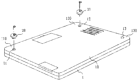
FIG 1 is a rearview of a casing of a mobile computer tilting
arrangement according to the preferred embodiment of the present
invention.
FIG. 2 is a schematic sectional view showing the installation of
one plug in one recessed locating hole of the casing according to the
present invention.
FIG. 3 is a schematic drawing showing the casing supported on
the top of a table in a sloping position.
DETAILED DESCRIPTION OF THE PREFERRED EMBODIMENT
Referring to FIG 1, a mobile computer tilting arrangement in
accordance with the present invention is shown comprising a casing 1 of
a mobile computer, and two elastic plugs 20 and 21. The casing 1 has a
back side 10, and three recessed locating holes 11,12, and 13 respectively
disposed in three corners 110,120, and 130 of the back side 10. The two
elastic plugs 20 and 21 are selectively press-fitted into two of the three
recessed locating holes 11,12, and 13 that are disposed adjacent to one
same peripheral side of the casing 1. Further, the elastic plugs 20 and Z1
3

CA 02455105 2004-O1-09
are preferably molded from rubber.
Referring to FIGS. 2 and 3, each plug 20 comprising a head 211,
a center through hole 212 axially piercing through the center of the plug
20 , a pin 213 inserted through the center through hole 212, and a pull tab,
for example, a pull ring 215 , which pivoted to one end of the pin 213.
The pin 213 is a cylindrical metal member comprising an outer diameter
d2 slightly greater than the inner diameter dl of the center through hole
212. When in use, the plug 20 is press-fitted into one of the recessed
locating holes 11, keeping the flat bottom side 214 of the head 211
stopped at the back side 10 of the casing 1 (see also FIG. 1 ), and then the
pin 213 is inserted into the center through hole 212 to expand the plug 20
radially and to force the peripherally ribbed outer surface 210 of the plug
shank into friction-engagement with the peripheral wall inside of the
corresponding recessed locating hole 11. After installation of two plugs
15 20,21 into any of the two recessed locating holes 11, 12, 13 neighboring
to one same peripheral side of the casing 1, the casing 1 of a mobile
computer can be supported on the top of a table in a tilting angle t (see
FIG. 3)
Referring to FIG. 2 again, the head 211 has a positioning recess
20 217 on the flat upper surface 216 where the pull ring 215 is kept in flush
with the flat upper surface 216 of the head 211. The head 211 further
comprising a finger notch 218 disposed in the flat upper surface 216 in
communication with the positioning recess 217. The user can insert the
finger into the finger notch 218 to lift the pull ring 215 and then to pull
the pin 213 out of the respective plug 20, enabling the respective plug
4

CA 02455105 2004-O1-09
20,21 to be removed from the corresponding recessed locating hole 11,
12,13.
Refernng to FIGS. 1~3 again, by means of selectively fastening
the two plugs 20,21 to any of two of the recessed locating hole 11, 12,
and 13, the plugs 20,21 can support the casing 1 of the mobile computer
in an axially tilted sloping position or transversely tilted sloping position.
Although the present invention has been explained in relation to
its preferred embodiments, it is to be understood that many other possible
modifications and variations can be made without departing from the
spirit and scope of the invention as hereinafter claimed.
s

Representative Drawing
A single figure which represents the drawing illustrating the invention.
Administrative Status

2024-08-01:As part of the Next Generation Patents (NGP) transition, the Canadian Patents Database (CPD) now contains a more detailed Event History, which replicates the Event Log of our new back-office solution.

Please note that "Inactive:" events refers to events no longer in use in our new back-office solution.

For a clearer understanding of the status of the application/patent presented on this page, the site Disclaimer , as well as the definitions for Patent , Event History , Maintenance Fee  and Payment History  should be consulted.

Event History

Description Date
Application Not Reinstated by Deadline 2008-11-03
Inactive: Dead - No reply to s.30(2) Rules requisition 2008-11-03
Deemed Abandoned - Failure to Respond to Maintenance Fee Notice 2008-01-09
Inactive: Abandoned - No reply to s.29 Rules requisition 2007-11-01
Inactive: Abandoned - No reply to s.30(2) Rules requisition 2007-11-01
Inactive: S.29 Rules - Examiner requisition 2007-05-01
Inactive: S.30(2) Rules - Examiner requisition 2007-05-01
Application Published (Open to Public Inspection) 2004-08-27
Inactive: Cover page published 2004-08-26
Inactive: First IPC assigned 2004-04-02
Filing Requirements Determined Compliant 2004-03-02
Inactive: Filing certificate - RFE (English) 2004-03-02
Letter Sent 2004-02-26
Application Received - Regular National 2004-02-23
Request for Examination Requirements Determined Compliant 2004-01-09
All Requirements for Examination Determined Compliant 2004-01-09

Abandonment History

Abandonment Date Reason Reinstatement Date
2008-01-09

Maintenance Fee

The last payment was received on 2006-10-12

Note : If the full payment has not been received on or before the date indicated, a further fee may be required which may be one of the following

  • the reinstatement fee;
  • the late payment fee; or
  • additional fee to reverse deemed expiry.

Please refer to the CIPO Patent Fees web page to see all current fee amounts.

Fee History

Fee Type Anniversary Year Due Date Paid Date
Application fee - standard 2004-01-09
Request for examination - standard 2004-01-09
Registration of a document 2004-01-09
MF (application, 2nd anniv.) - standard 02 2006-01-09 2005-10-11
MF (application, 3rd anniv.) - standard 03 2007-01-09 2006-10-12
Owners on Record

Note: Records showing the ownership history in alphabetical order.

Current Owners on Record
TATUNG CO., LTD.
Past Owners on Record
CHAO-MING HUANG
CHIN-KU CHUANG
WEN-CHIEH WANG
Past Owners that do not appear in the "Owners on Record" listing will appear in other documentation within the application.
Documents

To view selected files, please enter reCAPTCHA code :


To view images, click a link in the Document Description column. To download the documents, select one or more checkboxes in the first column and then click the "Download Selected in PDF format (Zip Archive)" or the "Download Selected as Single PDF" button.

List of published and non-published patent-specific documents on the CPD .

If you have any difficulty accessing content, you can call the Client Service Centre at 1-866-997-1936 or send them an e-mail at CIPO Client Service Centre.


Document
Description 
Date
(yyyy-mm-dd) 
Number of pages   Size of Image (KB) 
Abstract 2004-01-09 1 19
Description 2004-01-09 5 193
Claims 2004-01-09 2 68
Drawings 2004-01-09 3 38
Representative drawing 2004-05-06 1 10
Cover Page 2004-08-04 1 38
Acknowledgement of Request for Examination 2004-02-26 1 174
Courtesy - Certificate of registration (related document(s)) 2004-02-26 1 107
Filing Certificate (English) 2004-03-02 1 160
Reminder of maintenance fee due 2005-09-12 1 110
Courtesy - Abandonment Letter (Maintenance Fee) 2008-03-05 1 176
Courtesy - Abandonment Letter (R30(2)) 2008-01-10 1 167
Courtesy - Abandonment Letter (R29) 2008-01-10 1 167