Note: Descriptions are shown in the official language in which they were submitted.
CA 02455384 2007-07-19
PRECISE POSITION CONTROLLED ACTUATING METHOD AND SYSTEM
BACKGROUND OF THE INVENTION
[0002] The present invention relates to electro-mechanical actuators, and more
particularly, to devices for providing precisely controlled actuation of spray
pump
mechanisms.
[0003] The US Food and Drug Administration (FDA) strongly recommends automated
actuation of nasal spray devices subject to in-vitro bioequivalence testing to
decrease
variability in drug delivery due to operator factors (including removal of
potential analyst
bias in actuation) and increase the sensitivity for detecting potential
differences between
drug products. The FDA further recommends that an automated actuation system
has
settings or controls for actuation force, length of stroke, actuation
velocity, hold time,
return time, delay time between successive actuations, and actuation number.
Selection of
appropriate settings should be relevant to proper usage of the nasal aerosol
or nasal spray
by the trained patient, and should be documented based on exploratory studies
in which
actuation force, actuation time, and other relevant parameters are varied. One
such study
includes "Guidance for Industry: Bioavailability and Bioequivalence Studies
for Nasal
Aerosols and Nasal Sprays for Local Action," by
CA 02455384 2003-12-15
WO 2003/000429
PCT/US2002/019629
Wallace P. Adams, U.S. Department of Health and Human Services, Food and Drug
Administration, Center for Drug Evaluation and Research (CDER), June 1999.
[0004] Thorough characterization of the spray pump's performance in terms of
its
emitted spray pattern, plume geometry and/or droplet size distribution are
known to be
affected by the means in which the spray pump is actuated. For example, slow
actuation
will likely cause poor atomization, producing a stream-like flow. Fast
actuation will
likely cause too fine a spray to be produced, leading to poor absorption in
the nasal
mucosa and unwanted inhalation and deposition of the droplets in the throat
and lungs.
[0005] From a mechanical perspective, over-actuation (forcing the spray pump
assembly beyond its intended stopping point) of the spray pump device must be
avoided.
If the spray pump mechanism is over-actuated, permanent deformations can occur
to the
delicate pump orifice, swirl chambers and/or closure mechanisms, all of which
can
manifest themselves in higher than expected variability in the pump's spray
performance
and flow characteristics. Further, rigidly holding the nozzle of the spray
pump in place
during actuation is vital to ensure that the spray develops properly and exits
the nozzle
normally so that measurements of spray pattern, plume geometry and droplet
size
distribution are not artificially biased due to unwanted movement of the
nozzle.
[0006] The Innova Systems (Pennsauken, NJ) Nasal Spray Pump Actuators (NSP
and eNSP) are prior art automated nasal spray actuators. Both models use the
same
operating principle: a pneumatic cylinder connected to a solid plate (contact
plate) is
used to compress the spray pump against a spring loaded holding plate and clip
mechanism. Typically, these actuators are connected to a compressed air source
and a
computer interface to allow a user to set the actuation force, contact force,
holding time,
and dose time for the actuation event. In operation, these actuators adjust an
air pressure
regulator so that the pneumatic cylinder will first apply the prescribed
contact force to the
bottom side of the spray pump. Presumably, this application of the contact
force is done
to minimize the time delay in producing the spray and/or to prevent the
compression
plate from striking the spray pump with a dynamic load, which could damage the
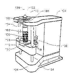
pump
due to the high dynamic forces achievable in the system. Next, the pressure
regulator is
adjusted again so that the pneumatic cylinder applies the prescribed actuation
force
2
CA 02455384 2003-12-15
WO 2003/000429
PCT/US2002/019629
(typically higher than the contact force). This action compresses the spray
pump at a rate
determined by the pneumatic efficiency of the system and the mechanical spring
resistance of the spray pump and fluid combination. The compression rate
cannot be
controlled. As a result, once the pressure regulator is set, the contact plate
will move at a
rate determined by the system, not the user.
[0007] Experience with using these actuators has shown the following
difficulties
and shortcomings:
1. Lack of position and velocity controls leads to uncontrolled, "air
hammer"-
like performance with substantial spray pump over-actuation. This
phenomenon has led to measurable degradation in spray pump performance
over time and larger than expected variations in delivered dosage content.
These problems are likely due to progressive deterioration in the moving
pump components due to over-actuation.
2. Lack of a nozzle holding mechanism leads to unwanted movements of the
nozzle during actuation. This causes artificial distortions and substantial
variability to appear in the associated spray pattern and plume geometry test
data.
3. Difficulties associated with pneumatic control lead to oscillating
contact
force application and this leads to pre-spray droplets forming on the nozzle
tip
and measurable variability in spray pattern, plume geometry, and droplet size
distribution data.
4. Reliance on variable quality, laboratory compressed air sources leads to
inconsistent actuation performance and potential safety issues.
5. Uncertain actuation event-time triggering causes difficulty in acquiring
time critical spray data such as spray pattern and plume geometry.
6. Uncertain applied force measurements do not give a user confidence that
the actuator is applying the desired force to the spray pump.
7. Absence of recordable applied force and/or position/velocity data make
it
difficult to chronicle the actuation event history.
3
CA 02455384 2003-12-15
WO 2003/000429
PCT/US2002/019629
SUMMARY OF THE INVENTION
[0008] In one aspect, a system for actuating a spray pump assembly including a
reservoir component and a pump/nozzle component comprises a reference
platform, a
motor component, a drive transmission component, a spray pump holder
component, a
force coupler, a force transducer, and a system controller. The reference
platform
provides a foundation upon which the components of the system are mounted. The
motor component is fixedly attached to the reference platform, receives a
power input
and a control input, and produces a rotary drive output therefrom. The drive
transmission component is fixedly attached to the reference platform, receives
the rotary
drive output and produces a linear drive output therefrom. The spray pump
holder
component is removably attached to the reference platform, and removably
secures the
spray pump assembly. The force coupler couples the linear drive output to the
spray
pump mechanism, so as to apply a force to the spray pump mechanism. The force
transducer produces a force signal proportional to the force applied to the
spray pump
mechanism. The system controller receives a set of test inputs including (i)
the force
signal, (ii) one or more feedback signals from the motor component, and (iii)
user input
corresponding to spray pump test parameters. The system controller provides
the control
input to the motor component as a predetermined function of the set of test
inputs. The
system is operative to actuate the spray pump mechanism according to an
actuation
profile defined by the set of test inputs.
[0009] In one embodiment, the motor component includes a servomotor. In
another embodiment, the servomotor includes a motor controller for receiving
and
processing the control input and for providing the one or more feedback
signals, and for
storing the actuation profile. The servomotor includes an encoder for
monitoring the
angular position of the rotary drive output and for producing an angular
position signal
corresponding to the angular position of the rotary drive output. The
servomotor further
includes a driver for receiving the actuation profile from the motor
controller and the
power input, and for producing a drive signal therefrom. The servomotor also
includes
an electric rotary motor for receiving the drive signal and for producing the
rotary drive
4
CA 02455384 2003-12-15
WO 2003/000429
PCT/US2002/019629
output therefrom.
[0010] In another embodiment, the motor component includes any one of a
variety of stepper motors known in the art.
[0011] In another embodiment, the actuation profile includes a quiescent
position
of the spray pump mechanism.
[0012] In another embodiment, the actuation profile includes a fully
actuated
position of the spray pump assembly.
[0013] In another embodiment, the actuation profile includes a velocity
profile
from a quiescent position of the spray pump assembly to a fully actuated
position of the
spray pump mechanism.
[0014] In another embodiment, the velocity profile includes velocity with
respect
to time.
[0015] In another embodiment, the actuation profile includes a force
profile from
a quiescent position of the spray pump mechanism to a fully actuated position
of the
spray pump mechanism.
[0016] In another embodiment, the force profile includes force with
respect to
time.
[0017] In another embodiment, the actuation profile includes a hold time
parameter corresponding to an amount of time the spray pump assembly is held
in a fully
actuated position.
[0018] In another embodiment, the drive transmission component includes at
least one linear screw-rail assembly.
[0019] In another embodiment, the at least one linear screw-rail assembly
includes an anti-backlash linear screw-rail assembly.
[0020] In another embodiment, the at least one linear screw-rail assembly
includes a low friction coating on at least a screw component within the
linear screw-rail
assembly.
[0021] In another embodiment, the low friction coating includes a Teflon-
based
material.
[0022] In another embodiment, the at least one linear screw-rail assembly
CA 02455384 2003-12-15
WO 2003/000429
PCT/US2002/019629
includes ball bearing supports for supporting a screw component within the
linear screw-
rail assembly.
[0023] Another embodiment further includes a first pulley fixedly
attached to the
rotary drive output, a second pulley fixedly attached to a screw component
within the
linear screw-rail assembly, and a drive belt for coupling the first pulley to
the second
pulley.
[0024] In another embodiment, the first pulley and the second pulley each
include a plurality of teeth, and the drive belt includes a plurality of ribs,
such that in
operation the teeth on the first pulley and the teeth on the second pulley
mesh with the
ribs on the drive belt.
[0025] In another embodiment, the rotary drive output is directly coupled
to the
drive transmission component.
[0026] In another embodiment, the spray pump holder component removably
secures the pump/nozzle component, and the coupler couples the linear drive
output to
the reservoir component.
[0027] In another embodiment, the spray pump holder component removably
secures the reservoir component, and the coupler couples the linear drive
output to the
pump/nozzle component.
[0028] In another embodiment, the force transducer is disposed between
the
spray pump assembly and linear drive output.
[0029] In another embodiment, the force transducer is disposed between
the
spray pump assembly and the spray pump holder component.
[0030] In another embodiment, the force transducer is disposed between
the
spray pump holder and the reference platform.
[0031] In another embodiment, the system controller includes a digital
acquisition assembly for sampling an angular position signal that
characterizes the
angular position of the rotary drive output, so as to generate one or more
digital samples
corresponding to the angular position signal. The system controller further
includes a
computer system that receives the set of test inputs and the one or more
digital samples,
generates the actuation profile and provides the actuation profile to the
motor component.
6
CA 02455384 2003-12-15
WO 2003/000429
PCT/US2002/019629
The computer system also receives the one or more feedback signals from the
motor
component and recording one or more physical parameters of the spray pump
assembly
during actuation.
[0032] In another embodiment, the one or more physical parameters of the
spray
pump assembly includes a position versus time profile that describes the
position of the
nozzle pump component with respect to the reservoir component as a function of
time.
[0033] In another embodiment, the one or more physical parameters of the
spray
pump assembly includes a force versus time profile that describes force
applied to the
nozzle pump component with respect to the reservoir component as a function of
time.
[0034] In another embodiment, the computer system performs a calibration
procedure, calculates one or more compensation values, and uses the
compensation
values to modify the one or more physical parameters.
[0035] In another embodiment, the computer system performs a calibration
procedure, calculates one or more compensation values, and uses the
compensation
values to modify the control input to the motor component.
[0036] In another embodiment, the system controller generates an
actuation
profile representative of a human hand actuating the spray pump assembly.
[0037] In another aspect, a method of actuating a spray pump via an
actuator
system comprises removably securing the spray pump assembly to a spray pump
holder
component. The method further comprises determining (i) a quiescent position
of the
spray pump, and (ii) a fully actuated position of the spray pump assembly. The
method
further comprises generating an actuation profile as a predetermined function
of the
quiescent position, the fully actuated position, and user input corresponding
to spray
pump test parameters. The method also comprises actuating the spray pump
according to
the actuation profile. The actuator system includes a rotary motor driving a
linear screw-
rail assembly, thereby applying a force to the spray pump assembly.
[0038] In another embodiment, the step of determining the quiescent
position of
the spray pump further includes measuring an amount of force applied to the
spray pump
assembly, and advancing the linear screw rail assembly until the amount of
force applied
to the spray pump assembly exceeds a first predetermined value. The step of
7
CA 02455384 2003-12-15
WO 2003/000429
PCT/US2002/019629
determining the quiescent position of the spray pump assembly also includes
recording a
position of the linear screw rail assembly when the amount of force applied to
the spray
pump assembly exceeds the first predetermined value.
[0039] In another embodiment, the step of determining the fully actuated
position
of the spray pump assembly further includes continuing to advance the linear
screw rail
assembly until the amount of force applied to the spray pump assembly exceeds
a second
predetermined value. The step of determining the fully actuated position of
the spray
pump assembly also includes recording a position of the linear screw rail
assembly when
the amount of force applied to the spray pump assembly exceeds the second
predetermined value.
[0040] In another aspect, a spray pump holder for securing a spray pump
assembly includes a clamp having an aperture disposed about a central axis,
and a
plurality of fingers disposed about the perimeter of the aperture and
extending out from
the clamp parallel to the central axis. The spray pump holder also includes a
compression member removably attached to the clamp. The pump/nozzle component
is
inserted into the aperture along the central axis, and the compression member,
when
attached to the clamp, compresses the plurality of fingers against the
pump/nozzle
component so as to secure the pump/nozzle component to the clamp.
[0041] In another embodiment, the clamp consists of a low friction
material. In
one embodiment, the low friction material is Teflon.
[0042] In another embodiment, the compression member is constructed and
arranged so as to variably compress the plurality of fingers against the
pump/nozzle
component.
[0043] In another embodiment, the clamp and the compression member
include
mating threads, such that the compression member screws into the clamp and
drives the
fingers toward the central axis. In one embodiment, the compression member
consists of
anodized aluminum.
[0044] Another embodiment of the spray pump holder further includes an
annular
insert disposed about the central axis, between the fingers and the central
axis. The
pump/nozzle component is inserted through the annular insert and the fingers
compress
8
CA 02455384 2003-12-15
WO 2003/000429
PCT/US2002/019629
the annular insert against the pump/nozzle component. In another embodiment,
each of
the fingers is characterized by a triangular cross section in a plane
perpendicular to the
central axis.
[0045] In another embodiment, the clamp is characterized by a
substantially
square body, disposed within a plane that is perpendicular to the central
axis. In another
embodiment, opposite sides of the square body slide into, or otherwise engage,
corresponding grooves in a reference platform.
[0046] In another aspect, a spray pump holder for securing a spray pump
assembly comprises a bracket for supporting the spray pump assembly, and at
least one
securing strap for removably securing the spray pump assembly against the
bracket.
[0047] In another embodiment, the bracket includes a first cradle member
having
a first engaging surface for retaining a first surface of the reservoir
component, and a
second cradle member having a second engaging surface for retaining a second
surface of
the reservoir component.
[0048] In another embodiment, the first engaging surface is substantially
orthogonal to the second engaging surface.
[0049] In another embodiment, the first engaging surface includes a V-
shaped
surface, so that the first engaging surface contacts a reservoir component
having an
arcuate exterior surface at two locations.
[0050] In another embodiment, the second engaging surface includes a V-
shaped
surface, so that the second engaging surface contacts a reservoir component
having an
arcuate exterior surface at two locations.
[0051] In another embodiment, the bracket further includes an aperture,
disposed
between the first cradle member and the second cradle member, for
accommodating a
heel portion of the spray pump assembly.
[0052] Another embodiment of the spray pump holder further includes a
first
securing strap and a second securing strap. The first securing strap secures
the spray
pump assembly against the first cradle member, and the second securing strap
secures the
heel portion of the spray pump assembly into the aperture and against the
second cradle
member. In one embodiment of the spray pump holder, a first end of the at
least one
9
CA 02455384 2011-06-14
securing strap is removably attached to a second anchor on the bracket.
[0053] In another embodiment, the second end of the at least one securing
strap
loops around the second anchor removably attaches to a distal portion of the
securing
strap.
[0054] In another aspect, a spray pump holder for securing a spray pump
assembly comprises a base including a body member, and a housing member having
a
stop tab. The spray pump holder further includes a clamping assembly including
a first
lever and a second lever pivotally attached at a pivot point about a pivot
axle. The spray
pump holder also includes a spring attached to the first lever and the second
lever so as
to force together a first end of the first lever and a first end of the second
lever. The
stop tab provides a platform or buttress, against which a pump/nozzle
component of a
spray pump assembly presses, and the pump/nozzle component is secured between
the
first end of the first lever and a first end of the second lever.
[0055] In another embodiment, the body member is characterized by a square
body, and opposite sides of the square body slide into corresponding grooves
in a
reference platform.
[0055a] In another embodiment, a system for actuating a spray pump
assembly, the system comprising: a motor component for receiving a power input
and a
control input and producing a rotary drive output therefrom; a drive
transmission
component for receiving the rotary drive output and producing a linear drive
output
therefrom; a spray pump holder component for removably securing the spray pump
assembly; a force coupler for coupling the linear drive output to the spray
pump
mechanism, so as to apply a force to the spray pump mechanism; a force
transducer for
producing a force signal proportional to the force applied to the spray pump
mechanism; and a system controller for receiving a set of test inputs
including (i) the
force signal, (ii) one or more feedback signals from the motor component, and
(iii) user
input corresponding to spray pump test parameters, and providing the control
input to
the motor component as a predetermined function of the set of test inputs;
wherein the
system is operative to actuate the spray pump mechanism according to an
actuation
profile defined by the set of test inputs.
CA 02455384 2011-06-14
BRIEF DESCRIPTION OF THE DRAWINGS
[0056] The foregoing and other objects of this invention, the various
features
thereof, as well as the invention itself, may be more fully understood from
the
following description, when read together with the accompanying drawings in
which:
[0057] FIG. 1 shows a block diagram view of one preferred embodiment of a
system for providing precisely controlled actuation of spray pump assembly;
[0058] FIG. 2A shows a nasal spray pump assembly in the quiescent
position;
[0059] FIG. 2B shows a nasal spray pump assembly in the fully actuated
position;
[0060] FIG. 2C shows an MDI spray pump assembly in the quiescent position;
[0061] FIG. 2D shows an MDI spray pump assembly in the fully actuated
position;
[0062] FIG. 3A shows a perspective view of one embodiment of the actuator
system
[0063] FIG. 3B is a sectional view of the system of FIG. 3A;
[0064] FIG. 3C is a bottom view of the system of FIG. 3A;
[0065] FIG. 4A shows the constituent pieces of the spray pump holder
component of the embodiment shown in FIG. 3A;
[0066] FIG. 4B shows a perspective view of the assembled spray pump holder
component secured to a spray pump assembly of FIG. 3A;
[0067] FIG. 5A is a perspective view of an MDI spray pump actuator;
[0068] FIG. 5B is a side sectional view of the embodiment of FIG. 5A;
[0069] FIG. 6A shows a perspective view of an MDI spray pump holder for
the
embodiment of FIG. 5A;
[0070] FIG. 6B shows an exploded view of the MDI spray pump holder of FIG.
6A;
[0071] FIG. 6C shows the spray pump holder securing the MDI spray pump
assembly of FIG. 6A;
[0072] FIG. 7A illustrates one example of an oral spray pump assembly;
[0073] FIG. 7B shows a perspective view of an alternate spray pump holder
assembly secured to the oral spray pump assembly of FIG. 7A; and,
10a
CA 02455384 2011-06-14
[0074] FIG. 7C shows an exploded view of the alternate spray pump holder
assembly of FIG. 7B.
DESCRIPTION OF THE PREFERRED EMBODIMENTS
[0075] FIG. 1 shows a block diagram view of one preferred embodiment of
an
actuator system 100 for providing precisely controlled actuation of spray pump
assembly
102. The system includes a reference platform 104, a motor component 106, a
drive
transmission component 108, a spray pump holder component 110, a force
transducer 112,
and a system controller 114. The reference platform 104 provides a
substantially rigid
platform upon which the various components of the actuator system 100 may be
mounted,
11
CA 02455384 2003-12-15
WO 2003/000429
PCT/US2002/019629
and provides a fixed reference from which the other components may relate to
one
another.
[0076] In general, the spray pump assembly 102 consists of two cooperative
components, and emits a spray plume when an applied force moves the two
cooperative
components relative to one another. In one embodiment the spray pump assembly
102
includes a reservoir component 120 and a pump/nozzle component 122, as shown
in FIG.
2A and FIG. 2B. FIG. 2A shows the spray pump assembly102 in the quiescent
position,
and FIG. 2B shows the spray pump assembly 102 in the fully actuated position.
The
spray pump assembly shown in FIGs. 2A and 2B is generally known in the art as
a nasal
spray pump assembly. The nasal spray pump emits a spray plume 124 when the
assembly transitions from the quiescent position to the fully actuated
position, and
automatically returns to the quiescent position. Another embodiment of the
system 100
may be used to actuate another type of spray pump assembly generally known as
a
metered dose inhaler (referred to herein as "MDI"), as shown in FIGs. 2C and
2D.
Although the mechanics of the nasal spray pump assembly and the MDI differ
significantly, the two cooperative components of the MDI will be referred to
herein as
the reservoir component 120 and the pump/nozzle component 122 as shown in
FIGs. 2C
and 2D for explanatory purposes only. Thus, FIG. 2C shows the spray pump
assembly
102 in the quiescent position, and FIG. 2D shows the spray pump assembly 102
in the
fully actuated position. The MDI emits a spray plume 124 when the assembly
transitions
from the quiescent position to the fully actuated position, and automatically
returns to the
quiescent position
[0077] The motor component 106 is mounted to the reference platform 104,
receives a power input from an external power source (not shown) and a control
input
from the system controller 114, and produces a rotary drive output dependent
on the
power and control inputs. In one embodiment, the rotary drive output consists
of a
cylindrical shaft rotating about an axis of rotation, and may be
instantaneously
characterized by an angular position, an angular velocity, an angular
acceleration and a
torque. The rotary drive output may include rotation in either direction
(i.e., clockwise
or counterclockwise), and may include an angular velocity of zero (i.e., at
rest -- not
12
CA 02455384 2003-12-15
WO 2003/000429
PCT/US2002/019629
rotating).
[0078] The drive transmission component 108 is also mounted to the reference
platform 104 and receives the rotary drive output from the motor component
106. The
drive transmission component 108 transforms the rotational motion of the
rotary drive
output into linear motion, so as to produce a linear drive output. In one
embodiment, the
linear drive output consists of a shaft traveling along a linear axis. In
another
embodiment, the linear drive output consists of a nut assembly traveling on a
screw-rail
along a linear axis. The linear drive output may be instantaneously
characterized by a
linear position, a linear velocity, a linear acceleration and a linear force.
The linear drive
output may include translation in either direction along the linear axis, and
may include a
linear velocity of zero (i.e., at rest -- not moving).
[0079] The spray pump holder 110 is removably attached to the reference
platform
104 so that the spray pump holder 110 is held stationary with respect to the
reference
platform 104 during system operation, but can be removed and repositioned with
relative
ease (i.e., without special tools or significant effort). The spray pump
holder 110 is
attached to the reference platform 104 using any of a variety of techniques
known in the
art, including but not limited to a friction engagement (e.g., press fit), a
threaded
engagement (e.g., screw threads into a tapped aperture), a keyed latch fit,
etc. Similarly,
the spray pump holder 110 removably secures the spray pump assembly 102.
During
operation, the spray pump assembly 102 is held stationary with respect to the
reference
platform 104 during system operation, but can be removed and repositioned, or
swapped
with an alternate spray pump assembly with relative ease.
[0080] The linear drive output from the drive transmission component 108 is
coupled to the spray pump assembly 102 via a "force coupler," so that during
operation,
the linear drive output applies a force to the spray pump assembly 102. In one
embodiment, this force coupler consists of a direct physical connection
between the
linear drive output and the spray pump assembly 102. In other embodiments, the
coupling includes a linkage between the linear drive output and the spray pump
assembly
102, such as a mechanical linkage, pneumatic linkage, hydraulic linkage, or
other similar
linkage, to redirect or otherwise condition the linear drive output.
13
CA 02455384 2003-12-15
WO 2003/000429
PCT/US2002/019629
[0081] The force transducer 112 produces a force signal that is
proportional to the
amount of force delivered to the spray pump assembly 102, and provides the
force signal
to the system controller 114 and the motor component 106. The motor component
106
uses the force signal to detect destructive force levels on the spray pump
assembly 102.
The motor component 106 compares the force signal to a predetermined threshold
value,
and reduces or eliminates the forces prior to damaging the spray pump assembly
102. In
the embodiment shown in FIG. 1, the force transducer 112 is situated between
the linear
drive output and the spray pump assembly 102. Other embodiments of the system
100
may incorporate the force transducer 112 between the spray pump assembly 102
and the
spray pump holder 110, or between the spray pump holder 110 and the reference
platform. In general, the force transducer 112 may be situated anywhere that
results in a
force signal that is proportional to the amount of force delivered to the
spray pump
assembly 102.
[0082] The system controller 114 is electrically coupled to the motor
component
106 and the force transducer 112. The system controller 114 receives the force
signal
from the force transducer 112 and feedback signals from the motor component
106.
Among other data, the feedback signals from the motor component 106 provide
information to the system controller 114 regarding the angular position of the
rotary
drive output. The system controller 114 also receives user input data that in
part defines
the desired actuation profile to which the spray pump assembly is to be
subjected. The
actuation profile includes, but is not limited to, actuation velocity,
actuation acceleration,
initial actuation delay, actuation hold time, post-actuation delay, number of
iterative
actuations, among others. Further, one unique actuation profile may be used
for the
upstroke (i.e., from quiescent position to fully-actuated position) and
another unique
actuation profile for the down-stroke (i.e., from the fully-actuated position
to the
quiescent position). The system controller 114 also measures and records a
plurality of
pump stroke statistics, including, but not limited to, distance required to
achieve
maximum velocity, distance at maximum velocity, distance required to stop from
maximum velocity, time required to achieve maximum velocity, time spent while
at
maximum velocity, time required to stop from maximum velocity, time required
to reach
14
CA 02455384 2003-12-15
WO 2003/000429
PCT/US2002/019629
the fully-actuated position, total time required for overall actuation, among
others.
[0083] Another embodiment of the system 100 described in FIG. 1 is shown in
FIGs. 3A, 3B and 3C. FIG. 3A shows a perspective view of the system 100
(without the
system controller 114), FIG. 3B is a sectional view of the system 100, showing
internal
components hidden by the shroud 138 in FIG. 3A, and FIG. 3C is a bottom view
of the
system 100. This embodiment includes a reference platform 104, a motor
component
106, a drive transmission component 108 (also referred to in this embodiment
as a "linear
screw-rail assembly"), a spray pump holder component 110, a force transducer
112, a
force coupler 130 (also referred to in this embodiment as a" compression
plate"), a drive
coupler 132, two guide rods 134, and system controller 114. The interaction of
these
components is the same as for similarly numbered components in FIG. 1;
however, this
embodiment includes several components not shown in FIG. 1. The compression
plate
130 couples the force generated by the linear drive output to the spray pump
assembly
102. The compression plate 130 travels along two guide rods 134 that are
fixedly
attached to the reference platform 104 and are parallel to the spray axis 136.
Thus, the
direction of travel of the compression plate 130 is parallel to the spray axis
136. The
drive coupler 132 includes two pulleys and a drive belt. One of the pulleys is
fixedly
attached to the rotary drive output of the motor component 106 (i.e., the
motor spindle),
so that the pulley rotates along with the motor spindle. The other pulley is
fixedly
attached to the screw-rail spindle of the linear screw-rail assembly 108, so
that the pulley
rotates along with the screw-rail spindle. The drive belt couples the two
pulleys so that
the two pulleys rotate synchronously. In one embodiment, the pulleys have
teeth or
similar frictional ribs that correspond to teeth or frictional ribs on the
drive belt, so that in
operation the drive belt meshes with the pulleys to reduce or prevent
slippage. In other
embodiments, the drive coupler 132 may include gears rather than pulleys, and
a drive
chain rather than a drive belt, or other similar techniques known in the art
for coupling
rotational motion.
[0084] FIG. 4A shows the constituent pieces of the spray pump holder component
110 of the embodiment shown in FIG. 3A, including a clamp 150, a compression
member 152, and several annular inserts 154. FIG. 4B shows a perspective view
of the
CA 02455384 2003-12-15
WO 2003/000429
PCT/US2002/019629
assembled spray pump holder component 110 secured to a spray pump assembly
102.
The clamp 150 includes a square body 155, and an aperture 156 disposed about a
central
axis 158, through which the pump/nozzle component of the spray pump assembly
is
inserted. The clamp 150 also includes a plurality of fingers 160 disposed
about the
perimeter of the aperture 156. The fingers 160 are characterized by a
triangular cross-
section in the plane perpendicular to the central axis, and extend out from
the clamp 150
in a direction parallel to the central axis 158, as shown in FIG. 4. In one
embodiment,
the clamp 150 is made of Teflon, although other similar low-friction materials
(e.g.,
plastic, composite materials, or a rigid material coated with a low-friction
material) may
also be used. The compression member 152 includes a disc-shaped body having an
aperture 162 arranged such that an interior surface 164 of the compression
member 152
is slightly conical. In one embodiment the compression member 152 is made of
anodized aluminum, although other similar materials (e.g., plastic, steel, and
other rigid
metals and composite materials) may also be used. The compression member 152
engages the clamp 150 via mating threads 166, so that the compression member
152 can
be screwed into the clamp 150. As the compression member 152 so engages the
clamp
150, the interior conical surface 164 of the compression member 152 compresses
the
fingers 160 inward toward central axis 158 and against the pump/nozzle
component. In
one embodiment, the spray pump holder component 110 also includes an annular
insert
154 disposed about the central axis 158 between the fingers 160 and the
central axis 158,
so that the pump/nozzle component is inserted through the annular insert 154.
In
operation, the fingers 160 compress the annular insert 154 against the
pump/nozzle
component. The square body 155 of the spray pump holder component 110 is
inserted
into mating grooves 168 in the reference platform 104 (see FIG. 3A). The
entire
holder/spray pump assembly can thus be rotated along the spray axis in 90
degree
increments to allow different orientations of the emitted spray to be viewed
by associated
spray characterization equipment.
[0085] In operation, a spray pump assembly 102 is inserted into the spray pump
holder component 110 and placed in the chassis so that the movement of the
pump
compression plate 130 is in line with the spray axis 136 of the spray pump
assembly 102.
16
CA 02455384 2003-12-15
WO 2003/000429
PCT/US2002/019629
The compression plate 130 moves along the guide rods 134 in the direction of
the spray
axis 136, driven by the rotation of the coupled motor and linear screw-rail
spindles. The
spray pump holder component 110 holds the pump/nozzle component 122 stationary
with respect to the reference platform 104, and the compression plate 130
moves the
reservoir component 120 with respect to the pump/nozzle component 122 to
actuate the
spray pump assembly 102.
[0086] The force transducer 112 is mounted within the compression plate 130 to
measure the force applied to the pump by the movement of the compression plate
130.
One embodiment includes a separate contact plate 138, situated over the force
transducer
112, that makes contact with the spray pump assembly 102 during actuation. In
such
embodiments the force transducer 112 is "sandwiched" between the contact plate
and the
compression plate 130. In addition, the pump contact plate of the present
invention is
bolted to the top face of the force transducer. This subassembly is bolted
halfway
between the bearing mounts from below on the compression plate. This
arrangement
positions the force transducer directly in-line with the direction of applied
force, while
accurately sandwiching the transducer between the compression plate and pump
contact
plate for optimal performance.
[0087] In the embodiment of FIGs. 3A and 3B, the motor component 106, the
linear screw-rail assembly 108 and the two guide rods 134 are mounted
perpendicular to
the reference platform 104 so that their spindles are parallel to one another.
The cross-
sections of the rotating spindle of the motor component 106, the screw-rail
spindle of the
linear screw-rail assembly 108 and the two guide rods 134 in the plane of the
reference
platform 104 form a "Y" pattern. The motor spindle is positioned at the bottom
of the
"Y," the screw-rail spindle is positioned at the fulcrum of the "Y," and the
two guide rods
134 are positioned at the opposite ends of the "Y" fork.
[0088] The embodiment of FIGs. 3A and 3B includes a serial data port 140 for
facilitating the transfer of user data corresponding to spray pump test
parameters (e.g.,
programming instructions) from the system controller 114 to the motor
component 106.
The serial port 140 further facilitates the transfer of feedback signals
(e.g., status and
motor shaft angular position information) from the motor component 106 to the
system
17
CA 02455384 2011-06-14
controller 114.
[0089] In the embodiment of FIGs. 3A and 3B, the system controller 114
includes a
data acquisition assembly (referred to herein as a "DAQ") and a computer
system. The DAQ
receives and samples the angular position signal from the motor component 106
and to
generate a series of digital samples corresponding to the angular position
signal of the motor
shaft. The DAQ is operated by control software resident in the computer
system, and is
primarily used to acquire and synchronize position data from the motor and
force data from
the force transducer 112. The computer system receives the user data
corresponding to the
spray pump test parameters and the signals from the DAQ. The computer system
also
generates an actuation profile from the user data, and provides the actuation
profile to the
motor component 106 via the serial port 140. The computer system also receives
feedback
signals from the motor component 106 and the force signal from the force
transducer 112,
and from these signals determines and records various physical parameters
related to the
spray pump assembly during the actuation event.
[0090] The Quicksilver Controls (Covina, CA) QCI-17-3 is an example of a
programmable motor assembly suitable for use as the motor component 106 in
FIG. 3A.
This motor assembly has an integrated digital signal processor (DSP), a 4000-
line optical
encoder, and drive electronics. The DSP of this motor is capable of
interpreting and
executing programming commands that are used to digitally set the position,
velocity and
acceleration of the motor spindle while operating in closed-loop feedback
control with
continuous input of the angular position signal from the optical encoder. In
addition, the
DSP of this motor is capable of executing commands and altering the position
and/or
velocity of the spindle every time a line on the optical encoder is detected,
or 4000 times per
revolution (120 microseconds). The angular position signal from this optical
encoder is
compatible with the DAQ described herein.
[0091] The Kerk Motion (Hollis, NH) SRZ3DU4025T is an example of a linear
screw-rail assembly suitable for use as a drive transmission component 108 of
FIG. 3A.
This linear screw-rail assembly has a teflon-coated lead screw and slide
mechanism and ball
bearing supports to reduce friction. In addition, this assembly incorporates a
spring-
18
CA 02455384 2003-12-15
WO 2003/000429 PCT/US2002/019629
loaded, anti-backlash power nut design to provide positive engagement between
the
threads on the lead screw and power nut drive mechanisms in both forward and
backward
movements.
[0092] The Sensotec (Columbus, OH) 31 is an example of a force transducer
suitable for use as the force transducer 112 of FIG. 3A. This force transducer
has a
sensitivity range of 0 to 50 pounds of force. In addition, when coupled with
the UV
signal conditioner also from Sensotec, it forms an integrated sensor package
with high-
level voltage signal outputs compatible with the DAQ described herein.
[0093] The York Industries (Garden City Park, NY) 172-2GT-09 and 22-2GT09-
1A-3/16 are an example of a drive belt and pulley combination, respectively,
suitable for
use as the drive coupler 132 of FIG. 3A. This pulley and belt combination is
designed to
mesh with one another to minimize slip between the drive spindles on the motor
and
linear screw-rail assemblies.
[0094] The National Instruments Corporation (Austin, TX) PCI-6023E is an
example of a DAQ suitable for use as the DAQ described herein for the system
controller
114 of FIG. 3A. This DAQ board can simultaneously sample and synchronize the
angular position signal from the optical encoder of the electric motor
assembly and the
force signal from the force transducer 112. In addition, this DAQ board is
designed to
operate in a standard personal computer.
[0095] The Dell Computer Corporation (Round Rock, TX) Dimension XPS R400
is an example of a computer system suitable for use as part of the system
controller 114
of FIG. 3A. The serial port of this computer system provides a communications
interface
compatible with the DSP of the motor component 106. In addition, this computer
system
is compatible with PCI-6023E DAQ and the control software described herein.
[0100] The control software written for and executed by the computer system in
the system controller 114 is designed to perform the following functions:
1. Verify the proper operation of the motor, force transducer and DAQ
board, in addition to diagnostic checks of other system components.
2. Step the user through calibration procedures, calculates calibration
19
CA 02455384 2003-12-15
WO 2003/000429
PCT/US2002/019629
constants and incorporates those calibration constants into the system.
3. Automatically characterizes the spray pump assembly by determining the
length of stroke and spray pump assembly bottom position (i.e., quiescent
position).
4. Allow a user to specify the actuation profile in terms of velocity,
acceleration and hold time, among other parameters.
5. Allow the user to specify the event triggering mode as either internal
(i.e.,
controlled by the software) or external to the system (i.e., slaved to an
external trigger
source).
[0101] Another embodiment of the invention, used to actuate MDI assemblies, is
shown in FIGs. 5A and 5B. FIG. 5A is a perspective view of this embodiment,
and FIG.
5B is a side sectional view of this embodiment. In this embodiment, the spray
pump
holder 110 secures the pump/nozzle component 122 of the spray pump assembly
102
(i.e., the MDI assembly) to the reference platform 104 as shown. Refer to
FIGs. 2C and
2D for the constituent components of the MDI type of spray pump assembly. In
operation, the force coupler 130 moves in a downward motion (i.e., in the
direction of the
arrow 180 in FIG. 5B) to actuate the spray pump assembly 102. A compression
finger
182, analogous to the contact plate 138 in the embodiment of FIG. 3A, makes
contact
with the reservoir component 120 of the spray pump assembly and applies the
actuating
force. FIG. 5B shows the motor component 106 directly coupled to the drive
transmission component 108 (a single linear screw-rail assembly in this
embodiment) via
a direct drive coupling 132, in contrast to the pulley and belt drive coupling
of the FIG.
3A embodiment. The embodiment shown in FIGs. 5A and 5B includes a second
linear
screw-rail assembly 184 that operates in conjunction with a tilt rail 186 to
tilt the upper
portion of the actuator system with respect to the base member 188. The second
linear
screw-rail assembly 184 is attached to the reference platform 104. A first end
of the tilt
rail 186 is pivotally attached to the nut component 187 of the linear screw-
rail assembly
184, and the second end of the tilt rail 186 is pivotally attached to a pivot
point 190 on
the base member 188. As the nut component 187 translates along the screw rail
portion
of the screw rail assembly 184, the tilt rail 186 forces the upper portion of
the actuator
CA 02455384 2011-06-14
system to pivot on a second pivot point 192 on the base member 188. A
positioning knob
194 on the top surface of the upper portion of the actuator system is
mechanically i coupled
to the second linear screw-rail assembly 184. As the positioning knob 194 is
turned, the nut
component 187 travels linearly along the screw rail assembly 184.
[0102] For use in spray plume imaging systems, ideally the spray axis 136
from the
spray pump assembly 102 is parallel to the base member 188, i.e., the spray
axis 136 exactly
horizontal to the working surface upon which the system sits. Since MDI spray
I pump
assemblies are not manufactured to any standard form factor, the embodiment
shown in
FIGs. 5A and 5B can be adjusted, via the positioning knob 194, the second
linear screw rail
assembly 184 and the tilt rail 186, until the spray axis 136 is parallel to
the base member
188. Thus, in general, the positioning knob 194, the second linear screw rail
assembly 184
and the tilt rail 186 may be used to adjust the angle of the spray axis 136
with respect to an
external reference plane. Other techniques known in the art may also be used
to adjust the
spray axis 136. For example, a simple arcuate sliding bracket with a locking
nut may be
used to tilt the system with respect to the working surface, or an external
tilting platform
may be interposed between the actuating system and the working surface to vary
the attitude
of the spray axis 136. Further, the angle of the spray pump holder 110 may be
adjusted with
respect to the reference platform 104 to vary the angle of the spray axis 136
with respect to
the working surface.
[0103] A perspective view of the spray pump holder 110 for the embodiment
of
FIG. 5A and 5B is shown in FIG. 6A. An exploded view of the spray pump holder
of
FIG. 6A is shown in FIG. 6B. FIG. 6C shows the spray pump holder securing the
MDI
spray pump assembly of FIG. 6A. The spray pump holder 110 for this embodiment
includes a bracket 200 for supporting the MDI spray pump assembly and at least
one
securing strap 202a or 202b for securing the spray pump assembly against the
bracket
200. The I bracket 200 includes a first engaging surface 204 for retaining the
back
surface of the spray pump assembly, and a second engaging surface 206 for
engaging
the bottom surface of the spray pump assembly. In one embodiment, the first
engaging
surface is substantially orthogonal to the second engaging surface 206, so as
to be
compatible for retaining substantially orthogonal surfaces on an MDI spray
pump
assembly. In other embodiments, the first engaging surface 204 and the second
engaging surface 206 are characterized by a V-shaped surface so as to readily
retain
21
CA 02455384 2011-06-14
arcuate surfaces of the spray pump assembly. In one embodiment, the bracket
further
includes an aperture 208 between the first engaging surface 204 and the second
engaging surface 206. The aperture 208 accommodates a "heel" portion of the
MDI
spray pump assembly. The embodiment shown in FIGs. 6A and 6B includes two
securing straps 202; an upper securing strap 202a and a lower securing strap
202b. In
operation, the upper securing strap 202a wraps around the upper portion of the
MDI
spray pump assembly to secure the back surface of the MDI spray pump assembly
to
the first engaging surface 204. The lower securing strap 202b wraps around the
lower
portion of the MDI spray pump assembly to secure the bottom surface to the
second
engaging surface 206, with the heel of the MDI spray pump assembly through the
aperture 208. The bracket 200 further includes a first pair of anchors 210b
for the upper
securing strap 202b and a second pair of anchors 210a for the lower securing
strap
202a. For each securing strap 202a or 202b, one end is fixedly attached to one
of the
anchors 210a or 210b, respectively, and the other end is removably attached to
the other
anchor 210a or 210b, respectively. In one embodiment, the removably attached
end of
- the securing strap 202a or 202b loops around the anchor and removably
attaches to
itself via Velcro or other similar securing mechanism. Other embodiments may
secure
the MDI spray pump assembly to the bracket 200 using a latching configuration
similar
to a "ski-boot" securing mechanism well known in the art.
[0104] In one embodiment of the actuator system 100 shown in
FIG. 3A, an
alternate spray pump holder assembly 310 may be used to actuate an oral spray
pump
assembly. FIG. 7A illustrates one example of such an oral spray pump assembly
302,
including a reservoir component 304 and a pump/nozzle component 306. FIG. 7B
shows
a perspective view of the alternate spray pump holder assembly 310 secured to
an oral
spray pump assembly 302 and mounted to the actuator of FIG. 3A. FIG. 7C shows
an
exploded view of the alternate spray pump holder assembly 310 of FIG. 7B. The
5
assembly 310 includes a base 312 and a clamping assembly 314. The clamping
assembly
314 is a spring-loaded "clothespin" type mechanism that grasps the top of the
pump/nozzle component 306. The clamping assembly 314 includes a first lever
318 and
22
CA 02455384 2003-12-15
WO 2003/000429
PCT/US2002/019629
a second lever 320 pivotally attached at a pivot point 322 via a pivot axle
323. A spring
324 is attached to the first lever 318 and the second lever 320 so as to force
a first end
326 of the first lever 318 and a first end 328 of the second lever 320
together, thereby
grasping the pump/nozzle component 306. The base 312 includes a housing member
330
and a square body 316. The housing member 330 includes a stop tab 332 against
which
the top of the pump/nozzle component 306 rests. The stop tab 332 applies
resisting force
to the top of the pump/nozzle component 306 as the spray pump assembly 302 is
actuated. The clamping assembly 314 is attached to the base 312, and the base
312 is
removably attached to the reference platform 104 of the actuator system. The
base 312
includes a square body 316 that is inserted into the mating grooves 168 of the
reference
platform.
[0105] The core elements the actuating system described herein can not only be
used to actuate nasal and oral spray pump assemblies and MDI spray pump
assemblies,
but rather they should be considered as forming a high precision, position
controlled
compression apparatus that can be used in a variety of automated actuation
applications.
Examples of other applications may include, but are not limited to: automated
actuation
of nasal syringes; testing of automotive fuel injectors; robotic actuation of
industrial
nozzles; and/or actuation of cosmetic spray pumps.
[0106] The invention may be embodied in other specific forms without departing
from the spirit or essential characteristics thereof. The present embodiments
are
therefore to be considered in respects as illustrative and not restrictive,
the scope of the
invention being indicated by the appended claims rather than by the foregoing
description, and all changes which come within the meaning and range of the
equivalency of the claims are therefore intended to be embraced therein.
23