Note: Descriptions are shown in the official language in which they were submitted.
CA 02455417 2004-O1-30
WO 03/011363 PCT/US02/24800
Title of the Invention
[0001] BALLOON CATHETER HAVING METAL BALLOON AND METHOD OF
MAKING SAME
Background of the Invention
[0002] The present invention relates generally to balloon catheters and more
specifically
to balloon catheters suitable for use in stmt delivery, perfusion, drug
delivery, angioplasty,
valvuloplasty and endartherectomy procedures. More particularly, the present
invention
pertains to a balloon catheter having a balloon fabricated solely of metal and
to a method of
making metal balloons.
Summary of the Invention
[0003] It is an object of the present invention to provide a balloon catheter
having a metal
balloon. It is a further objective of the present invention to provide a
method of making a
balloon catheter having a metal balloon. The inventive metal balloon catheter
consists
generally of a catheter comprising a main tubular body, a metal balloon
proximate a distal
end of the main tubular body, a central annulus extending along an entire
longitudinal aspect
of the catheter for accommodating a guidewire therethrough and an inflation
annulus adjacent
the central annulus which extends along the longitudinal axis of the main
tubular body and
terminates in fluid flow communication with an inflation chamber of the metal
balloon. The
metal balloon catheter may consist of a unitary integral metal catheter in
which the main
tubular body and the balloon are fabricated of metal, or it may consist of a
polymeric main
tubular body and a metal balloon. As with conventional balloon catheters, the
inventive metal
balloon catheter has standard connectors for coupling conventional balloon
catheter
accessories.
(0004] The inventive metal balloon may assume a wide variety of geometries,
including without limitation, tubular coils such as for use in endartherectomy
procedures or
as perfusion balloons, bifurcated balloons for angioplasty of vascular
bifurcations or for
delivery of bifurcated implantable devices, and angled balloons that have an
angular offset
from the longitudinal axis of the catheter. Additionally, because the
inventive metal balloon
is fabricated of metal, it may be made more or less radiopaque by fabricating
the balloon of a
radiopaque metal, such as tantalum, or providing regions on the balloon that
have a
radiopaque metal differentially incorporated thereupon. Moreover, the
inventive metal
balloon may be used either as a conductor of directly applied electrical
energy or inductively
-1-
CA 02455417 2004-O1-30
WO 03/011363 PCT/US02/24800
energized by external application of energy, such as by ultrasound or magnetic
resonance.
This conductive property of the inventive metal balloon is particularly useful
in diathermy, to
return a signal for imaging without an added contrast medium, or return a
signal to provide
data concerning the ira vivo environment.
[0005] The inventive metal balloon is preferably fabricated of a biocompatible
metal and
is formed as a film of material. The inventive metal balloon is not restricted
to single layer
films, but a plurality of films may be laminated to one another in order to
enhance the
material, geometric and/or functional properties of the resultant metal
balloon. Suitable
materials to fabricate the inventive metal balloon are chosen for their
biocompatibility,
mechanical properties, i.e., tensile strength, yield strength, and their ease
of deposition,
include, without limitation, the following: titanium, vanadium, aluminum,
nickel, tantalum,
zirconium, chromium, silver, gold, silicon, magnesium, niobium, scandium,
platinum, cobalt,
palladium, manganese, molybdenum and alloys thereof, such as zirconium-
titanium-tantalum
alloys, nitinol, and stainless steel.
[0006] The inventive metal balloon is preferably fabricated by vacuum
deposition
techniques. In accordance with the present invention, the preferred deposition
methodologies include ion-beam assisted evaporative deposition and sputtering
techniques.
In ion beam-assisted evaporative deposition it is preferable to employ dual
and simultaneous
thermal electron beam evaporation with simultaneous ion bombardment of the
substrate using
an inert gas, such as argon, xenon, nitrogen or neon. Bombardment with an
inert gas, such as
argon ions serves to reduce void content by increasing the atomic packing
density in the
deposited material during deposition. The reduced void content in the
deposited material is
one of the important factors that allow the mechanical properties of that
deposited material to
be similar to the bulk material properties. Deposition rates up to 20 nmlsec
are achievable
using ion beam-assisted evaporative deposition techniques.
[0007] With the sputtering technique, it is preferable to employ a cylindrical
sputtering
target, a single circumferential source which concentrically surrounds the
substrate which is
held in a coaxial position within the source. Other source geometries,
including spherical, are
also contemplated to best coat substrates with complex geometries including
the inventive
balloon. Alternate deposition processes which may be employed to form the
metal balloon in
accordance with the present invention are cathodic arc, laser ablation, and
direct ion beam
deposition. When employing vacuum deposition methodologies, the crystalline
structure of
the deposited film affects the mechanical properties of the deposited film.
These mechanical
properties of the entire deposited film or differential section of the
deposited film may be
_2_
CA 02455417 2004-O1-30
WO 03/011363 PCT/US02/24800
modified by post-process treatment, such as by, for example, annealing, high
pressure
treatment or gas quenching.
[0008] During deposition, the chamber pressure, the deposition pressure and
the partial
pressure of the process gases are controlled to optimize deposition of the
desired species onto
the substrate. As is known in the microelectronic fabrication, nano-
fabrication and vacuum
coating arts, both the reactive and non-reactive gases are controlled and the
inert or non-
reactive gaseous species introduced into the deposition chamber are typically
argon and
nitrogen. The substrate may be either stationary or moveable, either rotated
about its
longitudinal axis, or moved in an X-Y plane within the reactor to facilitate
deposition or
patterning of the deposited material onto the substrate. The deposited
material maybe
deposited either as a uniform solid film onto the substrate, or patterned by
(a) imparting either
a positive or negative pattern onto the substrate, such as by etching or
photolithography
techniques applied to the substrate surface to create a positive or negative
image of the
desired pattern or (b) using a mask or set of masks which are either
stationary or moveable
relative to the substrate to define the pattern applied to the substrate.
Patterning may be
employed to achieve regions of the metal balloon that exhibit different
functional properties,
such as providing folding regions that permit low profile folding of the metal
balloon for
endoluminal delivery, or different geometric properties of the metal balloon,
such as recesses
in the surface of the metal balloon having mating geometries for nesting a
stmt. Complex
finished geometries and material properties of the resultant metal balloon,
both in the context
of spatial orientation of the pattern, material thicknesses at different
regions of the deposited
film, or differences in the crystalline structure of the metal film at
different regions of the
metal film may be accomplished by employing vacuum deposition techniques and
post-
process heat treatment of the metal film.
[0009] These and other objectives, features and advantages of the present
invention will
become more apparent to those of ordinary skill in the art from the following
more detailed
description of the present invention taken with reference to the accompanying
figures.
Brief Description of the Figures
[0010] Figure 1 is a perspective view of the inventive metal balloon catheter.
[0011] Figure 2 is a cross-sectional view taken along line 2-2 of Figure 1.
[0012] Figure 3 is a cross-sectional view of a drug delivery metal balloon
catheter
embodiment.
-3-
CA 02455417 2004-O1-30
WO 03/011363 PCT/US02/24800
[0013] Figure 4 is a perspective view of a perfusion metal balloon catheter
embodiment.
[0014] Figure 5 is an elevational view of an embodiment of a metal balloon
surface
topography.
[0015] Figure 6 is a cross-sectional view taken along line 6-6 of Figure 5.
[0016] Figure 7 is a cross-sectional view of a metal balloon embodiment having
an
elastomeric coating applied thereto.
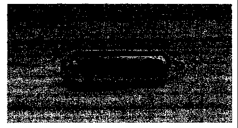
[0017] Figure 8 is a photograph of the inventive metal balloon catheter.
[0018] Figure 9 is a photograph of the inventive metal balloon catheter under
x-ray
imaging.
[0019] Figure 10A is a perspective view of the inventive metal balloon in its
inflated
state.
[0020] Figure l OB is a perspective view of the inventive metal balloon in its
deflated
state in accordance with one embodiment of the invention.
[0021] Figure l OC is an end view of the inventive metal balloon in its
deflated state.
[0022] Figure l OD is an end view of the inventive metal balloon in its
deflated state being
folded in accordance with one embodiment of the invention.
Detailed Description of the Preferred Embodiments
[0023] With particular reference to Figures 1-2, the inventive metal balloon
catheter 10
consists generally of a primary tubular catheter body member 12 and a balloon
14 situated at
a distal end of the metal balloon catheter 10. A proximal end of the metal
balloon catheter 10
(not shown) is provided with conventional fittings to couple with conventional
balloon
catheter control accessories. The body member 12 and the balloon 14 may both
be fabricated
of biocompatible metal and/or metals, which may be selected from the group
consisting of
titanium, vanadium, aluminum, nickel, tantalum, zirconium, chromium, silver,
gold, silicon,
magnesium, niobium, scandium, platinum, cobalt, palladium, manganese,
molybdenum and
alloys thereof, such as zirconium-titanium-tantalum alloys, nitinol, and
stainless steel.
Alternatively, the body member 12 may be fabricated of a biocornpatible
polymer and only
the balloon 14 is fabricated of a biocompatible metal, and affixed to the body
member 12
using a suitable biocompatible adhesive.
[0024] With each of the embodiments of the present invention described herein,
the metal
balloon 14 may consist of a single layer of a single metal, multiple layers of
a single layer or
a multiple layers of multiple metals. With a laminated structure, the metal
balloon 14 may
-4-
CA 02455417 2004-O1-30
WO 03/011363 PCT/US02/24800
include one or more radiopaque metals to enhance visualization of the metal
balloon 14 under
x-ray.
[0025] The balloon 14 is coaxially positioned about the body member 12 and
defines an
inflation lumen 16 between an inner wall of the balloon 14 and the body member
12. As with
conventional balloon catheters, the body member 12 is a tubular member and
includes an
inflation lumen 20 that communicates between the proximal end of the body
member 12 and
at least one inflation port 22 in fluid flow communication with the inflation
lumen of the
balloon 14. The inflation lumen 20 may also function as a guidewire lumen, or
a discrete
guidewire lumen 18 may be provided in the body member 12.
[0026] Conventional balloon catheters typically require a large number of
inflation ports
22 in order to meet governmental regulatory requirements for inflation and
deflation times.
However, it has been found with the present invention, that by fabricating the
balloon 14 of a
biocompatible metal having a wall thickness between 0.1 ~, and 25~. and
inflated outer
diameters between O.lmm and 40mm, that the regulatory requirements for
inflation and
deflation times may be met with a single inflation port 22.
[0027] By fabricating the balloon 14 of a biocornpatible metal, wall
thicknesses between
3~, and 12~, may be achieved, with the resulting metal balloon 14 exhibiting
zero compliance
with extremely high tensile strength. An additional advantage resulting from
the inventive
metal balloon 14 is that certain metals, such as nitinol, exhibit lubricious
surface properties
which eliminates the need for surface lubricants found with conventional
polymeric balloons.
Furthermore, in the embodiment where the inventive metal balloon is made from
a
superelastic material such as nitinol, the metal balloon may be fabricated
such that the low
profile configuration is associated with lowest strain state of the balloon
such that after
inflation the balloon reassumes the low profile configuration under its own
superelastic
properties. In the embodiment where the inventive metal balloon is made from a
shape
memory material such as nitinol, the metal balloon may be fabricated such that
the low
profile configuration is associated with lowest strain high temperature state
of the balloon
such that after inflation the balloon reassumes the low profile configuration
upon the
application of heat.
[0028] Turning to Figure 3 there is illustrated a drug delivery embodiment 30
of the
inventive metal balloon catheter. The inventive drug delivery metal balloon
catheter 30
consists generally tubular catheter body member 32 defining an inflation lumen
33 and
communicating with at least one inflation port 34, a first metal balloon 36
and a second metal
balloon 38 in coaxial, spaced-apart concentric relationship with one and
other, and an annular
-5-
CA 02455417 2004-O1-30
WO 03/011363 PCT/US02/24800
lumen 42 intermediate the first metal balloon 36 and the second metal balloon
38, which is in
fluid flow communication with an introductory lumen 46. The second metal
balloon 38 has a
plurality of pores 40 passing therethrough that are in fluid flow
communication with the
annular lumen 42. The first metal balloon 36 has a solid wall thickness. A
bioactive agent,
such as a pharmaceutical drug, is introduced, into the introductory lumen 46
and passes into
the annular lumen 42. The number and size of the plurality of pores 40 are
such that the
bioactive agent and its tamer will not pass through the pores 40 except under
the influence of
a positive pressure. A fluid, such as a saline solution, is introduced into
inflation 44 through
inflation lumen 33, and exerts a positive pressure on first balloon 36 which
communicates
that positive pressure to any bioactive agent present in annular lumen 42 and
second metal
balloon 38, and causes dilation of the first metal balloon 36 and the second
metal balloon 38
and forces the bioactive agent in annular lumen 42 to pass through the
plurality of pores 40 in
the second metal balloon 38.
[0029] A perfusion metal balloon catheter 50 is illustrated in Figure 4. 'The
inventive
perfusion metal balloon catheter 50 consists generally of a catheter body
member 54 and a
metal balloon 52 having a plurality of perfusion ports 56 passing through the
metal balloon.
As with conventional perfusion catheters, body fluids, such as blood, flow
into and through
the perfusion ports 56 and are perfused with a fluid introduced through the
catheter body
member 54.
[0030] Turning to Figures 5 and 6 there is illustrated an embodiment of the
inventive
metal balloon catheter 60 in which the surface topography of the metal balloon
62 is
configured to include a plurality of longitudinal beams or projections 64 that
project above
the surface of the metal balloon 62. By providing the projections 64, the
mechanical
properties of the metal film comprising the metal balloon 62 are altered to
create relatively ,
stronger regions along the longitudinal axis of the projections 64 and
relatively weaker
regions intermediate adjacent pairs of projections 64. In this configuration,
the relatively
weaker regions create fold lines for the metal balloon 62 during inflation and
deflation of the
metal balloon 62. Alternatively, the surface topography of the metal balloon
may be
configured in such as manner as to provide the projections 64 in a pattern
that corresponds to
the geometric pattern of an implantable device, such as a stmt, such that the
implantable
device is capable of nesting on the metal balloon 62 between the projections
64 during
endoluminal delivery.
[0031] Finally, with reference to Figure 7, there is illustrated an embodiment
70 of the
inventive metal balloon catheter in which the metal balloon 72 is coated with
an ultra thin
-6-
CA 02455417 2004-O1-30
WO 03/011363 PCT/US02/24800
coating of a biocompatible elastomer 74. Elastomer 74 adds a compliant
component to the
metal balloon 72 and serves to encapsulate the metal balloon and protect
against fragmenting
in the event of metal fatigue and/or cracking of the metal balloon 72.
[0032] In accordance with the method of the present invention, vacuum
deposition
methods as are known in the microelectronics and nano-fabrication arts are
preferably
employed. It is preferable to employ sputtering or ion beam-assisted
evaporative deposition
to deposit at least one metal film of a biocompatible metal onto a sacrificial
cylindrical
substrate. The sacrificial cylindrical substrate has a geometry corresponding
to the geometry
desired for the inventive metal balloon, and at least one of a plurality of
metal film layers are
deposited onto the sacrificial cylindrical substrate. After depositing a film
having a desired
thickness between 0.1 Nxn and 25 Nrn, the substrate and the deposited film are
removed from
the deposition chamber and the sacrificial substrate is removed by means
suitable for the
selected substrate. For example, a copper substrate may be employed, then
sacrificially
removed by chemical etching. Any patterning of nesting regions for a stmt
and/or
projections for creating fold lines for the balloon may be imparted either by
depositing metal
species through a mask or by etching regions of a deposited film. The entire
metal balloon
or selected regions of the metal balloon may be subject to post-deposition
annealing to alter
the crystalline structure of the metal film and effect changes in the material
properties of the
metal film, such as altering the transition temperature of the annealed
regions as well as to
create advantageous zero stress-strain configurations such as low profile
folds.
[0033] Figures 8 and 9 illustrate the inventive metal balloon catheter
fabricated by sputter
depositing nickel-titanium alloy onto a copper mandrel, etching the copper
mandrel to release
the deposited metal balloon, and adhering the metal balloon onto a polymeric
catheter body
using a cyanoacrylate biocompatible adhesive to attach proximal and distal
portions of the
metal balloon.
[0034] Figures 10A-1 OD depict the inventive metal balloon 110 in its inflated
state
(Figure 10A) having proximal 112 and distal 114 taper sections and an
intermediate enlarged
tubular section 118. In accordance with one embodiment of the invention, the
metal balloon
110 may be imparted with an deflated geometry as depicted in Figure l OB in
which the
intermediate section 118 and the proximal 112 and distal 114 taper sections
deflate to form a
configuration with a plurality of leaflets 120 that project radially outwardly
from the
longitudinal axis of the metal balloon 110. Figure lOC is an end view of
Figure 10B. Figure
l OD depicts folding of the leaflets 120 in order to accommodate endoluminal
delivery or
removal of the metal balloon 110.
_7_
CA 02455417 2004-O1-30
WO 03/011363 PCT/US02/24800
[0035] The deflated geometry depicted in Figure lOB may be imparted by a wide
variety
of means, including, without limitation, shape memory or superelastic
properties of the metal
material, fold or score lines along the metal balloon 110 defining fold
regions for the leaflets
120, or thickened regions of the metal balloon 110 intermediate the leaflets
120 that offer
greater resistance to folding upon deflation of the metal balloon 110.
[0036] In accordance with the preferred embodiment of fabricating the
inventive
microporous metallic implantable device in which the device is fabricated from
vacuum
deposited nitinol tube, a cylindrical deoxygenated copper substrate is shaped
into a
geometrical configuration corresponding to an inflated angioplasty balloon
having proximal
and distal tapers. The substrate is mechanically and/or electropolished to
provide a
substantially uniform surface topography for accommodating metal deposition
thereupon. A
cylindrical hollow cathode magnetron sputtering deposition device was
employed, in which
the cathode was on the outside and the substrate was positioned along the
longitudinal axis of
the cathode. A cylindrical target consisting either of a nickel-titanium alloy
having an atomic
ratio of nickel to titanium of about 50-50% and which can be adjusted by spot
welding nickel
or titanium wires to the target, or a nickel cylinder having a plurality of
titanium strips spot
welded to the inner surface of the nickel cylinder, or a titanium cylinder
having a plurality of
nickel strips spot welded to the inner surface of the titanium cylinder is
provided. It is known
in the sputter deposition arts to cool a target within the deposition chamber
by maintaining a
thermal contact between the target and a cooling jacket within the cathode. In
accordance
with the present invention, it has been found useful to reduce the thermal
cooling by
thermally insulating the target from the cooling jacket within the cathode
while still providing
electrical contact to it. By insulating the target from the cooling jacket,
the target is allowed
to become hot within the reaction chamber. Two methods of thermally isolating
the
cylindrical target from the cooling jacket of the cathode were employed.
First, a plurality of
wires having a diameter of 0.0381mm were spot welded around the outer
circumference of
the target to provide an equivalent spacing between the target and the cathode
cooling jacket.
Second, a tubular ceramic insulating sleeve was interposed between the outer
circumference
of the target and the cathode cooling jacket. Further, because the Ni-Ti
sputtering yields can
be dependant on target temperature, methods which allow the target to become
uniformly hot
are preferred.
[0037] 'The deposition chamber was evacuated to a pressure less than or about
2-5 x 10''
Torr and pre-cleaning of the substrate is conducted under vacuum. During the
deposition,
substrate temperature is preferably maintained within the range of 300 and 700
degrees
_g_
CA 02455417 2004-O1-30
WO 03/011363 PCT/US02/24800
Centigrade. It is preferable to apply a negative bias voltage between 0 and -
1000 volts to the
substrate, and preferably between -50 and -150 volts, which is sufficient to
cause energetic
species arriving at the surface of the substrate. During deposition, the gas
pressure is
maintained between 0.1 and 40 mTorr but preferably between 1 and 20 mTorr.
Sputtering
preferably occurs in the presence of an Argon atmosphere. The argon gas must
be of high
purity and special pumps may be employed to reduce oxygen partial pressure.
Deposition
times will vary depending upon the desired thickness of the deposited tubular
film. After
deposition, the plurality of microperforations are formed in the tube by
removing regions of
the deposited film by etching, such as chemical etching, ablation, such as by
excimer laser or
by electric discharge machining (EDM), or the like. After the plurality of
microperforations
are formed, the formed microporous film is removed from the copper substrate
by exposing
the substrate and film to a nitric acid bath for a period of time sufficient
to remove dissolve
the copper substrate.
[0038] While the present invention has been described with reference to its
preferred
embodiments, those of ordinary skill in the art will understand and appreciate
that variations
in materials, dimensions, geometries, and fabrication methods may be or become
known in
the art, yet still remain within the scope of the present invention which is
limited only by the
claims appended hereto.
_g_