Language selection

Search

Patent 2455611 Summary

Third-party information liability

Some of the information on this Web page has been provided by external sources. The Government of Canada is not responsible for the accuracy, reliability or currency of the information supplied by external sources. Users wishing to rely upon this information should consult directly with the source of the information. Content provided by external sources is not subject to official languages, privacy and accessibility requirements.

Claims and Abstract availability

Any discrepancies in the text and image of the Claims and Abstract are due to differing posting times. Text of the Claims and Abstract are posted:

  • At the time the application is open to public inspection;
  • At the time of issue of the patent (grant).
(12) Patent Application: (11) CA 2455611
(54) English Title: FRICTION STIR TOOL FOR FRICTION WELDING
(54) French Title: OUTIL DE MELANGE PAR FRICTION DESTINE AU SOUDAGE PAR FRICTION
Status: Deemed Abandoned and Beyond the Period of Reinstatement - Pending Response to Notice of Disregarded Communication
Bibliographic Data
(51) International Patent Classification (IPC):
  • B23K 20/12 (2006.01)
(72) Inventors :
  • RAETHER, KLAUS (Germany)
  • SILVANUS, JUERGEN (Germany)
  • ZIMMERMANN, WERNER (Germany)
(73) Owners :
  • EADS DEUTSCHLAND GMBH
(71) Applicants :
  • EADS DEUTSCHLAND GMBH (Germany)
(74) Agent: KIRBY EADES GALE BAKER
(74) Associate agent:
(45) Issued:
(86) PCT Filing Date: 2002-08-02
(87) Open to Public Inspection: 2003-02-27
Availability of licence: N/A
Dedicated to the Public: N/A
(25) Language of filing: English

Patent Cooperation Treaty (PCT): Yes
(86) PCT Filing Number: PCT/DE2002/002858
(87) International Publication Number: WO 2003015975
(85) National Entry: 2004-01-26

(30) Application Priority Data:
Application No. Country/Territory Date
101 39 687.2 (Germany) 2001-08-11

Abstracts

English Abstract


The invention relates to a friction stir tool for friction welding, which may
be controlled with adequate accuracy according to the temperature in the
welding zone. According to the invention, the above is achieved, whereby the
temperature values for the welding zone (6) are determined with a temperature
sensor (7), arranged with the measuring position thereof in the pin (4) of the
friction stir tool (1).


French Abstract

L'invention vise à mettre en oeuvre un outil de mélange par friction destiné au soudage par friction, pouvant être commandé avec une précision de mesure suffisante en fonction de la température de la zone de soudage. A cet effet, les valeurs de température de la zone de soudage (6) sont relevées au moyen d'un capteur de température (7) dont la zone de mesure est disposée dans la broche (4) de l'outil de mélange par friction (1).

Claims

Note: Claims are shown in the official language in which they were submitted.

-4-
Claims
1. A friction stir welding tool for friction welding having a control that
takes into consideration
the measured temperature values of the weld zone, wherein the temperature
values of the
weld zone (6) are determined by a temperature sensor (7) that is arranged with
its
measuring point in the pin (4) of the friction stir welding tool (1).
2. Friction welding tool of patent claim 1, wherein the temperature sensor (7)
is integrated in
an autarchic telemetric measuring system (10) located on the tool, which
continuously
transmits the measured temperature values to a control unit of the tool
located outside of the
friction stir welding tool.
3. Friction stir welding tool of patent claim 1 or 2, wherein the temperature
sensor (7) is a
thermal element.
4. Friction stir welding tool of patent claim 1 or 2, wherein the temperature
sensor (7) is a
pyrometer having a sapphire rod ending in the pin (4) or an optical fiber
ending in the pin.

Description

Note: Descriptions are shown in the official language in which they were submitted.


"r . CA 02455611 2004-O1-26
. .
P610588/W0/1 - 1 -
Friction Stir Welding Tool for Friction Welding
The invention concerns a friction stir welding tool for friction welding in
accordance with the
preamble of patent claim 1.
The friction welding process is described; for example, in WO 95!26254 A1. To
produce a good
welded connection, this publication discloses guiding a friction stir welding
tool with vertical
pressure along the connecting point of the workpiece to be welded. It is
particularly
advantageous to provide the friction stir welding tool with a concave shoulder
and a pin
configured in a screw shape.
Also of great importance in friction stir welding is the adjustment of a
temperature that is suitable
for the welding procedure in the stirred material of the weld zone. This
temperature is
influenced, among other things, by the parameters of the welding process, such
as the rate of
feed, the number of revolutions, and the contact pressure of the friction stir
welding tool. Also
known is the process of influencing these by means of cooling devices if
necessary.
It is known in friction stir welding to measure the temperature in the stirred
material of the weld
zone in order to control the welding procedure in accordance to the measured
temperature
values.
One known measuring process consists in recording the temperature of the
welded plates in the
vicinity of the weld zone. Since the plates cool off considerably a short
distance from the weld
zone, the temperature of the stirred material of the weld zone cannot be
determined with
sufficient accuracy with this measuring process.
Another known measuring method for determining the weld zone temperature
consists in using
a pyrometer. As optical radiation measurement, this measuring method is
impaired in its
measurement accuracy by the structured surface of the welding location.
Such pyrometers are also used for the online monitoring of the quality of roll
welding joints or
mash seam welding joints as is described, for example, in EP 1 075 892 A2.

CA 02455611 2004-O1-26
P610588lWO11 - 2 -
The object of the invention is to create a friction stir welding tool for
friction welding that can be
controlled with sufficient measuring accuracy based upon the temperature in
the weld zone.
This object is attained in accordance with the invention with the
characterizing features of patent
claim 1. Further developments of the invention are disclosed in the dependent
claims.
In the temperature measuring process of the invention, the temperature of the
weld zone is
recorded by means of a temperature measuring device whose measuring element is
arranged
in the pin of the friction stir welding tool.
The measurement location is separated from the weld zone only by the thermally
conductive
wall of the pin, and a good correspondence can therefore be achieved between
the measured
and the actual temperature values of the weld zone.
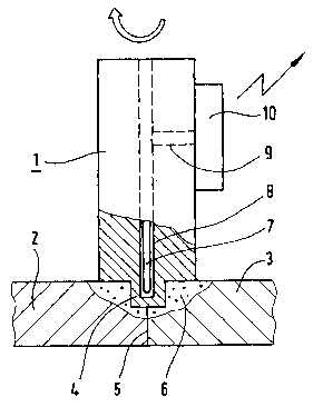
One exemplary embodiment of the invention will be explained in more detail
below with
reference to the drawing. The drawing shows a section view through a friction
stir welding tool
1.
Two plates 2 and 3 that come into blunt contact with each other are welded
together, for
example, with the friction stir welding tool 1. The pin 4 of the friction stir
welding tool is frictioned
into the two plates 2 and 3 by means of a pressure, rotation, and forward
motion of the stirring
tool in a known manner, along the contact joint 5. After cooling, the stirred
material forms the
weld seam in the weld zone 6 that is produced in this manner.
The stirring tool 1 is provided with a blind bore 8, which ends in a pin 4,
and wherein a
temperature sensor 7 can be accommodated. The electric connections for the
sensor are
guided via a radial bore 9 to a telemetric measuring system 10, which is
arranged on the
surface of the stirring tool underneath its clamping area.
The temperature sensor 7 can be configured, for example, as a standard thermal
element. An
electronic evaluation system for the thermal element and a transmitter
equipped with a suitable
receiver for the telemetric transmission of the measured temperature values to
the control unit

' CA 02455611 2004-O1-26
P610588/W0/1 - 3 -
of the stirring tool are accommodated in the telemetric measuring system 10.
The electric
current to the electronic evaluation system and the transmitter is supplied by
means of a battery,
which is accommodated in the measuring system 10.
The telemetric transmission can be implemented by means of different processes
known to an
expert in the field, for example, within the VHF range by means of microwaves
or within the
infrared range.
An alternative for the temperature sensor 7 consists in introducing a sapphire
rod or an optical
fiber instead of the thermal element into the blind bore 8, with which the
thermal radiation
existing in the pin is optically transmitted to a pyrometer, which is
accommodated in the
measuring system 10, and which feeds the temperature measured values following
electronic
processing to the VHF transmitter.

Representative Drawing
A single figure which represents the drawing illustrating the invention.
Administrative Status

2024-08-01:As part of the Next Generation Patents (NGP) transition, the Canadian Patents Database (CPD) now contains a more detailed Event History, which replicates the Event Log of our new back-office solution.

Please note that "Inactive:" events refers to events no longer in use in our new back-office solution.

For a clearer understanding of the status of the application/patent presented on this page, the site Disclaimer , as well as the definitions for Patent , Event History , Maintenance Fee  and Payment History  should be consulted.

Event History

Description Date
Application Not Reinstated by Deadline 2006-08-02
Time Limit for Reversal Expired 2006-08-02
Deemed Abandoned - Failure to Respond to Maintenance Fee Notice 2005-08-02
Letter Sent 2005-05-20
Inactive: Single transfer 2005-04-26
Inactive: Courtesy letter - Evidence 2004-03-23
Inactive: Cover page published 2004-03-22
Inactive: Notice - National entry - No RFE 2004-03-17
Application Received - PCT 2004-03-01
National Entry Requirements Determined Compliant 2004-01-26
Application Published (Open to Public Inspection) 2003-02-27

Abandonment History

Abandonment Date Reason Reinstatement Date
2005-08-02

Maintenance Fee

The last payment was received on 2004-07-22

Note : If the full payment has not been received on or before the date indicated, a further fee may be required which may be one of the following

  • the reinstatement fee;
  • the late payment fee; or
  • additional fee to reverse deemed expiry.

Please refer to the CIPO Patent Fees web page to see all current fee amounts.

Fee History

Fee Type Anniversary Year Due Date Paid Date
Registration of a document 2004-01-26
Basic national fee - standard 2004-01-26
MF (application, 2nd anniv.) - standard 02 2004-08-02 2004-07-22
Owners on Record

Note: Records showing the ownership history in alphabetical order.

Current Owners on Record
EADS DEUTSCHLAND GMBH
Past Owners on Record
JUERGEN SILVANUS
KLAUS RAETHER
WERNER ZIMMERMANN
Past Owners that do not appear in the "Owners on Record" listing will appear in other documentation within the application.
Documents

To view selected files, please enter reCAPTCHA code :


To view images, click a link in the Document Description column. To download the documents, select one or more checkboxes in the first column and then click the "Download Selected in PDF format (Zip Archive)" or the "Download Selected as Single PDF" button.

List of published and non-published patent-specific documents on the CPD .

If you have any difficulty accessing content, you can call the Client Service Centre at 1-866-997-1936 or send them an e-mail at CIPO Client Service Centre.


Document
Description 
Date
(yyyy-mm-dd) 
Number of pages   Size of Image (KB) 
Abstract 2004-01-26 1 13
Claims 2004-01-26 1 23
Drawings 2004-01-26 1 10
Description 2004-01-26 3 114
Representative drawing 2004-01-26 1 9
Cover Page 2004-03-22 1 36
Reminder of maintenance fee due 2004-04-05 1 109
Notice of National Entry 2004-03-17 1 192
Request for evidence or missing transfer 2005-01-27 1 101
Courtesy - Certificate of registration (related document(s)) 2005-05-20 1 104
Courtesy - Abandonment Letter (Maintenance Fee) 2005-09-27 1 173
PCT 2004-01-26 4 131
Correspondence 2004-03-17 1 26