Note: Descriptions are shown in the official language in which they were submitted.
CA 02455643 2009-03-13
Utility Lighter
Field of the Invention
The present invention relates to a utility lighter.
Background of the Present Invention
There are numerous utility lighters on the market.
Utility lighters all have a rod-like top end portion and a
main body. The rod-like top end portion has a jetting nozzle
for jetting out a fuel to form a flame protruding therefrom.
The main body has the following elements:
1) a fuel tank,
2) a valve mechanism for opening and closing a path,
through which the fuel is supplied from the fuel
tank to the jetting nozzle,
3) a spark generating device which lights the fuel and
the spark is generated by a conventional piezo-
electric unit or a conventional flint wheel
assembly, and
4) an operation member which drives the valve mechanism
and the spark generating device in order to carry
out the lighting operation.
Such devices are well known to those skilled in the art.
Internationally, there is a drive for such lighters to
become child resistant. It has come to the applicant's
attention that Saito et al. in U.S. Patent no. 5,697,775 and
Fremund in U.S. Patent no. 5,076,783, disclose similar child
safety devices for lighters. In particular, both patents claim
and disclose a safety device having the following generic
elements:
a) a locking member, which interferes with the
CA 02455643 2009-03-13
- 2 -
operation member and thereby locks the lighting operation
of the operation member, the locking member being capable
of moving in a direction, that intersects with the
direction along which the operation member moves, and
b) an urging member which urges the locking member to a
locking direction,
c) the safety device being provided with an unlocking
member, which is capable of being operated in order to
move the locking member in a direction, that acts against
the urging force of the urging member, the unlocking
member being projected to the exterior of the main body
on the side opposite to the operation member,
wherein when the locking member is released from a
position preventing the lighting operation by operating
the unlocking member, the lighting operation is carried
out by operating the operating section of the operation
member, and the locking member automatically returns to
the state of the locking as the operation member returns
to its original position.
The particular locking members and the operating members
of Saito et al. and Fremund, however, are not always stable
and do not provide the desired child resistant
characteristics.
For example, Saito et al. disclose a bar-like shaft,
which is inserted transversely through the main body, and an
engagement section, which is located at one end of said bar-
like shaft. The engagement section is designed to be inserted
into an engagement groove of the operation member to interfere
with the movement of the operation member. It is possible that
the engagement section can become permanently positioned in
CA 02455643 2009-03-13
- 3 -
the engagement groove to render the utility lighter useless or
the engagement section can become dislodged so the utility
lighter has no child resistance at all.
In contrast, Fremund discloses "when the lighter is not
being used, [a] spring ... has [a] locking slide ... pushed to
the right overlying [a] spring-loaded latch ... and [a] lower
end ... of [a] locking rod ... rests on the right hand end ...
of the locking slide ... and it cannot be depressed and the
lighter cannot be operated. When it is desired to use the
lighter, the user pushes on [a] projection ... on the locking
slide ... and pushes the locking slide to the left to free the
latch ... and actuating locking rod .... The latch ... hits a
notch ... on the inside of the outer wall of the lighter
assembly and is in such a position that the slide ... cannot
move to the right. Now the user can operate the activating
lever ... and to light the lighter. When the lever ... is
compressed, the spring latch ... is pushed down and the
locking slide ..., whose end overlies slightly the spring-
loaded latch ..., is pushed to the right to rest against the
locking rod .... When the lighter actuating lever ... returns,
it pulls the locking rod ... upwardly above the locking
slide's right hand end .... This allows the locking slide
to return, by the force of the spring ..., to its rightmost
position and to lock the locking rod ... again in the
inoperative position." As disclosed, Fremund's child resistant
system has stability problems because the locking slide is a
single rod that can easily break.
Thus, there remains a need for a utility lighter which
resists unwanted actuation, minimizes wiring, ignites
efficiently and reliably, and minimizes the impact of
..~
CA 02455643 2009-03-13
- 4 -
manufacturing variances. The present invention solves these
problems.
Summary of the Invention
The present invention is directed to a utility lighter
having a housing, a nozzle, a lighter fluid reservoir, a
conduit, an igniter assembly, a valve actuator, and a locking
device. The housing has a top side, a bottom side, sides, a
distal end, and a proximal end. The nozzle extends away from
the distal end and has a nozzle tip. The lighter fluid
reservoir is in the distal end. The conduit delivers the
lighter fluid from the reservoir through the conduit to the
nozzle tip. The igniter assembly generates a spark at a spark
gap near the nozzle tip to ignite the lighter fluid, and has a
conventional piezoelectric component. The valve actuator is
associated with the lighter fluid for selectively releasing
the lighter fluid from the reservoir, and the igniter
assembly. A compressor is connected to the valve actuator and
when the valve actuator moves toward the nozzle tip, the valve
actuator releases the lighter fuel and then sequentially
activates the igniter assembly by having the compressor
compress the piezoelectric component. The locking device
diminishes the undesirable movement of the valve actuator.
Brief Description of the Drawings
Figure 1 illustrates an exploded view of the present
invention with the housing 12.
Figure 2a illustrates Figure 1 without the housing 12 and
the operation member 27a.
Figure 2b illustrates Figure 2b without the
operation member 27b.
CA 02455643 2009-03-13
- 5 -
Figure 3 illustrates a valve mechanism in the open
position.
Figure 4 illustrates the valve mechanism in the closed
position.
Figure 5a illustrates the spark generating device 24 in
its relaxed state.
Figure 5b illustrates the spark generating device 24 in
its potential energy state with a spark 25 at the spark gap.
Figure 6 is a side view of the safety unit and the
operation member, without the interior housing.
Figure 7 is the bottom side of the operation member.
Figure 8 is the bottom side of Figure 2b without the
tank.
Figure 9 is side operational view of the safety unit and
the operation member in their relaxed states.
Figure 10 illustrates a side operation view of the safety
unit in its potential energy state and the operational member
in its relaxed state.
Figure 11 is a top view of an adjustment knob.
CA 02455643 2004-01-23
WO 03/012340 PCT/US02/23629
--6 --
Detailed Description of the Invention
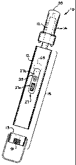
The present invention is a utility lighter 10, as
illustrated in Figure 1. In Figure 1, the utility
lighter 10 illustrates an exterior housing 12 and an end
cap 13 which define a main body 15, and a nozzle 14. The
main body 15 contains many of the components that allow
the utility lighter 10 to generate a flame at the
terminal end 38 of the nozzle 14. These main components
are
1) a fuel tank 20 as shown in Figures 2a and
b,
2) a valve mechanism 22 for opening (as shown
in Figure 3) and closing (see Figure 4) a
conduit 23, through which the fuel is
supplied from the fuel tank 20 to the
terminal end 38,
3) a spark generating device 24 which lights
the fuel from the conduit 23 at the
terminal end 38 and as shown in Figure 5a
a spark 25 is generated when a resilient
extension member 26 is compressed, as
shown in relation between Figure 5a and
5b, wherein the device 24 is a
conventional piezo-electric unit assembly,
4) an operation member 27 which drives the
valve mechanism 22 and the spark
generating device 24 in order to carry out
the lighting operation, and
5) an internal housing 28 that holds all the
main components in the proper position.
CA 02455643 2004-01-23
WO 03/012340 PCT/US02/23629
--7--
The operation member 27 is divided into two
components, a finger member 27a and an internal member
27b. The finger member 27a is designed to allow a user's
fingers (or thumb) to easily slide the operation member
27 toward the terminal end 38. The finger member 27a
protrudes from an operation aperture 39 of the housing
12.
The internal member 27b has a plurality of apertures
40. The apertures 40 receive corresponding prongs 41
which extend from the finger member 27a. That way, the
finger member 27a is securely attached to the internal
member 27b. The internal member 27b remains within the
housing 12 but a portion of the internal member 27b can
be exposed through the operation aperture 39.
On the opposite side of the internal member 27b that
has the finger member 27a (as shown in Figure 6), are a
valve latch 50, a driving head 51, and at least one
interference member 52, as shown in Figure 7. The valve
latch 50 is designed to be positioned to drive a latch 53
of the valve mechanism 22 toward the terminal end 38 when
the operation member 27 is moved forward. By moving the
latch 53 forward, as shown in Figure 3, the fuel from the
fuel tank 20 is released into the conduit 23.
The latch 53 is attached to a compression conduit 54
that when the latch 53 not moved forward, as shown in
Figure 4, the compression conduit 54 does not allow the
fuel to be released from the tank 20 into the conduit 23.
And when the latch 53 is moved forward as shown in Figure
3 the compression conduit 54 allows the fuel to be
released from the tank 20 into the conduit. The latch
CA 02455643 2004-01-24 PffAS02./23629
ram. O.~~P 2,003
= --8 --
53, however, is not moved forward until the operation
member 27 is moved forward.
The operation member 27 cannot move forward until
the safety unit 60 is moved into the housing 12 a
predetermined distance. The safety unit 60 is divided
into an external cap 61 and a resilient interference
protrusion unit 62. The external cap 61 protrudes from
the housing 12 through a safety aperture 63, which is on
the opposite side of the operation aperture 39 and when a
~ 10 user examines just the housing 12 through the operation
aperture, the user will see a portion (the portion facing
away from the terminal end 38) of the safety aperture 39.
The protrusion unit 62 is larger (a shoulder) than
` the safety aperture 39 (that way it will not be displaced
from the lighter 10), and has at least one resilient
member 63 that forces the unit toward the safety aperture
39, and at least one "L" shaped protrusion 64, wherein
the L faces away from the terminal end 38. The L shaped
protrusion 64 is divided into a vertical extension 64a
and a horizontal extension 64b.
The unit 62 is positioned to contact the internal
housing 28, opposite the operation member 27, within a
safety receiver 65, as shown in Figure 8. The safety
receiver 65 has at least one protrusion aperture 66, at
least one resilient protrusion 67 which receives the
resilient member 63, and a boundary wall 68 that contains
the safety unit 60 within the lighter 10. That way, the
unit 62 in the relaxed mode is pushed toward the safety
aperture 39.
When the unit 62 is in the relaxed mode, the
protrusion 64 member, is positioned within a corresponding
protrusion aperture 66. In particular, the horizontal
AMENDED
SWAT
CA 02455643 2004-01-23
WO 03/012340 PCT/US02/23629
--9 --
extension 64b protrudes just beyond the protrusion
aperture 66 as shown in Figure 9. In that position,
horizontal extension 64b interferes with the movement of
the operation member 27. In particular, the operation
member 27 has a corresponding "L" shape unit 52 having a
vertical member 52a that protrudes toward the interior
housing 28 and a horizontal member 52b. The horizontal
member 52b and horizontal extension 64b are designed to
contact each other when the unit 62 is in the relaxed
state, as shown in Figure 9. By contacting each other,
the operation member 27 is unable to move forward and
thereby the user is unable to operate the lighter 10.
When the user depresses the unit 62 into the housing
12, the protrusion 64 is moved further into the housing
12. That means the horizontal extension 64b is
positioned above the upper surface 70 of the horizontal
member 52b, as shown in Figure 10. Once the unit 62 is
in this potential energy position, the user can now
freely move the operation member 27 forward toward the
terminal end 38 because the horizontal extension 64b and
the horizontal member 52b will not contact each other.
Once the operation member 27 is moved forward toward
the terminal end 38, the operation member 27 drives the
valve mechanism 22 and the spark generating device 24 in
order to carry out the lighting operation. How the
operation member 27 drives the valve mechanism 22 is set
forth above.
The operation member 27 drives the spark generating
device 24 through the driving head 51. The driving head
51 is moved forward and contacts the spark generating
device 24. Device 24 is a conventional piezoelectric
lighter unit that amplifies the contact force of the
CA 02455643 2004-01-24 02f ~ ~ ~ 29,
21 SEP 200 1
2 3S-F2C:4
--10--
driving head 24 through the resilient extension member 26
to generate the standard electrical impulse from the
piezoelectric unit for generating the spark near the
terminal end 38.
The electrical impulse is transmitted through a wire
80 and the spark 25 is generated when the electrical
signal has to jump (spark gap) to corresponding
electrical contact 80b. When the spark 25 is generated,
the fuel from the tank 20 was released into the conduit
23.that directs the fuel to a metallic conduit 95 that
simultaneously transmits the fuel and is the receiving
contact 80b of the spark 25. That way, the fuel is lit,
and the lighter 10 has generated its desired flame with a
quality safety system.
Once the user wants to terminate the flame, the user
merely releases the operation member 27. The operation
member 27 through the resilient extension member 26 will
return the operation member to the relaxed state
illustrated in Figure 9. Also, the user can release the
safety unit 60, which will also return to the relaxed
state, illustrated in Figure 9, in response to the
resilient member 63.
In addition, the tank 20 has a conventional
refilling port and flame adjuster control unit 90. The
unit 90 protrudes from the tank 20 as illustrated in
Figures 2a and b, and through the end cap 13. To allow
the user to adjust the unit 90, the end cap 13 has an
adjustment knob 91. The knob 91, as shown in Figure 11,
has an aperture 92 that allows a user to refill the tank
20, through conventional methods.
ANIENDED Mgl
CA 02455643 2004-01-23
WO 03/012340 PCT/US02/23629
--11--
In addition, the housing 12 has a tank aperture, not
shown, that allows a user to see how much fuel is in the
tank 20.
Although variations in the embodiment of the present
invention may not each realize all the advantages of the
invention, certain features may become more important
than others in various applications of the device. The
invention, accordingly, should be understood to be
limited only by the scope of the appended claims.