Language selection

Search

Patent 2455744 Summary

Third-party information liability

Some of the information on this Web page has been provided by external sources. The Government of Canada is not responsible for the accuracy, reliability or currency of the information supplied by external sources. Users wishing to rely upon this information should consult directly with the source of the information. Content provided by external sources is not subject to official languages, privacy and accessibility requirements.

Claims and Abstract availability

Any discrepancies in the text and image of the Claims and Abstract are due to differing posting times. Text of the Claims and Abstract are posted:

  • At the time the application is open to public inspection;
  • At the time of issue of the patent (grant).
(12) Patent: (11) CA 2455744
(54) English Title: WIND ENERGY INSTALLATION
(54) French Title: INSTALLATION D'ENERGIE EOLIENNE
Status: Term Expired - Post Grant Beyond Limit
Bibliographic Data
(51) International Patent Classification (IPC):
  • F24F 5/00 (2006.01)
(72) Inventors :
  • WOBBEN, ALOYS (Germany)
(73) Owners :
  • ALOYS WOBBEN
(71) Applicants :
  • ALOYS WOBBEN (Germany)
(74) Agent: OYEN WIGGS GREEN & MUTALA LLP
(74) Associate agent:
(45) Issued: 2009-02-03
(86) PCT Filing Date: 2002-07-01
(87) Open to Public Inspection: 2003-02-20
Examination requested: 2004-01-28
Availability of licence: N/A
Dedicated to the Public: N/A
(25) Language of filing: English

Patent Cooperation Treaty (PCT): Yes
(86) PCT Filing Number: PCT/EP2002/007225
(87) International Publication Number: WO 2003014629
(85) National Entry: 2004-01-28

(30) Application Priority Data:
Application No. Country/Territory Date
101 39 556.6 (Germany) 2001-08-10

Abstracts

English Abstract


The present invention concerns a wind power installation, in
particular a wind power installation having an apparatus for the
dehumidification of a gaseous medium in a substantially closed space within
the wind power installation. In order to keep down the personnel and
logistical expenditure for attaining proper operability of the apparatus, to
simplify the structure and to permit very substantially maintenance-free
operation, the apparatus includes a first aereal element and a cooling
device for cooling the first element to a temperature below the ambient
temperature.


French Abstract

La présente invention concerne une installation d'énergie éolienne, notamment une installation d'énergie éolienne comprenant un dispositif conçu pour déshydrater un milieu gazeux dans un espace sensiblement clos, à l'intérieur de cette installation d'énergie éolienne. L'objectif de la présente invention est de minimiser les ressources en personnel et en logistique nécessaires pour maintenir le bon fonctionnement du dispositif, de simplifier la construction et de minimiser l'entretien. A cette fin, le dispositif comprend un premier élément plan (10) et un dispositif de refroidissement (12) conçu pour refroidir ledit premier élément à une température située en-dessous de la température ambiante.

Claims

Note: Claims are shown in the official language in which they were submitted.

6
CLAIMS
1. A wind power installation, comprising a pylon and a machine housing
arranged on top
of the pylon, a generator, a transformer, a rectifier coupled to the
transformer, and a device for
dehumidifying air inside the wind power installation, which is arranged in the
proximity of at
least one of the generator, the transformer, the rectifier and a region of a
base of the pylon of the
wind power installation,
wherein the device for dehumidifying the air inside the wind power
installation comprises
a first element (10) and a cooling device coupled to the first element for
cooling the first element
(10) to a temperature below a temperature in the proximity of at least one of
the generator, the
transformer, the rectifier and the region at the base of the pylon.
2. A wind power installation according to claim 1 characterised in that the
dehumidification device is characterised by the first element (10) and the
cooling device (12)
coupled thereto for cooling the first element (10) to a temperature below
ambient temperature,
wherein the air dehumidification device is arranged substantially within the
interior of the wind
power installation.
3. A wind power installation according to claim 1 or claim 2 characterised in
that a
second element (14) is connected to a wall (32) or is formed by the wall (32).
4. A wind power installation according to claim 3 characterised in that the
cooling device
(12) is arranged between the first element (10) and the second element (14).
5. A wind power installation according to any one of claims 1 to 4
characterised by the
cooling device which utilises the Peltier effect.
6. A wind power installation according to any one of claims 1 to 5
characterised in that at
least one of a catch unit and a duct for removal of a liquid extracted from a
gaseous medium is

7
provided.
7. A wind power installation according to claim 6 characterised in that the
liquid caught
with the first element (10) is drained by way of a duct (20).
8. A wind power installation according to claim 7 characterised in that the
duct is
arranged in the region, near the ground, in the base region of the pylon.
9. A wind power installation according to any one of claims 1 to 8
characterised in that
provided for catching the liquid extracted from a gaseous medium is a catch
space in which the
liquid is collected.
10. A wind power installation according to any one of claims 1 to 9
characterised in that
there are provided a first temperature sensor (16) for detecting the
temperature of the first
element (10) and a second temperature sensor (18) for detecting the ambient
temperature, that the
temperatures are detected and processed by a control device, and the control
device sets the
temperature of the first element by variations in the cooling power of the
cooling device (12).
11. A wind power installation according to claim 10 characterised in that the
control
device is controlled in such a way that the temperature of the first element
(10) is a
predeterminable amount below the ambient temperature or that the temperature
does not exceed a
predeterminable temperature.
12. A wind power installation comprising a pylon and a machine housing
arranged at the
top of the pylon for accommodating various machine assemblies of the wind
power installation,
characterised in that a dehumidifying device, according to any one of claims 1
to 11, is arranged
within one or both of the pylon and the machine housing; and arranged in the
pylon and/or the
machine housing is a device according to any one of claims 1 to 11.

8
13. A wind power installation according to claim 12 characterised in that the
device is
arranged approximately in the region of the base of the pylon of the wind
power installation.
14. A wind power installation according to any one of claims 1 to 13
characterised in that
a plurality of air dehumidification devices in accordance with any one of
claims 1 to 13 are
arranged in the wind power installation.
15. A wind power installation according to any one of claims 1 to 14
characterised in that
approximately one to ten litres of water per day are extracted from the air
with each air
dehumidification device and the total electrical power of the air
dehumidification device is
approximately in the range between 50 and 500 W.
16. A wind power installation according to any one of claims 1 to 15
characterised in that
approximately two to five litres of water per day are extracted from the air
with each air
dehumidification device and the total electrical power of the air
dehumidification device is
approximately in the range between 50 and 500 W.
17. A device for dehumidifying a gaseous medium in an interior of a wind power
installation, comprising
a first element (10) and a cooling device (12) coupled to the first element
for cooling the
first element to a temperature below an ambient temperature, and
a second element (14) for dispersing heat transferred from the first element
(10), wherein
the second element (14) is connected to a pylon wall of the wind power
installation or is formed
by the pylon wall of the wind power installation.

Description

Note: Descriptions are shown in the official language in which they were submitted.


CA 02455744 2008-08-27
Aloys WOBBEN
Argestrasse 19, 26607 Aurich
WIND ENERGY INSTALLATION
The present invention concerns a wind power installation, in
particular a wind power installation having an apparatus for dehumidifying
a gaseous medium in a substantially closed space within the wind power
installation.
Such an apparatus operating on a chemical basis has long been
known. In that known apparatus moisture is removed from the ambient air
chemically and the moisture is collected in a catch container. That known
apparatus however suffers from the disadvantage that the chemical has to
be replaced at certain time intervals in order to maintain proper operability
of the apparatus. In relation to a large number of apparatuses which are to
be centrally monitored and maintained, that requires additional expenditure
in terms of personnel and logistics.
Apparatuses of the kind set forth in the opening part of this
specification are also known, in which an enclosed space is cooled on the
basis of the operative principle of a refrigerator by way of a
compressor/evaporator unit by means of a coolant specifically provided for
that purpose, in order in that way to remove moisture from the air
contained in that space.
With those apparatuses however the structure is complicated and
expensive and in addition it is necessary for the cooling fluid to be
collected
separately upon disposal.
Therefore the object of the present invention is to develop a wind
power installation and in particular to design a wind power installation in
such a way that moisture problems within the wind power installation can
be eliminated in a simple manner.
That object is attained by a wind power installation having the
features of cla-im 1. Advantageous developments are set forth in the
appendant claims. In the wind power installation according to the invention
the object is attained by a first flat or aereal element and a cooling device

CA 02455744 2004-01-28
2
for cooling the element to a temperature below the ambient temperature
(room temperature). At that ambient temperature a part of the moisture
contained in the air condenses at the surface of the first element. That
moisture is removed from the ambient air in that way and can be drained
off.
In order'to permit maintenance-free long-term operation the cooling
device is preferably a Peltier element or a group of Peltier elements which
withdraw heat from the first element and thereby cool that element. The
heat which is withdrawn from the first element is discharged to the ambient
atmosphere again by way of a second element.
In order to achieve a particularly good effect the second element can
be connected to a wall delimiting the space to be dehumidified or can even
be formed by that wall.
The condensate water can be discharged into the open through a
duct and a wall opening. In that case the wall opening can preferably be
provided in the region of the ground in order to avoid traces of dripping
water on outside walls.
In order to prevent the condensate water from uncontrolledly
dripping down within the space in the event of a blockage of the duct for
draining off the condensate water, it is possible to provide a container
which catches those drips. Thus the container can be emptied in the
context of an inspection procedure or after signalling from a sensor suitably
arranged in the container. At the same time the closure of the duct can be
removed so that the condensate water is again automatically removed from
the space.
In a particularly preferred development of the invention there is
provided a first temperature sensor for detecting the temperature of the
first element and a second temperature sensor for detecting the ambient
temperature. The apparatus according to the invention can be controlled by
means of those sensors and a control device connected on the output side
thereof, in such a way that the first element is always at a predeterminable
temperature difference with respect to the ambient temperature. A
constant dehumidification output can be achieved in that way.

CA 02455744 2004-01-28
3
Advantageous embodiments are recited in the appendant claims.
Room air humidifiers are already known from DE-U-92 10 970.5, DE
44 23 851, German patent specification No 1 189 250, EP 0 758 730 A2
and US No 5 071 027. The use of such room air humidifiers within wind
power installations has hitherto not been proposed.
An embodiment of the invention is described in greater detail
hereinafter with reference to the drawings in which:
Figure 1 shows a perspective view of an apparatus according to the
invention,
Figure 2 shows a further view of the apparatus according to the
invention,
Figure 3 shows an arrangement of an apparatus according to the
invention in the pylon of a wind power installation, and
Figure 4 shows a perspective view of an apparatus according to the
invention.
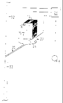
Referring to Figure 1 shown therein is a side view of an apparatus
according to the invention. Disposed between a first element 10 and a
second element 14 is a cooling device 12. The cooling device 12 is a Peltier
element operated with electrical power or a group of Peltier elements. It
causes transportation of heat from a lateral boundary surface to the other -
in this case the heat is transported from the first element 10 to the second
element 14.
If the cooling device 12 is acted upon by a suitable current which is
predetermined in respect of amount and direction, heat is withdrawn from
the first element 10 and transported to the second element 14 where it is
in turn discharged to the ambient atmosphere. The first element 10 and the
second element 14 are preferably in the form of cooling bodies, that is to
say flat or aereal aluminium elements with cooling ribs extending thereon
for increasing the effective surface area.
Due to the extraction of heat the first element 10 cools down to
below the ambient temperature and the moisture contained in the ambient
air condenses at the element 10.

CA 02455744 2004-01-28
' 4
As the surface area-increasing cooling ribs of the first element 10
extend vertically, the condensate water can easily drain away downwardly
due to the effect of the force of gravity and can be suitably collected up and
if necessary drained off by means of conduits.
It can be seen from the side view in Figure 2 that the condensate
water which drains off downwardly along the cooling ribs of the first
element 10 passes into a duct 20 which is passed into the open air through
a wall 32 so that the condensate water can drain off into the open without
any problem.
If that duct 20 should suffer from a blockage, there is additionally
provided a catch space 22 which can store the condensate water so that it
does not drip uncontrolledly into regions below the apparatus. Provided in
that catch space 22 is a liquid sensor 24 which can detect a rise in the level
of liquid and trigger a suitable signal which for example can be used to
cause maintenance personnel to remove the closure of the duct 20 and
empty the catch space.
The apparatus has a control device 26 in order to detect the
temperature of the first element 10 by way of a first temperature sensor
16. The ambient temperature is detected by way of a second temperature
sensor 18. The control device 26 can then derive the required control effect
for the cooling device 12, from the temperature difference and
predetermined reference values. It will be appreciated that this control
system can also monitor the liquid sensor 24 and produce and output the
corresponding signals.
Figure 3 shows a partial view of a pylon 30 of a wind power
installation. The apparatus according to the invention which in Figure 3 is
identified generally by reference numeral 2 is assumed to be arranged
approximately at a halfway position on the height of the pylon 30. The duct
20 for draining off the condensate water is laid within the pylon 30 to a
position close to the ground in this Figure and only there issues outwardly
through the wall 32 of the pylon 30. That reliably prevents traces of water
on the outside of the wall 32.

CA 02455744 2004-01-28
The preferred position of installation of the dehumidifier according to
the invention is in the region of the base of the tower, but installation at
other locations on the wind power installation is also possible. The region of
the base of the tower has the advantage that air which has already been
5 dehumidified will pass through the rectifiers which are usually arranged in
the base of the tower.
A further advantageous possible way of draining off the condensate
water from the tower is in the region of the access door. The door is fitted
in any case as a separate component element into the lower section of the
pylon. It is possible in that way to avoid a change in structure which is
essential when making an opening through the wall of the pylon.
Figure 4 shows a modified representation of Figure 1. The difference
in relation to Figure 1 essentially lies in a baffle plate 40 which is
arranged
above the cooling body (first and second element) 10, 14 and which
deflects cooled air which is guided along the first (cooling) element by a
fan. That cooled air is deflected on to the second (warm) element 14 by the
baffle plate 40 and cools the second element. In that arrangement the
baffle plate 40 is held in a predetermined position by supports 42. For the
sake of clarity of the drawing only one support 42 is illustrated.
Accordingly, heat is extracted at the Orst element 10 from the air
flowing therepast, and that heat is transported to the second element 14 by
the cooling device (Peltier element) 12. The baffle plate 40 deflects the
cooled air to the second element 14 and there the air picks up again the
heat (previously extracted from it). In that way the fan power required for
cooling the second element 14 and thus the power consumption of the
apparatus can be reduced.
As described, the function of the cooling device such as for example
the Peltier element is therefore as a foreground matter not cooling of the
air within the wind power installation but solely dehumidification of the
interior of the installation, for which reason also the cooled air is
deflected
from one side of the cooling device to the other and is then equally warmed
again and the temperature in the installation is thus scarcely affected.

Representative Drawing
A single figure which represents the drawing illustrating the invention.
Administrative Status

2024-08-01:As part of the Next Generation Patents (NGP) transition, the Canadian Patents Database (CPD) now contains a more detailed Event History, which replicates the Event Log of our new back-office solution.

Please note that "Inactive:" events refers to events no longer in use in our new back-office solution.

For a clearer understanding of the status of the application/patent presented on this page, the site Disclaimer , as well as the definitions for Patent , Event History , Maintenance Fee  and Payment History  should be consulted.

Event History

Description Date
Inactive: Expired (new Act pat) 2022-07-04
Letter Sent 2022-01-04
Letter Sent 2021-07-02
Inactive: COVID 19 - Deadline extended 2020-06-10
Common Representative Appointed 2019-10-30
Inactive: IPC expired 2016-01-01
Grant by Issuance 2009-02-03
Inactive: Cover page published 2009-02-02
Pre-grant 2008-11-18
Inactive: Final fee received 2008-11-18
Notice of Allowance is Issued 2008-10-22
Letter Sent 2008-10-22
Notice of Allowance is Issued 2008-10-22
Inactive: Received pages at allowance 2008-08-27
Inactive: Office letter 2008-08-04
Inactive: Approved for allowance (AFA) 2008-07-18
Amendment Received - Voluntary Amendment 2008-05-22
Inactive: S.30(2) Rules - Examiner requisition 2007-11-23
Amendment Received - Voluntary Amendment 2007-03-16
Inactive: S.30(2) Rules - Examiner requisition 2006-09-18
Inactive: IPC from MCD 2006-03-12
Inactive: IPRP received 2004-05-14
Inactive: Cover page published 2004-03-23
Inactive: Acknowledgment of national entry - RFE 2004-03-19
Inactive: Inventor deleted 2004-03-18
Letter Sent 2004-03-18
Application Received - PCT 2004-03-02
National Entry Requirements Determined Compliant 2004-01-28
Request for Examination Requirements Determined Compliant 2004-01-28
All Requirements for Examination Determined Compliant 2004-01-28
Application Published (Open to Public Inspection) 2003-02-20

Abandonment History

There is no abandonment history.

Maintenance Fee

The last payment was received on 2008-05-23

Note : If the full payment has not been received on or before the date indicated, a further fee may be required which may be one of the following

  • the reinstatement fee;
  • the late payment fee; or
  • additional fee to reverse deemed expiry.

Please refer to the CIPO Patent Fees web page to see all current fee amounts.

Owners on Record

Note: Records showing the ownership history in alphabetical order.

Current Owners on Record
ALOYS WOBBEN
Past Owners on Record
None
Past Owners that do not appear in the "Owners on Record" listing will appear in other documentation within the application.
Documents

To view selected files, please enter reCAPTCHA code :


To view images, click a link in the Document Description column. To download the documents, select one or more checkboxes in the first column and then click the "Download Selected in PDF format (Zip Archive)" or the "Download Selected as Single PDF" button.

List of published and non-published patent-specific documents on the CPD .

If you have any difficulty accessing content, you can call the Client Service Centre at 1-866-997-1936 or send them an e-mail at CIPO Client Service Centre.


Document
Description 
Date
(yyyy-mm-dd) 
Number of pages   Size of Image (KB) 
Drawings 2004-01-28 4 52
Claims 2004-01-28 3 99
Abstract 2004-01-28 1 16
Description 2004-01-28 5 244
Representative drawing 2004-01-28 1 10
Cover Page 2004-03-23 2 38
Claims 2004-01-29 3 109
Claims 2007-03-16 3 111
Claims 2008-05-22 3 121
Description 2008-08-27 5 243
Abstract 2009-01-20 1 16
Representative drawing 2009-01-26 1 5
Cover Page 2009-01-26 2 38
Acknowledgement of Request for Examination 2004-03-18 1 176
Notice of National Entry 2004-03-19 1 201
Commissioner's Notice - Application Found Allowable 2008-10-22 1 164
Commissioner's Notice - Maintenance Fee for a Patent Not Paid 2021-08-13 1 542
Courtesy - Patent Term Deemed Expired 2022-02-01 1 538
PCT 2004-01-28 16 546
PCT 2004-01-29 6 218
Correspondence 2008-08-27 2 78
Correspondence 2008-11-18 1 33