Note: Descriptions are shown in the official language in which they were submitted.
CA 02456337 2004-02-06
1
REUSABLE MOLD AND METHOD FOR USING SAME
FIELD OF THE INVENTION
The present invention concerns block molds and more
particularly to a reusable mold for making surface patterned blocks.
BACKGROUND OF THE INVENTION
Using concrete coping or paving stones on, for example, an
upper edge of an in-ground swimming pool, is well known. Typically, a mold is
first shaped to the desired shape and then concrete or other setting material
is
poured in. The material sets in the shape of the mold (the mold form) and the
mold is then removed. To give the set material a more natural, weathered
appearance, surface patterns may be added thereto. Oftentimes, private
swimming pool owners desire the pool to be of a non-rectangular shape.
Currently available molds are, however, of a standard rectangular shape, which
limits the number of shaped blocks that is available to the user. It would,
therefore, be useful to have molds, which may be used to make a series of non-
rectangular shaped coping stones, which are then fitted together around the
swimming pool edge. The surface patterns that mimic naturally occurring
surfaces are difficult to add and often require the expertise of a stonemason
or
expensive molding technology. Disadvantageously, the mold forms that are
currently available are single use and often of complex design that requires
time
consuming modifications on site. Moreover, for the stones to fit snuggly
together, often the stonemason has to further work the stone edges.
Thus, there is a need for a reusable, inexpensive mold that is
versatile and easy to use.
SUMMARY OF THE INVENTION
The inventor has made the new and surprising discovery a
method for producing curved coping stones using a novel reusable mold
apparatus, which simultaneously adds surface patterns to the stones. The mold
apparatus is constructed of inexpensive and readily available materials, such
as
CA 02456337 2004-02-06
2
drainage pipes used in the construction industry, plywood and the like.
Advantageously, these materials are inherently resilient and allow the mold to
be shaped into any desired shape, which substantially increases the number of
block shapes available to the user and significantly decreases the costs
associated with some of the aforesaid expensive molds. Moreover, a novel
latex impregnated mold cloth imparts surface patterns on a plaster block
during
the setting process, which mimics the surface patterns of naturally occurring,
hand-cut stone. Once a block is produced, the mold apparatus can be easily
dismantled once used, cleaned, reassembled and reused.
Accordingly in a first aspect of the present invention, there is
provided a mold apparatus for manufacturing a surface patterned block, the
apparatus comprising:
- a resilient template supported in a support frame, the resilient template
having a relief pattern therein; and
- a setting substrate, supported in the support frame and on the resilient
template, the setting substrate having at least one moldable surface, the
relief pattern contacting the moldable surface and transferring the relief
pattern to the moldable surface so as to form the surface patterned
block.
Typically, the support frame includes a base member with first
and second spaced apart edges, a first end member and a second end member
contacting the respective first and second spaced apart edges, the base
member and the spaced apart end members being connected so as to define a
hollow mold, the resilient template being located in the hollow mold.
Typically, the first edge of the base member has a first radius of
curvature and the second edge of base member has a second radius of
curvature, the second radius of curvature being larger than the first radius
of
curvature.
Typically, the second end member includes a support panel
having first and second panel surfaces and a pad connected to the first panel
surface, the pad facing inwardly towards the second base member edge.
CA 02456337 2004-02-06
3
Typically, the pad includes first and second surfaces, the first
surface having thereon a surface pattern, the second surface being smooth.
Typically, the support panel is positioned generally orthogonal to
the base member and against the second base member edge.
5 Typically, the support panel is made of a first resilient material.
Typically, the pad is made of a second resilient material.
Typically, pushing blocks are connected to the second panel
surface to curve the support pane! and the pad towards the first end member,
the support panel and the pad having the same radius of curvature as 'the
10 second radius of curvature.
Typically, the first end member is a resilient hollow tube having a
concave recessed portion facing the second end member.
Typically, the hollow tube is positioned against the first edge of
the base member and is curved away from the second end member, the hollow
15 tube having a radius of curvature the same as the first radius of
curvature.
Typically, the recessed portion has a rectangular opening which
is sufficiently large to receive therein an amount of the setting substrate.
Typically, the resilient template includes a cloth embedded in a
layer of latex having the relief pattern.
20 Typically, the resilient template includes a reinforcing wire mesh
embedded in the layer of latex.
Typically, the relief pattern is a natural stone surface pattern.
Typically, the surface patterned block includes at least one
patterned surface thereon.
25 Typically, the surface patterned block includes two curved edges
and two smooth edges, one of the curved edges having the relief pattern
thereon.
Typically, the curved edges are complementary to the first and
second end members.
In another aspect of the first embodiment of the present
invention, there is provided a mold apparatus for manufacturing a surface
patterned block, the apparatus comprising:
CA 02456337 2004-02-06
4
- a support frame including a base member with first and second spaced
apart edges, a first end member and a second end member contacting
the respective first and second spaced apart edges, the base member
and the spaced apart end members being connected so as to define a
hollow mold for receiving a resilient template and a setting substrate.
In accordance with another aspect of the present invention, there
is provided a method of making a surface patterned block, the method
comprising:
- transferring a relief pattern of a resilient template to a moldable surface
of a setting substrate in contact with the relief pattern, the setting
substrate being supported in the support frame, as described above, so
as to form the surface patterned block.
In accordance with yet another aspect of the present invention,
there is provided a surface patterned block manufactured using the method as
described above.
BRIEF DESCRIPTION OF THE DRAWINGS
Further aspects and advantages of the present invention will
become better understood with reference to the description in association with
the following Figures, in which:
Figure 1 is a perspective view of a hollow tube used for
constructing an embodiment of a mold;
Figure 2 is an exploded perspective view of the mold;
Figure 3 is a perspective view of a resilient mold template;
Figure 4 is a perspective view the resilient mold template of
Figure 3 located in the mold;
Figure 5 is a perspective view of a surface patterned block; and
Figure 6 is a perspective view of a number of coping stones
located on an upper edge of a swimming pool.
CA 02456337 2004-02-06
DETAILED DESCRIPTION OF THE PREFERRED EMBODIMENTS
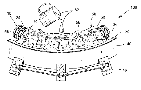
As illustrated in Figures 1, 2 and 4, an embodiment of a reusable
mold apparatus for manufacturing a surface patterned block (or mold form) is
shown generally at 100. Broadly speaking, the apparatus 100 includes a
5 support frame 11 and a resilient mold template 50 supported therein. A
setting
substrate 62 such as concrete, plaster and the like, is loaded into the
apparatus
100 and sets therein, as described in more detail below. The support frame 11
includes a first end member 10, a base member 26, a second end member 32,
a support panel 40 and a number of pushing blocks 46.
The first end member 10 is typically a hollow tube, which is
typically made of a polymer or plastic-like material such as those used in a
variety of purposes in the construction or plumbing industry. In this
embodiment, the hollow tube 10 is a flexible drainage tube, and a plurality of
spaced apart ridges 12 and recesses along substantially the entire length of
the
inner and outer surfaces of the tube 10. These features give the tube 10 both
resilience and rigidity. Depending on the desired shape of the block, the tube
10 can be manually straightened or bent to achieve a desired radius of
curvature R. The tube 10 includes first and second ends 14, 16 with a central
section 18 therebetween. The central section 18 includes respective concave
and convex sections 20, 22.
As shown in Figure 2, a cutaway (or recessed) portion 24 is
located in the convex portion 22 of the sidewafl in the tube 10. Typically,
the
cutaway section 24 is a rectangular concaved recess for receiving an amount of
setting material (or setting substrate) 62, as will be described below. The
cutaway portion 24 is of generally the same height H1 as the diameter of the
tube 10 and of an arcuate length L1. Located at both ends of the cutaway
portion 24 are two stoppers 13, which plug the tube 10 and prevent the flow of
setting substrate 62 away from the cutaway portion 24. One skilled in the art
will recognize that the base member 26 and the first end member 10 may be a
single piece of material. One may also envisage the template end portion 10 as
being a generally vertical wall orthogonal to the base member 26, so as to
CA 02456337 2004-02-06
6
produce blocks having straight edges, as opposed to the rounded edges that
are produced using the tube 10 described above.
In operation, the support frame 11 is temporarily constructed
according to the following description and with reference to Figures 2 and 4
The tube 10 is located on a work platform (not shown) and the base member
26, typically planar and made out of paperboard such as corrugated/reinforced
cardboard or the like, is positioned in a horizontal plane adjacent to the
tube 10.
The base member 26 is pre-cut to the desired swimming pool edge shape~and
serves as a basis for constructing the remaining elements of the mold
apparatus
100. The base member 26 has a width W1, a first edge 28 and a second edge
30 spaced apart from the first edge 28. The first and second edges 28, 30 are
generally curved and concentric with each other. The first edge 28 spans, at a
minimum, the arcuate length L1 and has an arcuate length L2, which generally
has the same radius R. The second edge 30 has an arcuate edge L3 of a
radius of curvature R' that is generally greater than the radius of curvature
R.
Typically, both lengths L2 and L3 encompass a same angle, and the length L3
is greater than L1 and greater than or equal to L2.
The second end member 32 is typically a pad, which is
connected to a first panel surface 42 of the support panel 40 using adhesive
or
some other securing means known to those skilled in the art. The pad 32 is
typically constructed from a resilient material, such as STYROFOAM T"" or the
like, that does not adhere to the setting substrate 62. The support panel 40
is
made from a resilient material, for example, composite wood board or the like.
The user positions and secures the hollow tube 10 on the base member 26.
The support panel 40 is positioned against the base second edge 30 and is
generally orthogonal to the base member 26. The pad 32 has a height H2 that
is typically slightly larger than the internal height H1 of the tube 10. The
pad 32
includes a first surface 34 that faces the base second edge 30. The first
surface
34 optionally includes a manually carved or trimmed surface pattern 36 having
irregularities that mimic naturally occurring surfaces such as those found on
stone. The pad 32 also includes a second surface 38, which is generally
smooth to allow for good contact with the support panel 40.
CA 02456337 2004-02-06
7
The support panel 40 is of a height H2 and includes a second
panel surface 44. The pushing blocks 46 (three are shown in Figure 1 ) are
connected to the second panel surface 44. When secured to the work surface
(not shown), the pushing blocks 46 ensure that the curvature of the pad 32
follows the radius R' of the template second edge 30 by applying an inward
retaining force against the support panel 40. The pad 32 and the support panel
40 are typically of the arcuate length L4, which is typically greater than L1,
L2
and slightly greater than L3. '
As illustrated in Figure 3, the user prepares the resilient mold
template 50 by applying layers of latex 48 onto a natural stone surface with a
desirable natural stone surface pattern. Optionally, a lubricant (not
illustrated)
may be applied to the stone surface to aid removal of the resilient mold
template
50. The layers of latex 48 are applied to form irregular relief patterns 54,
which
are the same as desirable natural stone surface pattern and which transfer the
surface patterns into a moldable surface of the block (or mold form) 68 as the
setting substrate sets. In the embodiment illustrated, the block 68 is a
coping
stone. The latex 48 typically has characteristics of drying without losing its
shape such that the irregular relief patterns 54 will remain essentially
intact.
One skilled in the art will recognize that regular patterns may also be added
to
transfer surface patterns such as letters, geometrical figures and the like,
to the
moldable block surface. One skilled in the art will also understand that other
types of material, which achieve the same function as latex, can be used.
As best illustrated in Figures 3 and 4, the layers of latex 48 have
a width W2 and a length L5. Before the latex layer 48 is completely dried, a
piece of cloth andlor reinforcing wire mesh 51 is laid over the latex layer 48
and
embeds itself into the surface of the latex layer 48. The cloth 51 is
typically
made out of cotton fabric, gauze or cheesecloth and the like. Additional
layers
of latex 48 are typically laid over the previous ones and over the cloth
and/or
wire mesh, which forms, after complete drying of the latex layers, a resilient
compounded template 52 with the relief patterns 54. The resilient compounded
CA 02456337 2004-02-06
8
template 52 is sufficiently dimensioned to allow it to be inserted into the
tube
cutaway portion 24.
As illustrated in Figure 4, when in use, the compounded template
52 covers the entire length L1 of the recessed end portion 24 of the concave
section 20 of the hollow tube 10, from the cutaway portion 24 to the base
second edge 30 over a length spanning, which is larger than the length L3. The
user locates or wraps the compounded template 52 inside the tube recessed
' end portion 24. The base member 26, the pad 32 and the tube 10 when
assembled form an opened-top and longitudinal end hollow mold 56 into which
the compounded template 52 is located. Openings 58, 60 are located on each
side of the hollow mold 56. A sufficient amount of the setting substrate 62 is
poured into the hollow mold 56 to ensure that its level reaches the height H1
and is supported and held in the support frame 11. The setting substrate 62,
during setting, includes at least one moldable surface that contacts the
relief
pattern 54 on the compounded template 52 and transfers the relief pattern 54
thereto as the setting substrate dries and sets.
As seen in Figure 5, once the setting substrate 62 has dried, the
block 68 with the surface pattern is removed from the hollow mold 56. The mold
apparatus 100 can be disassembled and re-used to produce mold forms of
different dimensions. The dried setting substrate 62 that has poured through
the openings 58, 60 is removed using a saw or the like, thus cutting the mold
form 68 to produce two straight, longitudinal smooth edges 64, 66.
As shown on Figure 5, the mold form 68 of height H1 results.
The mold form 68 is complementary to the internal dimensions of the reusable
mold apparatus 100. In the embodiment illustrated, the mold form 68 includes
first and second curved edge surfaces 70, 72, which generally follow the first
and second radii of curvature R and R', respectively, which substantially have
arcuate lengths L1 and L3 respectively. The first edge surface 70 has a convex
rounded shape, commonly called a "bull nose", along its length L1 as given by
the recessed end portion 24 of the tube concave section 20. The surface
pattern 36 of the pad 32 and the surFace relief pattern 54 of the compounded
CA 02456337 2004-02-06
9
cloth 52 are translated onto the corresponding edge surfaces 72, 70 of the
mold
form 68, as well as onto a mold form top surface 73. If required, further
surface
patterns can be applied to the mold form 68 by carving into the surfaces 70,
73
to create other patterns 74. The resulting mold form 68 has an improved
aesthetic appearance created by the relief patterns 54 and 74 and give surface
patterns similar to naturally occurring stone. Other irregularities in the pad
surface pattern 36 may also be transferred to an upper edge 72 of the mold
form 68. This gives the mold form 68 the appearance of being hand-cut. As is
well known in the art, the mold form 68 may then be used in a casting process
to produce a concrete replica coping stone of the mold form 68.
As shown in Figure 6, a series of coping stones 76, which are
produced by the method of the present invention, are shown positioned around
an upper edge 78 of an in-ground swimming pool. One skilled in the art will
recognize that the shape, dimensions and the surface patterns of the coping
stones 76 can be varied by changing the size and shape of the reusable mold
apparatus 100 and the compounded cloth 52. The coping stones 76 are
positioned over the edge 78 of the swimming pool and secured thereto, using
for example, bonding cement, mortar or glue. A waterproof sealant (not shown)
may also be injected between the two smooth edges 64, 66 of two adjacent
coping stones 76.
While a specific embodiment has been described, those skilled in
the art will recognize many alterations that could be made within the spirit
of the
invention, which is defined solely according to the following claims.