Some of the information on this Web page has been provided by external sources. The Government of Canada is not responsible for the accuracy, reliability or currency of the information supplied by external sources. Users wishing to rely upon this information should consult directly with the source of the information. Content provided by external sources is not subject to official languages, privacy and accessibility requirements.
Any discrepancies in the text and image of the Claims and Abstract are due to differing posting times. Text of the Claims and Abstract are posted:
| (12) Patent: | (11) CA 2456506 |
|---|---|
| (54) English Title: | ELECTRONIC CORE ORIENTATION DEVICE |
| (54) French Title: | DISPOSITIF ELECTRONIQUE D'ORIENTATION DE CAROTTE |
| Status: | Term Expired - Post Grant Beyond Limit |
| (51) International Patent Classification (IPC): |
|
|---|---|
| (72) Inventors : |
|
| (73) Owners : |
|
| (71) Applicants : |
|
| (74) Agent: | NATHAN V. WOODRUFFWOODRUFF, NATHAN V. |
| (74) Associate agent: | |
| (45) Issued: | 2006-11-21 |
| (22) Filed Date: | 2004-02-03 |
| (41) Open to Public Inspection: | 2005-01-03 |
| Examination requested: | 2004-10-06 |
| Availability of licence: | N/A |
| Dedicated to the Public: | N/A |
| (25) Language of filing: | English |
| Patent Cooperation Treaty (PCT): | No |
|---|
| (30) Application Priority Data: | None |
|---|
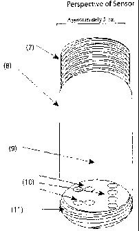
This invention provides a low cost, accurate and reliable core orientation method for inclined holes. The system consists of a sensor, display unit, specialized core tube, core tube alignment clip and where necessary, a customized drill rod extension. The sensor's components are: 3-axis accelerometer, clock, power source, programming and memory circuitry, shock absorbers and data transfer system, all encased in a standard diameter core tube extension. This sensor is attached to the top of the specialized core barrel during drilling. The sensor takes readings for core rotation and core inclination data for each core run, which may be used for other survey purposes. The specialized core barrel is aligned with the sensor, to facilitate accurate marking of the retrieved core. The display unit retrieves the core orientation data from the sensor and stores it on a memory card.
L'invention fournit une méthode d'orientation de carotte fiable, précise et bon marché pour les trous inclinés. Le système consiste d'un capteur, une unité d'affichage, un tube carottier spécialisé, une agrafe d'alignement de tube carottier et là où nécessaire, une extension de tige de forage. Les composants du capteur sont : accéléromètre à 3 axes, horloge, source d'alimentation, circuiterie de programmation et de mémoire, amortisseurs, et système de transfert de données, le tout emboîté dans une extension de tube carottier de diamètre standard. Le capteur est attaché sur le haut du carottier spécialisé pendant le forage. Le capteur prend des mesures pour la rotation de la carotte et des données d'inclination de carotte pour chaque fonctionnement de la carotte, ce qui peut être utilisé à d'autres fins d'enquête. Le carottier spécialisé est aligné avec le capteur pour faciliter le marquage précis de la carotte récupérée. L'unité d'affichage récupère les données d'orientation de la carotte du capteur et les stocke sur une carte mémoire.
Note: Claims are shown in the official language in which they were submitted.
Note: Descriptions are shown in the official language in which they were submitted.
2024-08-01:As part of the Next Generation Patents (NGP) transition, the Canadian Patents Database (CPD) now contains a more detailed Event History, which replicates the Event Log of our new back-office solution.
Please note that "Inactive:" events refers to events no longer in use in our new back-office solution.
For a clearer understanding of the status of the application/patent presented on this page, the site Disclaimer , as well as the definitions for Patent , Event History , Maintenance Fee and Payment History should be consulted.
| Description | Date |
|---|---|
| Inactive: Expired (new Act pat) | 2024-02-05 |
| Letter Sent | 2023-04-11 |
| Inactive: Multiple transfers | 2023-03-24 |
| Inactive: Office letter | 2019-12-23 |
| Common Representative Appointed | 2019-10-30 |
| Common Representative Appointed | 2019-10-30 |
| Revocation of Agent Requirements Determined Compliant | 2019-07-16 |
| Appointment of Agent Requirements Determined Compliant | 2019-07-16 |
| Revocation of Agent Requirements Determined Compliant | 2019-05-14 |
| Inactive: Office letter | 2019-05-14 |
| Inactive: Office letter | 2019-05-14 |
| Appointment of Agent Requirements Determined Compliant | 2019-05-14 |
| Appointment of Agent Request | 2019-05-07 |
| Revocation of Agent Requirements Determined Compliant | 2019-05-07 |
| Appointment of Agent Requirements Determined Compliant | 2019-05-07 |
| Revocation of Agent Request | 2019-05-07 |
| Appointment of Agent Request | 2019-05-07 |
| Revocation of Agent Request | 2019-05-07 |
| Letter Sent | 2017-04-10 |
| Inactive: Correspondence - Transfer | 2017-03-20 |
| Inactive: Agents merged | 2015-11-11 |
| Letter Sent | 2010-03-10 |
| Inactive: Office letter | 2010-02-23 |
| Letter Sent | 2009-12-22 |
| Inactive: Single transfer | 2009-12-02 |
| Inactive: Single transfer | 2009-11-02 |
| Inactive: Late MF processed | 2009-06-01 |
| Letter Sent | 2009-02-03 |
| Inactive: Late MF processed | 2008-04-07 |
| Letter Sent | 2008-02-04 |
| Revocation of Agent Requirements Determined Compliant | 2006-12-18 |
| Inactive: Office letter | 2006-12-18 |
| Inactive: Office letter | 2006-12-18 |
| Appointment of Agent Requirements Determined Compliant | 2006-12-18 |
| Letter Sent | 2006-12-12 |
| Letter Sent | 2006-12-12 |
| Appointment of Agent Request | 2006-12-06 |
| Revocation of Agent Request | 2006-12-06 |
| Inactive: Single transfer | 2006-12-06 |
| Grant by Issuance | 2006-11-21 |
| Inactive: Cover page published | 2006-11-20 |
| Revocation of Agent Requirements Determined Compliant | 2006-09-14 |
| Change of Address Requirements Determined Compliant | 2006-09-14 |
| Appointment of Agent Requirements Determined Compliant | 2006-09-14 |
| Inactive: Office letter | 2006-09-14 |
| Inactive: Office letter | 2006-09-14 |
| Inactive: Adhoc Request Documented | 2006-09-13 |
| Pre-grant | 2006-09-06 |
| Inactive: Final fee received | 2006-09-06 |
| Inactive: Final fee received | 2006-09-06 |
| Revocation of Agent Request | 2006-09-06 |
| Appointment of Agent Request | 2006-09-06 |
| Change of Address or Method of Correspondence Request Received | 2006-09-06 |
| Notice of Allowance is Issued | 2006-07-17 |
| Letter Sent | 2006-07-17 |
| Notice of Allowance is Issued | 2006-07-17 |
| Inactive: Approved for allowance (AFA) | 2006-06-28 |
| Revocation of Agent Requirements Determined Compliant | 2006-05-24 |
| Inactive: Office letter | 2006-05-24 |
| Inactive: Office letter | 2006-05-24 |
| Appointment of Agent Requirements Determined Compliant | 2006-05-24 |
| Appointment of Agent Request | 2006-05-11 |
| Amendment Received - Voluntary Amendment | 2006-05-11 |
| Revocation of Agent Request | 2006-05-11 |
| Inactive: IPC from MCD | 2006-03-12 |
| Inactive: S.30(2) Rules - Examiner requisition | 2005-11-23 |
| Amendment Received - Voluntary Amendment | 2005-06-20 |
| Inactive: S.30(2) Rules - Examiner requisition | 2005-01-17 |
| Application Published (Open to Public Inspection) | 2005-01-03 |
| Inactive: Cover page published | 2005-01-02 |
| Advanced Examination Determined Compliant - paragraph 84(1)(a) of the Patent Rules | 2004-11-03 |
| Letter sent | 2004-11-03 |
| Inactive: Office letter | 2004-11-02 |
| Early Laid Open Requested | 2004-11-02 |
| Letter Sent | 2004-10-18 |
| Inactive: Advanced examination (SO) | 2004-10-06 |
| Request for Examination Requirements Determined Compliant | 2004-10-06 |
| Inactive: Advanced examination (SO) fee processed | 2004-10-06 |
| All Requirements for Examination Determined Compliant | 2004-10-06 |
| Request for Examination Received | 2004-10-06 |
| Inactive: Correspondence - Formalities | 2004-03-26 |
| Inactive: First IPC assigned | 2004-03-23 |
| Inactive: IPC assigned | 2004-03-23 |
| Inactive: Office letter | 2004-03-10 |
| Inactive: Filing certificate - No RFE (English) | 2004-03-08 |
| Filing Requirements Determined Compliant | 2004-03-08 |
| Application Received - Regular National | 2004-03-08 |
There is no abandonment history.
The last payment was received on 2006-01-09
Note : If the full payment has not been received on or before the date indicated, a further fee may be required which may be one of the following
Please refer to the CIPO Patent Fees web page to see all current fee amounts.
Note: Records showing the ownership history in alphabetical order.
| Current Owners on Record |
|---|
| REFLEX INSTRUMENT NORTH AMERICA LIMITED |
| Past Owners on Record |
|---|
| DAVE SCOTT |

