Note: Descriptions are shown in the official language in which they were submitted.
CA 02457335 2004-02-10
MULTIPLE PLASMA GENERATOR HAZARDOUS
WASTE PRQCESSING SYSTEM
BACKGROUND OF THE INVENTION
Field of the Invention
[0001 ] This invention relates to a method and a system for the disposal of
waste
and/or hazardous materials waste.
DESCRIPTION OF THE PRIOR ART
[0002] A major problem facing modern society is the disposal of toxic waste
and/or
hazardous materials in a manner which minimizes harmful effects on the
environment.
Such a disposal system is one which is capable of reducing such toxic and/or
hazardous
waste to compounds which are suitable for environmental disposal. Such
suitability is, of
course, defined in terms of acceptable levels of pollution, and is determined
by a variety of
regulatory agencies.
[0003[ Traditionally, hazardous waste disposal has taken the form of direct
burial in
landfills, or simple thermal processing of the waste, followed by burial of
the solid residue,
and release to the atmosphere of the volatile residue. None of these
approaches have
proven acceptable, due to the fact that the materials which are released to
the environment
tend to remain as unacceptable sources of pollution.
[0004[ Another normal approach for a system for the disposal of waste and/or
hazardous materials is to apply a single heat source into a confined space in
an apparatus
on the assumption that the temperature within the reactor vessel of the
processing system
will be uniform. This assumption is without knowledge of potential cold spots
which can
develop within the reactor vessel of the processing system. Such systems
normally gasify
all of the input waste constituents; however, they do not guarantee that all
such gaseous
elements are subjected to the total temperature environment which is necessary
to ensure
total and effective destruction of the more hazardous of the waste and/or
hazardous
materials. A single heat source which is provided at the center of the reactor
vessel
processing system can create paths close to the refractory wall of the reactor
vessel of the
processing system whereby gaseous elements can traverse without being
subjected to the
CA 02457335 2004-02-10
required temperature/residence time combination for complete breakdown. Also,
the
generation of gaseous elements within the reactor vessel from the gasification
process can
very dramatically alter the gas flow pattern within the reactor vessel. 'This
can result in
gaseous hazardous compounds being exhausted from the reactor vessel and/or not
fully
processed waste constituents being transferred to slag. Downstream combustion
does not
achieve the full temperature capability of certain processing systems, i.e.,
plasma
processing systems. Therefore, hazardous gaseous compounds being exhausted
from the
reactor vessel of the processing system result in abnormal complexity through
gas handling
and potentially excessive pollutants being exhausted to the atmosphere. Not
fully processed
waste in slag can result in some or all of this hazardous material remaining
in the slag after
the slag is extracted from the reactor vessel. This may mean that the slag
exceeds leachate
toxicity limits and, thereby, remains as a hazardous waste requiring continued
special
disposal or storage requirements.
[0005) Other processing systems for the disposal waste and/or hazardous
materials
attempt to overcome these shortcomings by dramatically increasing the overall
reactor
vessel temperature using plasma arc generators, thus ensuring that the minimum
temperature encountered throughout the reactor vessel processing chamber is
sufficient for
adequate thermal decomposition of all waste constituents. This approach solves
the
problem of insu~cient exposure of some waste constituents to the high
temperature which
is necessary to achieve good thermal decomposition. However, in so doing, it
also creates
other problems, including increased plasma generator electrode erosion,
decreased reactor
vessel refractory life, increased heat losses, increased electricity
consumption, increased
cooling load for the gas handling system and increased volatilization of
pollutant elements,
particularly heavy metals. The resultant higher temperature product gas on
exit is not only
wasteful of plasma arc generator power, but is also very conducive to
increased hazardous
pollutants. Such problems aggregate dramatically to reduce overall system
processing
efficiency and cost effectiveness.
(OOOb[ A number of approaches have thus been developed for disposing of
industrial waste products. The patent literature is replete with alleged such
solutions.
[0007) U.S. Patent No. 3,766,866, issued October 23, 1973 to Krwn, taught a
thermal waste converter with primary and secondary chambers for the pyrolysis
and
combustion of waste material. Thus, this patent provided apparatus for the
recycling of
CA 02457335 2004-02-10
3
waste material having a pyrolyzing chamber for the gasification of waste
material including
an inlet for the waste and an outlet for the gas produced therefrom. An
independent
secondary chamber had an inlet for gas from the pyrolyzing chamber and an
outlet for
gases of combustion. Means connected the outlet of the pyrolyzing chamber to
the inlet of
the secondary chamber. Means directed solid residues from the pyrolyzing
chamber to the
secondary chamber. A burner in the secondary chamber burned combustible gas
which is
produced in the pyrolyzing chamber to reduce the solid residue in the
secondary chamber
to a molten condition.
(0008] U.S. Patent No. 4,438,706, issued March 27, 1984 to Boday, provided an
attempt to destroy waste material using direct current (DC) arc discharge type
plasma
torches. This patent taught the use of DC arc discharge plasma torch in
combination with
an oxidizing agent for the thermochemical decomposition of certain types of
waste
material. The torch gas was air, and the waste material in vapor form was
introduced along
with oxygen downstream of the plasma arc generator, where it was heated by the
torch gas.
The method included transferring plasma into a plasma torch at one end of a
plasma
reactor. The method included introducing organic waste vapor and preheated
oxygen into
the torch for interaction with the plasma. The method finally included
discharging end
products of the interaction from the end of the plasma reactor, opposite to
the location of
the torch, into gas washing equipment.
[0009] Faldt, et al, U.S. Patent No. 4,479,443, issued October 30, 1984,
disclosed
the use of an arc discharge plasma torch thermally to decompose waste
material. Waste
material in the form of solid particles were introduced downstream of the arc
to avoid
fouling of the torch as a result of particle adherence. Oxidizing agents,
e.g., oxygen and air,
were mixed with the waste either before, during or after the waste was heated
by the torch
gas. Sufficient oxidizing agents were required for the complete oxidation of
the waste
material. The apparatus included a plasma generator far producing a high
temperature
plasma in which all molecules of the plasma reach at least a desired minimum
temperature.
The apparatus included means for feeding hazardous waste to and through the
plasma
generator. The apparatus included means for feeding sufficient oxidizing
agents to the
hazardous waste to permit the complete decomposition of the hazardous waste to
stable
products. The apparatus included means for controlling the temperature of the
plasma and
the flow of hazardous waste through the plasma generator so that the hazardous
waste can
CA 02457335 2004-02-10
4
reach a sufficiently high temperature for a suffcient period of time thepmally
to decompose
completely to stable final products.
[0010) Barton, et al, U.S. Patent No. 6,644,877, issued October 30, 1984,
disclosed
the use of a DC arc plasma burner for the pyrolytic decomposition of waste.
Provisions
were made for feeding waste material downstream of the arc electrodes to
prevent
interference with the formation or generation of the plasma arc. A reaction
chamber
following the burner was used to combine gas and particulate matter, which is
quenched
and neutralized with an alkaline spray. A mechanical scrubber was used to
separate gases,
which are withdrawn using an exhaust fan. The apparatus included a plasma
burner having
a temperature in excess of 5,000° C. The apparatus included a reaction
vessel connected to
the plasma burner and having a refractory lined reaction chamber for receiving
the plasma
arc. The apparatus included means for inserting waste material directly into
the plasma arc
in the co-linear electrode space to be atomized and ionized under
substantially pyrolytic
conditions and then recombined into recombined products in the reaction
chamber. The
apparatus included an outlet for removing the recombined products therefrom.
[0011 ) Chang, et al U.S. Patent No. 4,886,001, issued December 12, 1989,
provided
apparatus for pyrolytically decomposing waste material. 'The apparatus
included a plasma
torch to produce a plasma having an operating temperature of at least
5000° C for
destroying a solution of a waste material to form a mixture of gases and solid
particulate.
The torch was combined with means for introducing the waste material in an
atomized
state. The apparatus included a recombination chamber for receiving and
separating the
mixture of gases and solid particulate. The apparatus included a solid
separator for
providing a partial vacuum for removing any carryover gases from the solid
particulate.
[0012) U.S. Patent No. 5,256,854, issued February 22, 1994 to Bromberg et al,
taught a method and apparatus for simultaneously bombarding toxic gases with
high energy
electron irradiation and rf inductive fields to destroy vaporized toxic
materials. Thus, this
patent provided a two-chamber system for destroying toxic waste comprising a
first
chamber adapted to heat and vaporize the toxic waste and a second chamber
adapted to
receive gases from the first chamber. The second chamber was used to break
down toxic
molecules in the gases via a tunable combination of simultaneous and
continuous inductive
heating and electron beam irradiation at no less than atmospheric pressure and
at
temperatures lower than those required to destroy toxic waste by inductive
heating alone.
CA 02457335 2004-02-10
[0013] U.S. Patent No. 5,288,969, issued Febnaary 22, 1994 to Wong et al,
taught
an inductively coupled rf plasma torch technology operating at atmospheric
pressures for
the dislocation of hazardous waste. 'Thus, this patent provided apparatus
which included a
source of waste material to be processed. The apparatus included a source of
gas capable of
forming free electrons in a plasma when excited to a high temperature. The
apparatus
included combining means for combining the waste material with the gas. The
apparatus
included a reactor chamber. The apparatus included means for transporting the
combination
of the waste material and the gas through the reactor chamber. The apparatus
included
excitation means for exciting the gas in the reactor chamber with
electromagnetic energy to
form a plasma including free electrons, wherein the excitation means comprised
an RF
plasma torch. The apparatus included timing means for maintaining the free
electrons at the
raised temperature level in the reactor chamber for a sufficient time to
dissociate the waste
material.
(0014] U.S. Patent No. 5,541,386, issued July 30, 1996, to Mui et al, provided
a
system and method for the disposal of waste material including water, volatile
components
and vitrifiable components. The waste material was heated in a dehydrator to
remove the
water, was then heated in a high temperature dryer to vaporize hydrocarbon
liquids, and
then was fed to the focus point of a primary plasma reactor where plasma arc
jets were
focused on the surface of a pool of the vitrifiable components. At the focus
point, the
vitrifiable components were melted, and the volatile components are volatized.
The melted
components were received in a quench chamber where they solidified on a quench
roller
and were broken into chips and delivered to a receiving area. Heat from the
quench
chamber was transferred to the dehydrator and high temperature dryer. The
hydrocarbon
liquids and volatized components were fed to a secondary plasma reactor where
they were
disassociated into their elemental components. The effluent from the secondary
plasma
reactor was scrubbed to remove hydrogen sulfide and halogens, and residual
components,
together with excess water vapor, were extracted in an absorber and fed back
for further
processing in the secondary plasma reactor.
[0015[ U.S. Patent No. 5,779,991, issued July 14, 1998 to Jerkins, taught an
apparatus for destroying hazardous compounds in a gas stream using a
cylindrical labyrinth
passage wherein a plurality of electric fields were used for generating and
sustaining a
plasma or corona discharge through different zones within the gas labyrinth.
Thus, this
CA 02457335 2004-02-10
6
patent provided a mobile waste incinerator which included separate first and
second zones,
the first zone having a first Iive electrode and a ground electrode, the
electrode including a
first compartment and a second compartment. The mobile waste incinerator
included
means for exciting the first live electrode at a first electrical energy level
for generating,
with the first compartment, a first electric field and for generating a plasma
in the waste gas
when the waste gas was flowing through the first gas passage. The mobile waste
incinerator included a second zone having a second live electrode mounted
inside and
spaced apart from the second compartment and defining, with said second
compartment, a
second gas passage communicating with the downstream end of the first gas
passages. The
mobile waste incinerator included means for exciting the second live electrode
at a second
electrical ener~r level for generating, with the second compartment, a second
electric field
capable of sustaining the plasma in the waste gas when the waste gas was
flowing through
said second gas passage. The mobile waste incinerator included means for
generating a
third electric field between the second live electrode and the first live
electrode for
providing a complementary source of electrical energy between the first and
second electric
fields for sustaining the plasma between the first and the second zones.
(0026] U.S. Patent No. 5,798,496, issued April 22, 2003, to Eckhoff et al,
taught a
mobile plasma-based waste disposal system which utilized an arc-torch plasma
technology
to dispose of industrial waste. The portable reactor included a rotatable kiln
comprising an
upper end for introduction of waste material and a lower end, said rotatable
kiln mounted
on a movable vehicle. It included a breech disposed adjacent the lower end of
the kiln, at
least one of the breech and lower end forming an outlet for discharge of
pyrolytically
treated waste material. It includes at least two plasma guns attached to the
breech and
disposed so as to direct an arc into the kiln. It included at feast two target
electrodes spaced
from the plasma guns and attached to at least one of the breech an the kiln.
At least one of
the plasma guns and at least one of the target electrodes was movable.
(0017] U.S. Patent No. 6,552,295, issued April 22, 2003, to Markunas et al
provided a method and apparatus for plasma waste disposal of hazardous waste
material,
where the hazardous material was volatilized under vacuum inside a containment
chamber
to produce a pre-processed gas as input to a plasma furnace including a plasma-
forming
region in which a plasma-forming magnetic field was produced. 'The pre-
processed gas was
passed at Iow pressure and without circumvention through the plasma-forming
region and
CA 02457335 2004-02-10
7
was directly energized to an inductively-coupled plasma state such that
hazardous waste
reactants included in the pre-processed gas were completely dissociated in
transit through
the plasma-forming region. Preferably, the plasma-forming region was shaped as
a vacuum
annulus and was dimensioned such that there was no bypass by which hazardous
waste
reactants in the pre-processed gas can circumvent the plasma-forming region.
The plasma
furnace was powered by a high frequency power supply outputting power at a
fundamental
frequency. The power supply contained parasitic power dissipation mechanisms
to prevent
non-fundamental, parasitic frequencies from destabilizing the fundamental
frequency
output power.
SUMMARY OF THE INVENTION
[0018] The prior art plasma waste decomposition systems described above
suffered
from a variety of shortcomings. One shortcoming results from the fact that the
waste
material generally cannot be introduced directly into the plasma arc because
such
introduction causes contamination of the arc electrodes and subsequent erratic
operation of
the arc. Thus, the waste material was introduced downstream of the arc and was
indirectly
heated by the torch gas. This technique shortened the high temperature
residence time of
the waste material, resulting in incomplete decomposition.
[0019] Further, the performance of the plasma arc is highly sensitive to the
flow
rate of the waste and carrier gas. 'Thus, the flow rates must be confined
within narrow
limits, leading to difficulties in controlling and maintaining system
performance. Arc
electrode erosion with use further complicated the maintenance, operation,
stability and
safety of the system. Small scale operation of DC arc plasmas was also very
inefficient due
in part to the minimum gas flow rate and electric power requirements needed to
strike
initiate and sustain the arc. Scaling the prior art systems for operation at
different waste
throughput levels and with a variety of waste materials has proven to be
difficult, requiring
major system configuration changes which are expensive to accomplish.
[0020] Additionally, the need for organic, oxidizing, and/or reducing agents
to be
confined with the waste material in the prior art systems often resulted in
highly
undesirable compounds in the waste residue.
CA 02457335 2004-02-10
g
(0021 ] In summary, none of the prior art systems have provided a consistent
method of reducing all types and forms of hazardous waste to compounds which
were
suitable for environmental disposal.
[0022] It is therefore an object of a broad aspect of the present invention to
address
these shortcomings and to provide hazardous waste processing systems and
methods which
ensure total destruction of all hazardous constituents while maintaining a low
input power
level and a long refractory life.
STATEMENTS OF THE INVENTION
[0023] One broad embodiment of the present invention provides an apparatus for
the disposal of waste and/or hazardous materials. The apparatus includes a
refractory-lined
reactor vessel. The apparatus includes plasma-generating means within the
refractory-lined
reactor vessel for producing a high temperature plasma processing zone which
has a
substantially-uniform high temperature across the entire periphery of the
refractory-lined
reactor vessel. The plasma-generating means includes at least one fixed-
position plasma arc
generator, and at least one movable plasma arc generator. The apparatus
includes first
feeding means for feeding the waste and/or hazardous materials to, and
through, the high
temperature plasma processing zone. The apparatus includes second feeding
means for
feeding sufficient process additive agents to the high temperature plasma
processing zone
to cause the complete decomposition of the waste and/or hazardous materials
and the
formation of stable, non-hazardous materials. The apparatus includes
controlling means for
controlling the plasma arc generating means and the flow of the waste and/or
hazardous
materials through the high temperature plasma processing zone to assure that
all the waste
and/or hazardous material reaches a sufficiently high temperature, and for a
su~cient
period of time, thermally to fully decompose the waste and/or hazardous
materials into
very small ions. Adequate process addirives are made available to establish
the optimum
chemical equilibrium that will convert the decomposition products into stable
non-
hazardous final products. The apparatus includes gas removal means for
removing product
gas from the reactor vessel. The apparatus includes monitoring means for
monitoring the
gas stream to determine the amount of particulate matter in the product gas
stream. The
apparatus includes solids removing means for removing solid stable non-
hazardous final
product in a lava like state from the apparatus.
CA 02457335 2004-02-10
9
[0024] A second broad embodiment of the present invention provides a method
for
the disposal of waste and/or hazardous materials. The method includes
providing a
refractory-lined cylindrical reactor vessel with plasma-generating means
within the
refractory-lined reactor vessel and producing a high temperature plasma
processing zone
therein which has a substantially-uniform high temperature across the entire
periphery of
the refractory-lined reactor vessel, by way of plasma-generating means which
includes at
least one fixed-position plasma arc generator, and at least one movable plasma
arc
generator. The method includes feeding, preferably continuously, solid and/or
liquid waste
and/or hazardous materials to, and through, the high temperature plasma
processing zone.
The method includes selectively, preferably continuously, feeding sufficient
process
additive agents to the high temperature plasma processing zone, for completely
decomposing the waste andlor hazardous materials and to form stable, non-
hazardous
materials. The method includes removing, preferably continuously, gaseous
products from
the refractory lined reactor vessel. The method includes monitoring,
preferably
continuously, the gaseous products to determine the amount of particulate
material in the
gaseous products. The method includes removing solid stable non-hazardous
final product
from the refiactory-lined reactor vessel.
OTHER FEATURES OF THE INVENTION
[0025] By a first feature of the apparatus embodiment of the present invention
the
at least one fixed position plasma arc generator is a plurality of, e.g., two,
fixed position
plasma arc generators, which are disposed within the refractory-lined reactor
vessel from
opposite sides thereof, with angular displacement relative to each other in
order for their
plasma plumes to intersect at a focal point which is near the center of the
waste and/or
hazardous material input into the apparatus.
[0026] By a second feature of the apparatus embodiment of the present
invention,
the at least one movable plasma arc generator is a single moveable plasma arc
generator
which is mounted at the top of the refractory-lined reactor vessel and which
has three
degrees of freedom to permit aiming towards the focal point of the plasma arc
plumes from
the fixed position plasma arc generators or towards the molten slag pool.
[0027] By a third feature of the apparatus embodiment of the present
invention, the
first feeding means comprises a plurality of waste and/or hazardous material
feed ports,
CA 02457335 2004-02-10
each of which is configured to feed directly towards the focal point of the
plasma arc
plumes from the fixed position plasma arc generators.
[0028] By a fourth feature of the apparatus embodiment of the present
invention,
the gas removal means and the solids removal means are ports which are
diametrically
opposite to the first feeding means.
[(1029] By a fifth feature of the apparatus embodiment of the present
invention, the
apparatus includes at least one port for the injection of steam towards a
point which is just
past the intersection focal point of the plasma arc plumes from the fixed
position plasma
arc generators, on the opposite side from the feed inlet. It also includes a
steam injection
port covering the gas exit area.
[0030] By a sixth feature of the apparatus embodiment of the present
invention, the
feeding means comprises a plurality of air inlet ports disposed in spaced-
apart relation
around the refractory-lined reactor vessel.
[0031 ] By a seventh feature of the apparatus embodiment of the present
invention,
the gas removal means comprises a gas outlet conduit which is configured to
produce an
exit velocity of the gas conducive for airborne solids to fall back into the
reactor vessel
rather than be carried out of the reactor vessel by the exiting gas stream.
[0032] By an eighth feature of the apparatus embodiment of the present
invention, a
lower section of the refi~actory-lined reactor vessel is flanged to enable
connection of a
removable bottom element to the remainder of the refiactory-lined reactor
vessel to
facilitate opening.
[0033) By a ninth feature of the apparatus embodiment of the present
invention, the
refractory lining comprises materials similar to A.P. Green G26LI, G23LI,
G20LI and
Insulblok 19.
[0034) By a tenth feature of the apparatus embodiment of the present
invention, a
lower section of the refractory-lined reactor vessel consists of a not face
refiactory, the hot
face refractory comprising materials similar to RADEX COMPAQ-FLO V253 or
DIDIER
RK30.
[0035] By an eleventh feature of the apparatus embodiment of the present
invention, the apparatus includes optional water cooling means for the lower
section of the
refractory-lined reactor vessel.
CA 02457335 2004-02-10
11
[0036] By a twelfth feature of the apparatus embodiment of the present
invention,
the monitoring means includes sensors which are configured to determine the
opacity of
the exit gas stream.
(0037( By a thirteenth feature of the apparatus embodiment of the present
invention, the sensors are maintained essentially-deposit free by a nitrogen
purge element
which is configured to provide a flow of nitrogen across the face of the
sensors.
[0038] By a fourteenth feature of the apparatus embodiment of the present
invention, the sensors are maintained essentially-deposit free by an element
which is
configured to maintain a negative pressure in the region of the sensors.
(0039] By a fifteenth feature of the apparatus embodiment of the present
invention,
the apparatus also includes a removable preheat burner within the refractory-
lined reactor
vessel.
[0040[ By a sixteenth feature of the apparatus embodiment of the present
invention,
the refi~actory-lined reactor vessel is cylindrical.
(0041 ] By a first feature of the method embodiment of the present invention,
the
method includes disposing the at least one movable plasma arc generator in
close proximity
to the ports which feed the waste and/or hazardous materials to, and through,
the high
temperature plasma processing zone.
[0042] By a second feature of the method embodiment of the present invention,
the
method further includes injecting steam towards the high temperature plasma
zone and
towards the gas exit area.
[0043] By a third feature of the method embodiment of the present invention,
the
method comprises disposing air inlet ports in spaced-apart relation around the
refiactory-
lined cylindrical vessel and selectively feeding the process additive agents
into the high
temperature plasma processing zone through the inlet ports
[0044[ By a fourth feature of the method embodiment of the present invention,
the
method further comprises creating an exit velocity of the gaseous products
which is
conducive for airborne solids to fall back into the reactor vessel as opposed
to being carried
out of the reactor vessel by the exiting gas stream.
[0045] By a fifth feature of the method embodiment of the present invention,
the
method includes the option of cooling a lower section of the refiactory-lined
cylindrical
vessel.
CA 02457335 2004-02-10
12
(0046] By a sixth feature of the method embodiment of the present invention,
the
method includes monitoring of the gaseous products by determining the opacity
of the
gaseous products by opacity sensors.
[0047] By a seventh feature of the method embodiment of the present invention,
the
method fiuther comprises maintaining the opacity sensor elements essentially
deposit free
by flowing a stream of nitrogen across the face of the sensor elements.
[0048] By an eighth feature of the method embodiment of the present invention,
the
method fiuther comprises maintaining the opacity sensors essentially deposit
free by
maintaining a negative pressure in the region of the sensors.
[0049] By a ninth feature of the method embodiment of the present invention,
the
method further comprises the first step of preheating the refractory-lined
cylindrical vessel
by means of a removable burner system.
GENERALIZED DESCRIPTION OF THE INVENTION
[0050] The present invention preferably entails the use ofmultiple, e.g., two,
fixed
position plasma arc generators for primary processing and a single movable
plasma arc
generator for secondary or processing assistance and/or for final conditioning
of the slag
prior to exit from the apparatus, i.e., reactor vessel. As will be described
hereinafter, the
present invention provides control of reactor vessel geometry to ensure
maximum
processing efficiency. Positioning and operation of the plasma arc generators
provides for a
high temperature processing zone where it is optimally required, as well as to
provide
adequate heat concentration to melt and force the slag to flow, in addition to
achieving the
lowest possible product gas temperature at the product gas exit port.
j0051] Most complete breakdown of waste and/or hazardous materials is achieved
if a high temperature processing zone is maintained as a solid wall across the
entire
periphery of the reactor vessel to ensure that all input waste and/or
hazardous materials are
forced to go through it. In aspects of the present invention, the fixed
position plasma arc
generators for primary processing are provided in the reactor vessel at
opposite sides of the
reactor vessel with angular displacement relative to each other and aimed to
permit their
plasma plumes to intersect at a focal point and provide fullest temperature
coverage of the
hazardous waste feeder opening into the reactor vessel. The focal point of the
plasma arc
plumes from these plasma arc generators is preferably fixed near the center of
the input
CA 02457335 2004-02-10
13
waste. They can also be adjusted so as to ensure the maintenance of the
optimal high
temperature processing zone as well as to induce advantageous gas flow
patterns around
the entire reactor vessel. The moveable plasma arc generator is preferably
mounted in the
top of the reactor vessel and possesses three degrees of freedom to permit
aiming of its
plasma arc plume at, or around, the intersection of the plasma arc plumes from
the fixed
position plasma arc generators to provide secondary, or assisted processing
should the need
arise. It may also permit aiming of its plume towards the slag pool at, or
around, the slag
exit port for slag conditioning. Secondary processing assistance from the
moveable plasma
arc generator is advantageous through periods of lowering processing
temperature due to
unexpected changes in the chemical composition characteristics of the input
waste and/or
hazardous material. Slag conditioning is essential to ensure that the slag
exit port remains
open through the complete slag extraction period and to maintain the slag as
homogeneous
as possible to guard against the possibility that some incompletely-processed
material may
inadvertently make its way out of the reactor vessel during slag extraction.
All plasma arc
generators may be operated on a continuous basis at the discretion of the
operator.
[0052] The reactor vessel physical design characteristics are determined by a
number of factors, namely:
[0053) Firstly, the chemical composition of the waste and/or hazardous
material
stream to be processed. The internal configuration and size of the reactor
vessel are
dictated by the operational characteristics through analyses of the input
waste stream to be
processed.
[0054] Secondly, the plasma arc generators. The plasma arc generators must be
positioned within the reactor vessel at the desire depth in order to
concentrate the high
temperature processing zone where it will be most effective, while at the same
time
minimizing plasma arc generator heat loses.
[0055] Thirdly, the position and orientation of the plasma arc generators. The
plasma arc generators must be positioned, and their plasma heat must be
directed, in such a
way as to ensure an adequate travel path for all gaseous molecules produced.
This is to
maintain a sufficient residence time in the high temperature processing zone
to guarantee
their full decomposition, and conversion into the smallest and most non-
polluting
molecules.
CA 02457335 2004-02-10
14
[0056] Fourthly, the position, orientation and number of the process additive
injection ports. The process additives must be injected where they will ensure
most
efficient reaction to achieve the desired conversion result.
[0057] The waste feed location, the plasma arc generators insertion depth,
their
position and orientation, and the position, orientation and number of the
process additive
ports are all important in establishing the desired flow and temperature
distribution features
that are critical in minimizing refractory erosion with the best possible
compromise of a
temperature profile, i.e. very high temperature processing zone, high
temperature slag
melting/tapping zone and medium temperature gas exit. This generalized
description of the
present invention may be represented by an embodiment which includes the
following
features with the overall objective of
1. fizll decomposition of the waste in order to achieve minimization of
pollutants;
2. fiill melting and homogenization of the slag; and
3. minimization of exhaust heat loses.
[0058] The embodiment includes two opposing side mounted plasma arc generators
with center line angular displacement and a combined plasma arc plume fixed
focal point
close to the center of the input waste and/or hazardous material stream. The
angular
displacement provides for turbulence within the input waste and the generated
product gas
substantially to assist in the efficiency of processing. The fixed focal point
generates a total
wall of high temperature processing zone through which all elements of the
input waste are
forced to pass.
[0059] The embodiment includes a top mounted plasma arc generator with three
degrees of freedom to permit the plasma arc plume from this generator to be
directed to
supply plasma heat in support of the side mounted processing plasma arc
generators, or to
be directed to be concentrate on the slag pool at and around the slag exit
port. This plasma
arc generator is mounted at the rear of the reactor vessel, diametrically
opposite to the
incoming waste front and in close proximity to the by-product exit ports to
ensure the
maintenance of the full required processing temperature for both of the
process by-
products.
CA 02457335 2004-02-10
[0060] The embodiment includes a plurality of input waste feed ports to cater
to
any physical characteristics of the input waste and/or hazardous waste
materials, each of
which feed directly into the high temperature processing zone focal area as
created by the
plasma arc plumes from the side mounted plasma arc generators.
[0061] The embodiment includes slag exit port and product gas outlet conduit
diametrically opposite to the feed ports to ensure the maximum path possible
for both the
solid and gaseous process by-products for maximum processing efficiency for
hazardous
constituent destruction. This gas outlet conduit is vertically positioned and
is configured for
a gas exit velocity conducive for airborne solids to fall back into the
reactor vessel as
opposed to being carries out of the reactor vessel with the exiting gas.
[0062] The embodiment includes a plurality, e.g., up to three, process
additive input
ports for steam injection, these ports being strategically located to direct
steam into the
high temperature processing zone and into the product gas mass just prior to
its exit from
the reactor vessel.
[0063) The embodiment includes a plurality, e.g., up to five, process additive
input
ports for air injection, these ports being strategically located in and around
the reactor
vessel to ensure full coverage of process additives into the processing zone.
[0064] The embodiment includes a flanged lower~section of the reactor vessel
which is connected to a flanged main section of the reactor vessel to
facilitate opening of
the reactor vessel for refractory inspection and repair as the need might
arise.
[0065] The embodiment includes a layer of up to seventeen inches, or more, of
specially selected refractory lining throughout the entire reactor vessel to
ensure maximum
retention of processing heat while being impervious to chemical reaction from
the input
waste stream and processing intermediate chemical constituents.
[0066] The embodiment includes a plurality, e.g., up to four, CCTV ports to
maintain operator full visibility of all aspects of processing.
[0067] 'The type and quantity of the process additives are very carefully
selected to
optimize input waste hazardous constituent destruction while maintaining
adherence to
regulatory authority emission limits and minimizing operating costs. Steam
input ensures
sufficient free oxygen and hydrogen to maximize the conversion of decomposed
elements
CA 02457335 2004-02-10
16
of the input waste into fuel gas and/or non-hazardous compounds. Air input
assists in
processing chemistry balancing to maximize carbon conversion to a fi~el gas
(minimize free
carbon) and to maintain the optimum processing temperatures while minimizing
the
relatively high cost plasma arc input heat. The quantity of both additives is
established and
very rigidly controlled as identified by the outputs for the waste stream
being processed.
The amount of air injection is very carefully established to ensure a maximum
trade-off for
relatively high cost plasma arc input heat while ensuring the overall process
does not
approach any of the undesirable process characteristics associated with
incineration, and
while meeting and bettering the emission standards of the local area.
[0068] It has been found through many years of plasma gasification processing
that
the amount of particulate matter in the product gas stream has a direct
relationship to the
emission rate of polluting elements. Pollutants tend to adhere to particulate
matter, which
assists their exit from the reactor vessel and through the exhaust piping. It
has been found
that minimizing the amount of particulate matter in the gas stream also
minimizes the
emission rate for most pollutants. One manner of determining changes in the
amount of
particulate matter in the gas stream is to monitor the gas stream opacity and
establish a
baseline for an acceptable concentration in accordance with regulatory
authority
restrictions within the location of processing. ThereaBer, real-time feedback
of opacity
within the product gas piping provides a mechanism for automation of process
additive
input rates, primarily steam, to maintain the level of particulate matter
below the maximum
allowable concentration.
[0069] In order to optimize the operation of the opacity monitors, it is
desirable to
maintain sensor elements which are free of deposits therein to ensure accuracy
of readings.
The prevention of deposition on the sensor elements is achieved by either of
two methods:
firstly, the provision of a small amount of nitrogen across the face of each
element to
prevent airborne particles from settling; secondly, the maintenance of a
slightly negative
pressure in this portion of the gas handling system to ensure airborne
particles are drawn
past the sensor elements. Typically, nitrogen is used unless it will be
detrimental to the
chemical composition of the gas stream depending on the waste stream being
processed
and the potential use to be made of the gas on exit.
CA 02457335 2004-02-10
17
[00'70] The flanged lower section which is connected to the flanged main upper
section of the reactor provides for the ease of inspection and repair of the
refractory lining
as the need might arise. The refractory lining in the bottom section of the
reactor vessel is
much more prone to wear and deterioration since it must withstand higher
temperatures
from the operating plasma arc generators and it is continuously in contact
with the hot
molten slag. The refractory in the lower section is, therefore designed to
consist of a more
durable "hot face" refractory than the refractory on the reactor vessel walls
and top. For
example, the refractory on the walls and top can be made of DIDIER RK30 brick,
and the
different "hot face" refractory for the lower section can be made with RADEX
COMPAC-
FLO V253.
[0071 ] In other embodiments, the lower section may also be water cooled,
preferably through the outer shell, to prevent abnormal deterioration of the
refractory
lining. A duplicate lower section may also be constructed to facilitate faster
return of the
processing facility to operational status through periods of refractory repair
or to provide
for alternate construction to accommodate processing of more demanding and/or
corrosive
input waste streams.
[0072) Process control may be automated through up to three operational
characteristics, namely: reactor vessel pressure changes attributable to a non-
optimal feed
rate, input waste stream chemical characteristic changes or constrictions in
the product gas
handling system due to the build up of solid deposits; reactor vessel and
product gas
temperature changes attributable to a non-optimal feed rate or input waste
stream chemical
characteristic changes; and product gas opacity reading increases attributable
to non-
optimal processing and/or input waste stream chemical characteristic changes.
[0073] Other embodiments of the present invention may include varying numbers
of plasma arc generators, steam injection ports, air injection ports and CCTV
ports
depending on the waste stream under consideration and the desired operational
characteristics.
BRIEF DESCRIPTION OF THE DRAWINGS
[0074] Embodiments of the present invention will now be described, by way of
example only, with reference to the attached Figures, wherein:
CA 02457335 2004-02-10
18
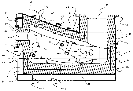
FIG. 1 is a central longitudinal cross-section of the refractory-lined reactor
vessel of
one embodiment of an aspect of the present invention;
FIG. 2 is a side and rear isometric view of the refractory-lined reactor
vessel of
FIG. 1, particularly showing the inlet and outlet ports;
FIG. 3 is a top plan view of the refractory-lined reactor vessel of FIG. 1;
and
FIG. 4 is a side elevational schematic view of one embodiment of an opacity
monitor forming a part of the refractory-line vessel of embodiments of aspects
of the
present invention;
FIG. 5 is a block diagram showing the overall organization of chemical process
simulation according to the present invention;
FIG. 6 is a high-level flow chart showing the chemical process simulator block
in
figure 5 in more detail;
FIG. 7 is a block flow diagram showing the overall organization of the
temperature
and dynamic model simulation according to the present invention; and
FIG. 8 is a high-level flow chart showing the dynamic model simulator block in
figure 7 in more detail.
DESCRIPTION OF PREFERRED EMBODIMENTS
[0075] One embodiment of an aspect of the present invention includes three
plasma
arc generators mounted in a cylindrical, refractory-lined reactor vessel with
sloping top, as
depicted in FIG. 1, FIG. 2 and FIG. 3, and as will be described in detail
hereinafter. As
seen therein, the cylindrical vessel I O comprises a shell 12 in two sections,
upper section
16 and lower section 18, each of which is Iined with a refractory material I4U
in upper
section 16 and 14L in lower section 18. Examples of suitable refractory
materials include
ceramic blanket, insulating firebrick and high alumina hot face brick,
possibly with smaller
amounts of chromium oxide, zirconium oxide or magnesium oxide.
[0076] As previously discussed, the lower section 18 of the vessel 10 is
subject to
more degrading environments and so the refractory material 14L is a much more
robust
CA 02457335 2004-02-10
19
refractory material. Examples of such more robust refractory materials include
DIDIER
DIDOFLO 89CR and RADEX COMPAC-FLO V253.
[0077] 'The vessel 10 is provided with a solid waste and/or hazardous material
inlet
feed port 20, and with two spaced-apart liquid waste and/or hazardous material
feed inlet
ports 22. The vessel 10 is also provided with a refractory-lined gas outlet
conduit 24.
Furthermore, the vessel 10 is provided with a slag pool collection zone 26,
and, leading
therefrom, a slag extraction port 28.
[0078] Further inlet ports include a plurality, in this embodiment, five,
spaced-apart
air inlet ports 30. These air inlet ports 30 are strategically located to
ensure that the input of
the air process additive blankets the entire processing zone for maximum
efficiency. Also,
a plurality, in this embodiment, three, steam injection ports 32 are provided.
These steam
injection ports 32 are strategically located to ensure that the inlet steam
process additive
blankets the processing zone for maximum processing efficiency, and blankets
the product
gas at its exit from the reactor vessel to achieve total conversion of any
remaining un-
reacted carbon with the additional result that the endothermic reaction cools
the product
gas to the desired level just prior to its exit from the reactor vessel. In
addition, a plurality,
in this embodiment, four, CCTV inspection ports 34, are provided. These CCTV
inspection
ports 34 are strategically located to ensure that the operator has complete
and continuous
visibility of all aspects of the processing.
[0079] Two sets of plasma arc generators are provided. The first set is a
fixed set
of, in this embodiment, two, diametrically-opposed, side-mounted, fixed plasma
arc
generators 36 with center line angular displacement so as to point their
plasma arc plumes
to a focal point. The second set is a single top mounted plasma arc generator
38 with three
degrees of freedom of movement, as shown by the arrows.
[0080] The cylindrical vessel 10 is provided with a sloping top 40. This
sloping top
40 is provided to ensure that the top mounted plasma arc generator 38 can
deliver its heat
fully and efficiently to the required areas by means of the plasma arc
generator within the
reactor vessel. As shown, a zone 42 constitutes the extremely high temperature
processing
zone.
CA 02457335 2004-02-10
[0(181 ] Two other desirable features of the reactor vessel 10 include: the
fact that
the lower part 18 of the reactor vessel may be separated from the remainder of
the reactor
vessel 10. This is achieved by means of attachment flanges 44. A preheat
burner port 46 is
provided to enable the zone 42 inside of the reactor vessel to be preheated to
a suitable
initial operating temperature.
[0082] The reactor vessel 10 is supported on rails 48.
[0083] As seen in FIG. 4, the outlet gas emerging from gas outlet conduit 24
is
passed through product gas piping S0, which mounts the opacity monitor 52. The
opacity
monitor 52 includes a transmitter 54 and a receiver 56. Portions of the piping
which houses
the opacity monitor 52 are water-cooled, at 58. At the extreme ends of the
opacity monitor
52, are nitrogen purge elements 60 to direct a flow of nitrogen to keep
airborne part'culates
from depositing on the inside faces of the opacity monitor sensor elements 54
and 56.
[0084] Alternatively, or in conjunction therewith, a slightly negative
pressure zone
64 may be set up in the piping 50 to keep airborne particles from depositing
on the inside
faces of the opacity sensor elements 54 and 56.
OPERATION OF PREFERRED EMBODIMENT
[0085] The operation of the plasma gasification reactor 10 commences with a
fossil
fuel burner being inserted into the preheat burner port 46 in reactor vessel
10. After a
maximum temperature {e.g., 900°C) has been achieved in vessel 10 with
this burner, the
burner is removed, the port 46, which permits entry of the preheat burner, is
sealed and
plasma arc generators 36 and 38 are inserted and turned on to bring the total
reactor vessel
temperature to the desired operation temperature (e.g., 1100°C or
1200°C depending on the
waste stream being processed). At this time, a predetermined flow of process
additive
steam is established through steam ports 32 and a predetermined flow of
process additive
air is established through air ports 30. The predetermined positions of the
steam ports 32
and the air ports 30 are as determined by the temperature and flow dynamic
model (to be
described hereinafter). Thereafter, the predetermined flow of both steam and
air process
additives is as determined by the chemical stimulator (to be described
hereinafter) for the
type of waste and/or hazardous material to be processed. Feeding of waste
and/or
CA 02457335 2004-02-10
21
hazardous material into vessel 10 is then commenced through solid waste port
20 and/or
liquid waste ports 22 depending on the type of waste and/or hazardous material
being
processed. Input waste and/or hazardous material is decomposed within the
extremely high
temperature processing zone 42 to form a molten solid product and a product
gas. The
molten solid product, referred to as slag, flows to the slag pool collection
area 26 where it
resides until it is extracted from vessel 10 through slag extraction port 28.
Slag extraction
through slag extraction port 28 can be continuous when the input waste and/or
hazardous
material contains adequate amounts of slag producing constituents or it can be
intermittent.
The product gas exits vessel 10 through gas outlet conduit 24. The preferred
embodiment
of the refractory lined plasma gasification reactor vessel 10 contains up to
three steam
process additive injection ports 32, up to five air process additive injection
ports 30, and up
to four CCTV inspection ports 34. Other embodiments include those wherein a
different
number of process additive input ports is dictated by the temperature and flow
dynamic
model simulator (to be described hereinafter) in order to maintain the optical
operational
characteristics
j0086] Fixed plasma arc generators 36 provide a consolidated front of an
extremely
high temperature processing zone 42 across the entire periphery of the
refractory lined
reactor vessel I 0 between the input waste ports 20, 22, and the processing by-
product outlet
conduit 24 for the product gas and slag extraction port 28 for the molten
slag. Fixed plasma
arc generators 36 have a combined plasma arc plume focal point to ensure that
the profile
of the high temperature processing zone 42 remains complete and optimal.
Plasma arc
generator 38 has three degrees of freedom to permit it to add high temperature
processing
assistance anywhere it is required within vessel 10, ranging from heat
assistance to the
processing zone profile 42 created by plasma arc generators 36, to ensuring
that the slag in
the slag pool collection area 26 is fully processed and slag exit port 28 is
kept open during
all slag extraction periods.
(0087] The product gas on exit from reactor vessel 10 through outlet conduit
24
proceeds through product gas piping SO and passes through opacity monitor S2.
The
opacity monitor S2 provides a measure of the amount of airborne particulates
in the product
gas by communication between opacity monitor transmitter 54 and opacity
monitor
receiver S6. Sections S8 of the piping which houses the opacity monitor S2
which contact
CA 02457335 2004-02-10
22
the hot product gas piping 50 are cooled, e.g., water cooled to ensure opacity
monitor
transmitter 54 and opacity monitor receiver 56 are not overheated. Nitrogen
purge 60
prevents deposition of any airborne particles from settling on the opacity
monitor
transmitter sensor 54 or on the opacity monitor receiver sensor 56, which
would impede
opacity monitor sensitivity and, hence accuracy. Alternatively, instead of the
nitrogen
purges 60, a slightly negative pressure area 64 can be maintained to prevent
airborne
particles from depositing on either the opacity monitor transmitter sensor 52
or the opacity
monitor receiver sensor 56. The reading from opacity monitor 52 is passed to a
control
console for process control purposes. Process control is effected through
adjustment of
steam flow rate through steam process additive injection ports 32, which, in
turn,
simultaneously affects the air input through air process additive injection
ports 30. Any
changes in steam or air process additive injection into the process also
affect the generated
product gas flow rate.
[0088] The operator of the system maintains full and continuous visibility of
all
aspects of processing within vessel 10 through CCTV inspection ports 34.
(0089) Inspection and repair of the reactor vessel refractory lining 14U and
14L as
required is facilitated by removing lower section 18 of refractory lined
reactor vessel 10 by
means of disconnection of flange 44.
[0090] In order to more effectively assist in final design to ensure optimum
reactor
vessel geometry, the physical characteristics and chemical composition of the
input waste,
and the required throughput of the system are taken into consideration.
[0091 ] Thus, according to aspects of the present invention, processing
control is
exercised through continuous reactor vessel pressure and temperature
monitoring plus
continuous product gas flow rate and opacity monitoring.
(0092] A detailed assessment of the required processing characteristics for
most
optimum destruction of the waste and/or hazardous material stream being
processed
includes the following, the detailed assessment of which is provided by the
proprietary
chemical simulator:
optimal operating characteristics including processing temperature required;
CA 02457335 2004-02-10
23
product gas quantity and quality characteristics including the amount of
energy which may be recoverable from it;
the chemical composition of elements which make up the product gas;
the quantity ofprocess additives required, e.g., steam, for most complete
conversion of carbon to a carbon monoxide fuel gas;
the amount of moisture in the product gas;
throughput achievable with the particular waste stream under consideration;
total system design characteristics including optimum design for lowest cost;
and
by-products recoverable.
[0(193] FIG. S is an explicatory flow diagram of the chemical process
simulator
showing its functionality with variable waste characterization inputs,
operator interactive
inputs for optimization and system output characterizations. Input and/or
process
characteristics can be varied at will within the chemical process simulator to
visualize
processing impacts in order to arrive at the most efficient and effective
disposal process for
the particular waste stream under consideration. The chemical process
simulator also serves
as a continuous monitoring tool to determine operational characteristics
changes which
may be required by virtue of changes in the chemical composition of the input
waste and/or
hazardous material stream.
[0094] FIG 6 is a high-level flow chart of the chemical process simulator of
figure
showing its computational aspects. In general, the simulator consists of three
main
computational blocks:
(i) An Ideal Reaction Model which calculates the ideal, steady state
equilibrium composition of the product gas, by minimizing the Gibbs free
energy of the
product chemical species in adiabatic, isobaric equilibrium.
The principle of obtaining equilibrium reaction products for simple chemical
systems by
Gibbs free energy minimization is well established and is often taught in
introductory
chemistry courses. In the late 1960's, researchers at NASA developed a general
Gibbs
minimization approach applicable to finding the equilibrium composition of
arbitrarily
CA 02457335 2004-02-10
24
large systems without the need to write equilibrium reactions is explained in
a publication
by Gordon, S., and B.J. McBride: Computer Program for the Calculation of
Complex
Chemical Equilibrium Compositions with Applications; I. Analysis. NASA
Reference
Publication 1311 ( 1994). This publication is incorporated herein by
reference. The ideal
reaction model operates using this approach, which a solution matrix is
populated with the
elemental composition of each reaction product under consideration, along with
each
product's Gibbs Free Energy at the current reaction temperature. The matrix is
then solved
for the minimum total Gibbs free energy, (while simultaneously adhering to the
principle of
conservation of mass by balancing the elemental inputs and outputs) by
Gaussian
elimination.
(ii) A Carbon Deposition Model, which calculates the amount of soot (solid
Carbon C(s)) formed, or the amount of steam needed to eliminate soot formation
by
comparing the input composition vs. equilibrium curves.
As implemented, the ideal reaction model can only solve gas-phase equilibriae.
Consequently, since solid carbon has been observed to form during operation of
a plasma
gasification process, a separate model was developed to calculate C(s)
formation rates.
Curves that predict the amount of C(s) subliming from a three phase gaseous
system were
obtained from the book by Kyle, B. G., Chemical and Process Thermodynamics,
2°d ed.,
Prentice Hall, New Jersey, 1992, which is incorporated herein by reference.
These curves
were converted into a numerical fimction that predicts the amount of solid
carbon that will
form at a given Temperature, molar % of Hydrogen, and molar % of oxygen in the
system.
Using this function, the software calculates the amount of C(s) that is formed
- this amount
is sent directly to the recombination section of the code, and is subtracted
from the
elemental composition of the reactants. This revised elemental composition is
used in the
subsequent non-ideal reaction model.
As a user-selectable option, this model is also used to recursively solve for
the amount of
water that must be added to the system in order to eliminate the formation of
solid Carbon.
Water is used for this application, because it contains both Hydrogen and
Oxygen.
Increasing either relative to the amount of Carbon in the system decreases the
formation of
C(s). Consequently, moisture is extremely effective in limiting the amount of
C(s) formed,
CA 02457335 2004-02-10
since it decreases the amount of Carbon in the system relative to both Oxygen
and
Hydrogen.
When this option is selected, the amount of C(s) formed is always zero, so it
has no effect
on the subsequent elemental composition. However, because additional water is
added to
the reaction, Hydrogen and Oxygen are added to the net elemental composition
in
accordance to the amount of water calculated in this step. The amount of water
so
calculated is also retained in memory, so that it can be outputted with the
rest of the results
once calculations have been completed.
(iii) A Non-ideal Reaction Model which determines the amount of methane,
acetylene and ethylene that is formed in excess of the ideal as calculated by
multiplying the
amount of Carbon in the system by experimentally derived ratios. This
approximates the
result of non-total decomposition of long-chain hydrocarbons or polymers. In
practice,
such molecules decompose into small hydrocarbons (typically I or Z Carbon
hydrocarbons)
before these in turn react with other chemical species. Because of the highly
turbulent
nature of the gaseous environment within a plasma gasification reactor, a
small fraction of
these hydrocarbons are carried out of the principal reaction areas before they
are consumed.
The specific ratios chosen for a given waste vary depending on the proximate
physical
composition of the material.
(0095] The products of non-ideal reactions are subtracted from the elemental
composition available for ideal reactions. These products are passed to the
recombination
stage of the software, whereas the balance of the elemental composition is
passed to the
ideal reaction model. Thus, the software computes the total inputs on an
elemental basis;
splits the input between the three computational models; combines the results
from the
three computational models; tabulates the results; and stores the results in a
database.
[0096] Refernng to the individual blocks within FIG 6:
[0097] Input Parameters 101: Includes the waste composition (elemental molar
%,
moisture content and heating value) and flow rate, the processing temperature
and additives
including the capability to specify air from several avenues, oxygen, water,
steam and the
range of iteration of any of the process inputs;
[0098] Decomposition Constituents 102: Each input to the plasma gasification
reactor is converted into elemental molar flows. The total molar flow of each
element is
CA 02457335 2004-02-10
26
used as the primary variable for the three principle calculation routines
described
previously;
[0099] C-Deposition Model 103: The ideal reaction model can only solve gas-
phase reactions. A separate computational block is therefore implemented (as
described
above) to determine the formation rate of solid Carbon C(s). The mathematical
function
designed to perform this calculation can alternatively be used in a recursive
loop to
determine the amount of water needed to prevent formation of solid Carbon;
[00100] Non-Ideal Reaction Model 104: Calculates the compounds formed by
incomplete reactions. Simple hydrocarbons are formed proportionate to the
amount of
Carbon in the system, in tandem with user-defined ratios. These ratios are
selected based
on the proximate composition of the waste, and the current operating
conditions. Normal
kinetic models are insuft:icient in this application because the original
waste stream can
rarely be analyzed sufficiently to allow their use. Consequently, values
derived
experimentally with similar materials are used in this model. Elements used in
these
reactions are subtracted from the elemental composition available for the
ideal reactions
stage. The compounds formed in this stage are passed to the recombination
stage, where
they are agglomerated with the remainder of the results;
[00101 ] Ideal Reaction Model 1 O5: Calculates the compounds formed under
ideal,
steady-state conditions;
(00102] Results Combiner 106: Combines the results from the C-Deposition Model
103, the Non-Ideal Reaction Model 104 and the Ideal Reaction Model 105; and
[00103] Tabulator & Formatter 107: Tabulates all calculated data in a format
convenient for export to most other software. In practice, data is exported to
a Microsoft
Excel worksheet, where the mass of each product, volume %, sensible heats, gas
heating
value, electricity heat input requirement and the selection of the plasma
gasification
process optimal operating point based on specific energy and environmental
considerations
are determined. The optimal operating point is the minimum processing energy
required to
meet environmental emission requirements.
CA 02457335 2004-02-10
27
[00104] Through the development of the chemical process simulator, the first
step
was the development of a process model along with the implementation of the
software and
the thermo-chemical database using the principle of minimization of Gibb's
free energy to
allow prediction of the product gas components at a specific temperature and
specific set of
input parameters. A C-H-O system was implemented to determine the areas of
carbon
deposition. A calculation method for the energy balance was developed for the
plasma
gasification process to determine the power requirement of the plasma arc
generator for
gasification of municipal solid waste. It was then extrapolated to include
other
carbonaceous materials.
[00105] For pure substances, elemental composition, and thermodynamic
properties
are readily available. However, most waste materials are inhomogeneous,
complex in
structure and often have unknown chemical formulae. In these cases the molar
composition of the waste is determined from its mass composition which is
readily
obtained by laboratory analysis. Similarly, the standard heat of formation of
the waste
material must also be known. Typically, this is determined in the laboratory
by bomb
calorimetry, although for more homogeneous material, it is often possible to
find these
values from literature.
[00106] The plasma arc generator power requirement is calculated based on
plasma
reactor vessel inputs and outputs, and plasma gasification conditions. Energy
in to the
plasma reactor vessel is the sum of the energy supplied by the plasma arc
generator and the
total enthalpy of the input waste into the plasma reactor vessel. Energy out
is the sum of the
total enthalpy of output elements from the plasma reactor vessel and the heat
loss through
the plasma reactor vessel walls. The total power required from the plasma arc
generator is
the dii~erence of the two, accounting for efficiency of the plasma arc
generator itself.
[00107) The chemical process simulator provides performance data on the plasma
gasification of wastes since its development integrated the existing extensive
practical
database results. The complete simulator is in two discrete modules, the
mass/elemental
balance of the system is derived using the previously described software,
whereas results
tabulated, and the energy balance of the system is derived using an Excel(TM)
worksheet.
The results worksheet is maintained as a separate module for three main
reasons:
CA 02457335 2004-02-10
28
(a) Facilitating reduced development time;
(b) Facilitating the ability to rapidly make changes to the thermodynamic
model
without the need for substantial alteration of the software; and
(c) Facilitating data portability into documents/spreadsheets/presentations as
supported by Excel, eliminating the need for coding these capabilities into
the
simulator itself.
[00108] This Excel worksheet calculates thermodynamic properties of the
relevant
compounds using Shomate equations. Constants for these equations were obtained
from
the NASA thermodynamic database associated with the ideal reaction method
described
previously, as provided in the publication by Bonnie J. McBride and Sanford
Cordon,
Computer Program for Calculation of Complex Chemical Equilibrium Compositions
and
Applications: II. Users Manual and Program Description, NASA Reference
Publication
131 l, June 1996; which is incorporated herein by reference. These
thermodynamic
properties are used, together with standard thermodynamic calculations to
determine the
overall energy balance of the gasification reaction, and by inference, the net
supplemental
heat required to drive the process.
[00109] Recognizing that the reactor vessel is not at a uniform temperature,
the
simulator calculates gas composition and flow rates across a range of several
different
temperatures. A gas composition is then interpolated on the spreadsheet for
the desired
vessel temperature, by giving each ofthe different simulated temperature
scenarios a
weight according to a Poisson probability with a mean value equal to the
average reactor
vessel temperature. The sum of the weight-reduced scenarios is then
normalized, providing
the "average" result. It is this "average" result that is, in turn, used to
calculate the energy
balance of the system.
[00110] A further refinement is that the CHO boundary system is now
mathematically modelled within the simulator. Thus, the simulator can now
automatically
calculate the amount of C(s) generated for a given scenario. Because C(s)
formation is
detrimental to the cleanliness of the product gas, a routine was developed to
automatically
adjust the steam injection rate to the minimum level required to completely
eliminate the
formation of this carbon. It has been found that this approach gives gas
compositions
CA 02457335 2004-02-10
29
closer to experimental data than a strict one-temperature model. The following
table shows
a comparison of the results for municipal solid waste:
Comparison of Simulated and Experimental Results for MSW
Gibbs Actual
Modified Minimization Test
Simulator Model Data
Product Gas Scrubber Scrubber Scrubber
Composition Vessel Exit Vessel Exit Exit
Exit Exit
C 1.580 -
kg
CH4 2.12% 2.35% 30 ppm 34 ppm 2.76%
CZHZ 0. I I 0.12% 0.14%
%
C2H4 0.17% 0.18% 0.22%
CO 22.46% 24.91 25.04% 28.95% 29.19%
%
COZ 6.41% 7.11% 6.23% 7.21% 8.33%
COS 21 ppm 21 ppm
HZ 36.43% 40.40% 36.76% 42.49% 37.74%
HCl 947 ppm 934 ppm -
H20 9.64% 13.30%
HS 3 ppm
HZS 971 ppm 959 ppm
NZ 19.08J 21.16% 18.47% 21.35% 21.22%
NHj 29 ppm 18 ppm -
OZ 3.39% 3.76% - 0.40%
(00111 ~ In order to develop a more reliable and detailed estimate of
operating costs,
the chemical process simulator also calculates power consumption for the
parasitic loads
associated with a plasma gasification system, as well as the electrical power
generated by a
steam turbine, combined cycle gas turbine and a gas engine facility.
Performance data for
CA 02457335 2004-02-10
individual equipment is, by default, scaled from a baseline facility design.
However, since
the calculations are performed on a spreadsheet, equipment performance can
quickly be
adjusted to reflect different configurations.
[00112 ] As a result of the enhanced capability of the chemical process
simulator to
generate data for ranges of input conditions and flows, it is possible to
quickly generate an
optimised scenario by varying steam & air flows across a user-selected range,
then
choosing the scenario with the preferred gas composition and power
characteristics. This
code was designed with versatility in mind. It gives exactly what is required
by RCL
designers (and strictly no more than that so the speed is not jeopardised).
PLUS, it allows
very fast iterations for selection of RCL's definition of "optimal" operating
point. This is
where our code and established platforms such as ASPEN and HYSYS differ.
[00113] Because of the efficiencies associated with the use and generation of
electricity, for combustible wastes it will inevitably be more energy
efficient to increase the
amount of air allowed into the reactor vessel. Addition of sufficient amounts
of air will
usually reduce the supplemental plasma heat required to maintain the reaction
at steady
state to or below zero. Reduction of the plasma heat below zero (which for
these purposes
means that the reactor temperature is increasing) is usually accomplished by
increasing the
air flow to near stoichiometric rates for combustion. The inherent cleanliness
and
enhanced process control associated with pyrolysislgasification reactions
generally dictate
the selection of operating parameters that do not permit such an excess of
air, but require
the addition of supplemental heat.
[00114] Thus, for the purposes of designing a baseline gasification system for
a
given waste, a methodology was developed for the selection of a minimum power
requirement for a given waste input. Optimization of the process is carried
out with
regards to air emissions, energy efficiency, capital costs, and operating
costs. Since the
largest variable in capital costs is the size of the plasma torch and power
supply, and
operating costs are also linked directly to torch power, energy efficiency and
air emissions
become the main optimization criteria. Pollutant formation is affected by
operating
temperature, and input composition. Since the waste stream is not variable,
the input
composition is changed only by variations in air and steam inputs. Power
consumption is
similarly affected by these parameters.
CA 02457335 2004-02-10
31
[00115) Consequently, in order to optimize a scenario, the operating
temperature is
selected with regards to minimization of pollutants, and air and steam flows
are varied to
reduce the operating power to the minimum power scenario. It was found that
while the
addition of steam will reduce the operating power, the effect is not as
significant as the
addition of a comparable mass of air. Steam addition, however, results in an
improved
product gas heating value.
[00116] The chemical process simulator models the effects of non-ideal
reactions
due to incomplete reactions and reaction kinetics. These account for the
observed
deviations in experimental product gas chemistry. It also includes a model for
the
formation of soot (carbon black), which is a precursor to dioxin formation. In
addition to
minimizing dioxin formation, avoiding the carbon-forming regime also
significantly
reduces the formation of tars and other polyaromatic hydrocarbons, which is
normally a
serious complication of typical gasification processes.
[00117] The chemical process simulator allows for rapid generation and
exploration
of different operating scenarios. Consequently, the most economic operating
scenario in
which there are no technical hurdles encountered can be quickly determined.
The chemical
process simulator is also used to develop process control logic for extremely
non-
homogeneous waste (e.g. mufti-waste streams). Because a number of "what if'
scenarios
have been developed ahead of time using process simulation, the control system
can
extrapolate the current waste composition from the tail-gas composition, and
adjust the
process chemistry to an "ideal" operating point. Again, the versatility of the
RCL code and
the relative ease and speed of data acquisition and manipulation makes this
possible.
0118] The temperature and flow dynamic model simulator provides isometric
printouts of temperature distribution and gas flow characteristics throughout
any cross
section of the reactor vessel. These features provide an essential tool for
optimization of the
reactor vessel design to ensure there are no gas paths within the reactor
vessel which would
permit gaseous elements to exit the vessel without being subjected to the fill
required
processing temperature and residence time as well as to confirm that
refractory erosion, hot
spots and cold spots are avoided. The printout from this simulator dictates
the optimum
physical positioning of input additive ports and monitors the overall impact
of the input
process additives flow as identified by the chemical simulator. The influence
of physical
CA 02457335 2004-02-10
32
position changes of these ports coupled with the processing additive flow
rates can be
assessed very readily and the most optimum positions can be determined.
(00119] FIG. 7 is an explicatory flow diagram of the temperature and flow
dynamic
model simulator showing its functionality with variable waste characterization
inputs,
operator interactive inputs for optimization and system output design
characterizations.
[00120] FIG 8 is a high level flow chart of the temperature and flow dynamic
model
simulator showing its computational aspects. With reference to FIG 8, the
function of each
block in the flow chart is as follows:
[00121 ] Vessel Geometry I 1 I : Input of the geometrical dimensions of the
plasma
gasification reactor vessel to create the computational domain on which the
numerical
results of the mathematical model are calculated;
[00122] Run Gambit 112: Before running Fluent, it is necessary to run Gambit
to set
up the solution domain and to generate the computational meshes. Meshes can be
selected
on virtually any plane through the periphery of the reactor vessel and the
fineness of the
mesh can be selected depending on the geometrical dimensions and the
operational needs
of the results printout;
[00123] Initial Condition 113: The assumed initial condition includes all the
quantities, such as velocity, temperature, etc., to be calculated. The initial
values of these
quantities are required in order to initiate the iteration process;
[00124] Boundary Conditions 114: Input data defining conditions of operation,
including the flow rate, composition and temperature from the plasma arc
generators, the
air jets, the steam jets, are required by the CFD code (Fluent) to define the
adequate
boundary conditions which simulate the operation condition of the plasma
gasification
reactor vessel as close as possible;
[00125) Input 115 (the number of species and reactions to be included in the
simulation): This is to control the level of sophistication to model the
chemical reactions.
The inclusion of major species is important to get the temperature and density
correct.
Inclusion of minor species is essential to predict pollutant emissions;
CA 02457335 2004-02-10
33
[00126] Model Selection 116 (user selection of models to simulate turbulence
and
turbulent combustion): Fluent offers various mathematical models to simulate
turbulence
and turbulent combustion.
[00127] Fluent Code Execution I 17: Once the computational meshes are
generated
and the boundary and initial conditions are defined, the Fluent code is
executed until a pre-
defined convergence criterion is satisfied. The code is essentially a non-
linear solver of
system of equations describing the convergence of mass, momentum, energy, and
species;
and
[00128] Results Post-Processing 118: Generates graphic plots to display the
numerical results for analysis and visualization. Generated data is stored as
normal data
files.
[00129] The computational fluid dynamic (CFD) approach, which is the basis of
Fluent, is a very useful tool in the evaluation and improvement of new plasma
gasification
reactor vessel designs. CFD permits innovative computer modelling and
numerical analysis
techniques in the areas of flow, heat transfer, and combusting flows. These
techniques are a
powerful tool to improve the design and operation of various industrial
systems. Turbulent
mixing and heat transfer in the plasma gasification reactor vessel are
numerically simulated
in order to evaluate operational performance of the reactor vessel. Inlet
conditions
including velocity and enthalpy of the plasma arc generators, air and steam
jets are
specified as inputs. Adiabatic heat transfer conditions are assumed at the
reactor vessel
walls. Continuous feed of solid waste is simulated by a low-temperature and
low-velocity
gas stream flowing into the reactor vessel. The solid waste removal region is
simulated
with a fixed temperature zone at the desired level. Zero-gradient is assumed
for all
variables at the reactor vessel exit.
[00130) The energy conservation equation is solved simultaneously with the
momentum and turbulence equations. Every effort is made to simulate both the
velocity
and the temperature profiles as close to reality as possible. The results
obtained provide
qualitative to semi-quantitative information on both flow and temperature
fields in the
reactor vessel. These velocity and temperature distributions provide direction
to improve
the design and operation of the plasma gasification reactor.
CA 02457335 2004-02-10
34
(00131 ( Flow modeling of the reactor vessel is performed to ensure proper
mixing of
process inputs, and to ensure that kinetic effects are not significant. In the
normal design
process, results from flow modeling are used recessively to fine-tune the
kinetic effects in
the chemical simulation, as well as to adjust the reaction temperature profile
within the
simulator. Flow modeling results are also used to assist refractory design
since all
operating.characteristics at the refractory surface can readily be identified.
[00132] Velocity and temperature mesh profile printouts are scrutinized for
acceptability of operations for the specified waste stream. Any less than
optimal aspects
can be addressed through a number of operational and/or dimensional design
changes such
as:
(a) The physical shape and/or size of the reactor vessel;
(b) 'The physical location(s), orientation and/or power levels) of the plasma
arc
generator(s);
(c) The physical locations) and/or orientation of the various process additive
ports;
(d) The dimensions of the process additive ports to effect changes in process
additive inlet velocity; or
(e) The input levels) of the various process additive agents.
(00133] The simulator can then be rerun and the new results assessed for
operational
improvements. Such iterations can be repeated any number of times until an
optimal
scenario of operations is found for the waste stream being considered. The
benefit of such a
procedure is self evident since the optimal operating scenario can be
identified very rapidly
and then the operating system can be commenced with the maximum probability of
success.
[00134] Input and/or process characteristics can be varied at will within the
chemical
simulator to visualize processing impacts in order to arrive at the most
e~cient and
effective disposal process for the particular waste stream under
consideration. The
chemical simulator also serves as a continuous monitoring tool to determine
operational
characteristics changes which may be required by virtue of changes in the
chemical
composition of the input waste and/or hazardous material stream.
CA 02457335 2004-02-10
[00135] The temperature and flow dynamic model simulator provides isometric
printouts of temperature distribution and gas flow characteristics throughout
any cross
section of the reactor vessel. These features provide an essential tool for
optimization of the
reactor vessel design to ensure there are no gas paths within the reactor
vessel which would
permit gaseous elements to exit the vessel without being subjected to the full
required
processing temperature and residence time as well as to confirm that
refractory erosion, hot
spots and cold spots are avoided. 'The printout from this simulator dictates
the optimum
physical positioning of input additive ports and monitors the overall impact
of the input
process additives flow as identified by the chemical simulator. The influence
of physical
position changes of these ports coupled with the processing additive flow
rates can be
assessed very readily and the most optimum positions can be determined.
[00136) While the invention has been so shown, described and illustrated, it
should
be understood by those skilled in the art that equivalent changes in form and
detail may be
made therein. One such change in form is that for ease of fabrication, the
described
cylindrical reactor vessel can be mufti-sided with low profile sides and
corresponding
mufti-sloping top sections converging to the gas exit port and with the plasma
arc
generators being inserted into the vessel through the top sloping sections. In
a further
embodiment of this mufti-sided reactor vessel, the corresponding mufti-sloping
top section
may converge to the gas exit in the center profile of the reactor vessel.
[00137] From the foregoing description, one skilled in the art can easily
ascertain the
essential characteristics of this invention, and without departing from the
spirit and scope
thereof, can make various changes and modifications of the invention to adapt
it to various
usages and conditions. Consequently, such changes and modifications are
properly,
equitably, and "intended" to be, within the full range of equivalence of the
following
claims.