Language selection

Search

Patent 2457661 Summary

Third-party information liability

Some of the information on this Web page has been provided by external sources. The Government of Canada is not responsible for the accuracy, reliability or currency of the information supplied by external sources. Users wishing to rely upon this information should consult directly with the source of the information. Content provided by external sources is not subject to official languages, privacy and accessibility requirements.

Claims and Abstract availability

Any discrepancies in the text and image of the Claims and Abstract are due to differing posting times. Text of the Claims and Abstract are posted:

  • At the time the application is open to public inspection;
  • At the time of issue of the patent (grant).
(12) Patent: (11) CA 2457661
(54) English Title: MULTI-CELL TANK FOR PRESSURISED GAS
(54) French Title: RESERVOIR A CELLULES MULTIPLES POUR GAZ SOUS PRESSION
Status: Expired and beyond the Period of Reversal
Bibliographic Data
(51) International Patent Classification (IPC):
  • F17C 13/08 (2006.01)
  • F17C 1/02 (2006.01)
(72) Inventors :
  • LUONGO, NICOLANTONIO (Italy)
(73) Owners :
  • SIDA ENGINEERING-S.R.L.
(71) Applicants :
  • SIDA ENGINEERING-S.R.L. (Italy)
(74) Agent: GOWLING WLG (CANADA) LLP
(74) Associate agent:
(45) Issued: 2010-12-07
(86) PCT Filing Date: 2002-08-07
(87) Open to Public Inspection: 2003-02-27
Examination requested: 2007-08-03
Availability of licence: N/A
Dedicated to the Public: N/A
(25) Language of filing: English

Patent Cooperation Treaty (PCT): Yes
(86) PCT Filing Number: PCT/IT2002/000526
(87) International Publication Number: WO 2003016777
(85) National Entry: 2004-02-13

(30) Application Priority Data:
Application No. Country/Territory Date
MC2001A000086 (Italy) 2001-08-20

Abstracts

English Abstract


The present invention relates to a multi-cell tank (2) for pressurised gas
formed by a group of tubes (2a) immersed in a fibrous resin body (4) and
reinforced by means of external texture (7), closed with two covers that
feature a intercommunicating series of domes on the internal side, which
exactly match the opening of the tubes of the group.


French Abstract

L'invention concerne un réservoir à cellules multiples (2) pour gaz sous pression, qui consiste en un groupe de tubes (2a) immergés dans un corps (4) de résine fibreuse et renforcés par une texture externe (7). Ces tubes sont fermés à l'aide de deux couvercles formant une série de dômes communiquants sur leur face interne, qui s'assemblent exactement avec l'ouverture des tubes.

Claims

Note: Claims are shown in the official language in which they were submitted.

-5-
What is claimed is:
1. A multi-cell tank for pressurised gas, the multi-cell tank comprising:
- a group of tubes supported by spacing plates with a parallel close series of
holes suitable for housing similar tubes that are placed in such a way that
each tube is almost in contact with the adjacent tubes;
- a body of fibrous resin that fills all the spaces in the group of tubes,
including
perimeter spaces, where the resin is perfectly flush with the borders of the
spacing plates;
- two covers that close the two ends of the group of tubes and feature a
series
of hemispherical domes on the internal side, which communicate through
ducts and exactly match the opening of the tubes in the group;
- tie rods that join the two covers to the group of tubes and pass through the
spaces in the group of tubes and through holes suitably provided on the
spacing plates;
- an external reinforced layer realised by wrapping the group of tubes in a
first
texture with resin-bonded continuous wire or wires, on which a second texture
with resin-bonded wires in longitudinal directions only is laid in order to
join the
covers applied and tightened with tie rods to the group of tubes;
- a pre-formed external protection enclosure, preferably with aluminum sheet;
- an ordinary gas valve applied on a hole located on one of the two bottom
covers.

Description

Note: Descriptions are shown in the official language in which they were submitted.


CA 02457661 2004-02-13
WO 03/016777 PCT/IT02/00526
Description
Multi-cell tank for pressurised 4as
The present patent application for industrial invention relates to a multi-
cell tank for pressurised gas with modular structure that allows it to be
realised with variable volume and capacity according to the use and
installation place of the tank.
Although the main use for this tank is in natural gas vehicles, it is
understood that the tank can be used to store any type of high-pressure
technical gas.
The tank of the invention is an alternative solution to traditional steel
cylinders, with several advantages, such as higher operating safety, easier
internal inspection during re-testing, lower weight, higher flexibility in
terms of
shapes and volumes at the same capacity.
The characteristics of the tank of the invention result from its basic
constructive configuration, according to which the total capacity of the tank
is
given by multiple cylindrical cells in parallel intercommunicating position,
realised with a group of thin tubes, to which mechanical resistance is given
through an external reinforcement coating of composite resins.
More precisely, the tank of the invention comprises a group of tubes
supported by spacing plates with a parallel close series of holes suitable for
housing similar tubes that are placed in such a way that each tube is almost
in contact with the adjacent tubes in order to reduce dimensions.
The group of tubes is immersed in fibrous resin that fills all the spaces
in the group of tubes, flush with the borders of the spacing plates.
The two ends of the group of tubes are sealed with two closing covers
that feature an intercommunicating series of hemispherical domes on the
internal side, which exactly match the opening of the tubes in the group.
The two covers are joined to the group of tubes by means of tie rods
passing through the spaces in the group of tubes.
The group of tubes immersed in fibrous resin is reinforced by wrapping

CA 02457661 2004-02-13
WO 03/016777 PCT/IT02/00526
-2
it in a resin-bonded texture with continuous wire, on which a second texture
with resin-bonded longitudinal wires is laid in order to join the two covers.
Finally, the tank of the invention is housed in a suitable pre-formed
protection enclosure, preferably with aluminium sheet.
Based on this general description of the structural configuration of the
tank, the advantages of the tank of the invention become evident with respect
to traditional steel cylinders.
First of all, the tank of the invention can be given different shapes by
selecting the appropriate number of tubes for each perimeter side.
The length of the tank can be changed by simply varying the length of
the tubes in the group.
Moreover, the tank of the invention is characterised by a high
capacity/weight ratio, thanks to the low specific weight of the materials
used,
that is thin metal tubes and fibrous resins, characterised by low specific
weight and high mechanical resistance to tensile stress.
As regards the low thickness of the metal tubes, it must be noted that
the tubes are not required to have good mechanical resistance, in view of the
external fibrous resin coating which is reinforced with transversal and
longitudinal texture.
In other words, the tubes only have a modelling function for the series
of cylindrical cavities to be obtained in the fibrous resin body of the tank.
The higher operating safety of the tank of the invention derives from
the fact that the resistant surtace containing pressurised gas has been
increased with respect to cylinders with the same capacity, thus reducing the
mechanical stress suffered by the surfaces.
As regards the easier internal inspection of the tank, it must be noted
that the group of tubes can be internally inspected and cleaned at any time,
after removing the two covers. Once inspection and maintenance operations
are completed, the two covers are positioned and the tank can be tested.
Currently, for internal inspection purposes, the internal cavity of
cylinders is visually inspected through the hole where the gas delivery valve
is
inserted, after disassembling it. This means that the inspection is carried
out

CA 02457661 2004-02-13
WO 03/016777 PCT/IT02/00526
-3-
through a small hole with $/ inch diameter, which is not sufficient to ensure
total reliability of the control operation aimed to check the integrity of the
internal walls of the cylinder.
For major clarity the description of the tank according to the present
invention continues with reference to the enclosed drawings, which are
intended for purposes of illustration and not in a limiting sense, whereby:
- fig. 1 is a view of the tank with right parallelepiped shape and rectangular
base;
- fig. 2 is a view of the support spacing plate of the group of tubes;
- fig. 3 is a view of the group of tubes supported by spacing plates;
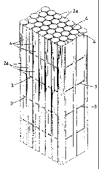
- fig. 4 is a view of the group of tubes immersed in fibrous resin;
- fig. 5 is a view of the group of tubes immersed in fibrous resin and
reinforced
with external texture;
- fig. 6 is a view of the tank provided with covers, not yet inserted in the
protection enclosure, as shown in fig. 1;
- figs. 7 and 8 are cross-sections of fig. 6 with planes VII-VI I and VII I-
VII I;
- fig. 9 is a view of the tank with a different shape.
With reference to the enclosed figures, the tank (1 ) of the invention
comprises a group of thin tubes (2) supported by spacing plates (3) with a
parallel close series of holes (3a) suitable for housing similar tubes (2a)
that
are placed in such a way that each tube (2a) is almost in contact with the
adjacent tubes in order to reduce dimensions, as shown in Fig. 3.
The group of tubes (2) is immersed in fibrous resin (4) that fills all the
spaces in the group of tubes, including perimeter spaces, where the resin is
perfectly flush with the borders of the spacing plates (3), as shown in Fig.
4.
The two ends of the group of tubes (2) are sealed with two closing
covers (5) that feature a series of hemispherical domes (5a) on the internal
side, which communicate through ducts (5b) and exactly match the opening
of the tubes (2a) in the group, as shown in the enlarged view of Fig. 7A.
The two covers (5) are joined to the group of tubes (2) by means of tie
rods (6) passing through the spaces in the group of tubes and through holes
(3b) suitably provided on the spacing plates (3).

CA 02457661 2004-02-13
WO 03/016777 PCT/IT02/00526
-4-
The group of tubes immersed in fibrous resin (4) is reinforced by
wrapping it in a resin-bonded texture with continuos wire (7), as shown in
Fig.
5.
A second texture (7a) with longitudinal direction only is laid over the
first texture (7) in order to join the bottom covers applied and tightened
with
tie rods (6) to the group of tubes (2), as shown in Fig. 6.
The tank of the invention is housed in a suitable pre-formed protection
enclosure (8), preferably with aluminium sheet, as shown in Fig. 1.
One of the bottom covers (5) is provided with a hole for the gas valve,
of conventional type and for this reason not shown on the enclosed drawings.
It must be said that the gas valve can be placed in the most convenient
position in the cover (5), since all hemispherical domes (5) intercommunicate
through ducts (5b) and therefore the gas contained in the tubes (2a) can
reach the valve through the net of intercommunicating domes (5a).
Fig. 9 has been enclosed with the only purpose to show the possibility
of realising the tank of the invention with any shape, including an irregular
shape, according to the space where the tank is installed.
This characteristic of the tank of the invention is extremely helpful and
useful in case of natural gas tanks installed in vehicle trunks. The cylinders
that are currently used for this application have low capacity since they
cannot use the available space at best, being impossible to realise cylinders
with suitable shape and dimensions according to the space in the trunk where
the tank is usually installed.

Representative Drawing
A single figure which represents the drawing illustrating the invention.
Administrative Status

2024-08-01:As part of the Next Generation Patents (NGP) transition, the Canadian Patents Database (CPD) now contains a more detailed Event History, which replicates the Event Log of our new back-office solution.

Please note that "Inactive:" events refers to events no longer in use in our new back-office solution.

For a clearer understanding of the status of the application/patent presented on this page, the site Disclaimer , as well as the definitions for Patent , Event History , Maintenance Fee  and Payment History  should be consulted.

Event History

Description Date
Time Limit for Reversal Expired 2013-08-07
Letter Sent 2012-08-07
Grant by Issuance 2010-12-07
Inactive: Cover page published 2010-12-06
Inactive: Final fee received 2010-09-20
Pre-grant 2010-09-20
Notice of Allowance is Issued 2010-04-26
Letter Sent 2010-04-26
Notice of Allowance is Issued 2010-04-26
Inactive: Approved for allowance (AFA) 2010-04-12
Amendment Received - Voluntary Amendment 2009-11-02
Inactive: S.30(2) Rules - Examiner requisition 2009-07-30
Letter Sent 2007-09-12
Request for Examination Requirements Determined Compliant 2007-08-03
All Requirements for Examination Determined Compliant 2007-08-03
Request for Examination Received 2007-08-03
Letter Sent 2004-05-21
Inactive: Single transfer 2004-04-26
Inactive: Courtesy letter - Evidence 2004-04-06
Inactive: Cover page published 2004-04-05
Inactive: Notice - National entry - No RFE 2004-04-01
Application Received - PCT 2004-03-17
National Entry Requirements Determined Compliant 2004-02-13
Application Published (Open to Public Inspection) 2003-02-27

Abandonment History

There is no abandonment history.

Maintenance Fee

The last payment was received on 2010-08-09

Note : If the full payment has not been received on or before the date indicated, a further fee may be required which may be one of the following

  • the reinstatement fee;
  • the late payment fee; or
  • additional fee to reverse deemed expiry.

Please refer to the CIPO Patent Fees web page to see all current fee amounts.

Owners on Record

Note: Records showing the ownership history in alphabetical order.

Current Owners on Record
SIDA ENGINEERING-S.R.L.
Past Owners on Record
NICOLANTONIO LUONGO
Past Owners that do not appear in the "Owners on Record" listing will appear in other documentation within the application.
Documents

To view selected files, please enter reCAPTCHA code :


To view images, click a link in the Document Description column. To download the documents, select one or more checkboxes in the first column and then click the "Download Selected in PDF format (Zip Archive)" or the "Download Selected as Single PDF" button.

List of published and non-published patent-specific documents on the CPD .

If you have any difficulty accessing content, you can call the Client Service Centre at 1-866-997-1936 or send them an e-mail at CIPO Client Service Centre.


Document
Description 
Date
(yyyy-mm-dd) 
Number of pages   Size of Image (KB) 
Description 2004-02-13 4 184
Drawings 2004-02-13 4 177
Representative drawing 2004-02-13 1 34
Claims 2004-02-13 1 33
Abstract 2004-02-13 2 92
Cover Page 2004-04-05 1 53
Claims 2009-11-02 1 32
Representative drawing 2010-11-19 1 26
Cover Page 2010-11-19 1 53
Reminder of maintenance fee due 2004-04-08 1 109
Notice of National Entry 2004-04-01 1 192
Courtesy - Certificate of registration (related document(s)) 2004-05-21 1 106
Reminder - Request for Examination 2007-04-11 1 115
Acknowledgement of Request for Examination 2007-09-12 1 189
Commissioner's Notice - Application Found Allowable 2010-04-26 1 164
Maintenance Fee Notice 2012-09-18 1 170
PCT 2004-02-13 4 138
Correspondence 2004-04-01 1 26
Fees 2004-08-09 1 34
Fees 2005-08-08 1 27
Fees 2006-08-03 1 39
Fees 2007-08-02 1 39
Fees 2008-07-31 1 41
Fees 2009-08-05 1 40
Correspondence 2010-09-20 2 49