Note: Descriptions are shown in the official language in which they were submitted.
CA 02457927 2004-02-18
WO 03/020441 PCT/US02/26410
SHINGLE GRANULE VALVE AND METHOD OF
DEPOSITING GRANULES ONTO A MOVING SUBSTRATE
TECHNICAL FIELD
This invention relates to methods and apparatus for depositing granules onto a
moving substrate. More particularly, this invention relates to methods and
apparatus for
controlling the flow of granules from a blend drop granule dispenser that
supplies granules
to be deposited onto the moving substrate.
BACKGROUND OF THE INVENTION
A corninon method for the manufacture of asphalt shingles is the production of
a
continuous strip of asphalt shingle material followed by a shingle cutting
operation which
cuts the material into individual shingles. In the production of asphalt strip
material, either
an organic felt or a glass fiber mat is passed through a coater containing
liquid asphalt to
form a tacky asphalt coated strip. Subsequently, the hot asphalt strip is
passed beneath one
or more granule applicators which apply the protective surface granules to
portions of the
asphalt strip material. Typically, the granules are dispensed from a hopper at
a rate which
can be controlled by making manual adjustments to the width of the discharge
slot of the
hopper. In the manufacture of colored shingles, two types of granules are
employed.
Headlap granules are granules of relatively low cost for portions of the
shingle which are
to be covered up. Colored granules or prime granules are of relatively higher
cost and are
applied to the portion of the shingle which will be exposed on the roof.
Not all of the granules applied to the hot, tacky, asphalt coated strip adhere
to the
strip, and, typically, the strip material is tamed around a slate drum to
invert the strip and
cause the non-adhered granules to drop off. These non-adhered granules, which
are
known as backfall granules, are usually collected in a backfall hopper. The
backfall
granules are eventually recycled and discharged onto the sheet.
To provide a color pattern of pleasing appearance the colored shingles are
provided
in different colors, usually in the form of a background color and a series of
granule
deposits of different colors or different shades of the background color.
These highlighted
series of deposits, referred to as blend drops, are typically made by
discharging granules
from a series of blend drop granule dispensers. To produce the desired effect,
the length
and spacing of the blend drops must be accurate. The length and spacing of
each blend
CA 02457927 2004-02-18
WO 03/020441 PCT/US02/26410
drop on the sheet is dependent on the relative speed of the sheet and the
length of time
during which the blend drop granules are discharged.
A uniform distribution of blend drop granules on the sheet is also desired. A
uniform distribution produces a sharp distinction between the blend drop and
the
baclcground areas, and this provides a more pleasing appearance to the
shingle. Also, a
uniform distribution enables the blend drop to be applied with a minimum of
excess
granules, thereby reducing the amount of wasted prime granules that must be
downgraded
for use in the headlap area of the shingle. To produce a uniform distribution,
a constant
flow rate of granules during the discharge from the blend drop dispenser is
desired.
One method of applying granules to the moving sheet involves discharging the
granules from hoppers using a fluted roll at the hopper discharge slot. The
fluted roll is
rotated to discharge the blend drop granules onto the asphalt sheet. The roll
is ordinarily
driven by a drive motor, the roll being positioned in the drive or non-drive
position by
means of a brake-clutch mechanism. This mechanical action required to
discharge the
blend drop grmules with a fluted roll is burdened with inherent limitations.
The
distribution of the granules from the fluted roll is very non-uniform,
resulting in a general
inability to provide sharp lines at the leading edge and trailing edge of the
blend drops.
Further, the duration of each granule discharge is too long to produce a short
blend drop
deposit on a sheet traveling at high machine speeds. Also, the discharge of
blend drop
granules cannot achieve a constant flow rate quickly enough to produce a
uniform granule
deposit. Consequently, there is a limit to the sharpness of the blend drops on
the shingle
using a fluted roll.
Another method of applying granules to the moving sheet involves discharging
granules from a discharge slot in a hinear nozzle, as disclosed in U.S. Patent
No. 5,746,830
to Burton et al. The granules are fed to the nozzle from a hopper. The
discharge of
granules from the linear nozzle is controlled by regulating the atmospheric
pressure above
the accumulation of granules in the nozzle. Increased or positive pressure
above the
granules in the nozzle causes the granules to flow through the discharge slot,
and a
negative pressure causes the granules to clog the discharge slot, thereby
stopping the flow
of granules through the slot.
U.S. Patent No. 6,228,422 to White et a1. discloses a granule discharging
apparatus
in which the flow of granules from a hopper discharge slot is regulated by a
slide gate that
is arranged to be reciprocated linearly to open and close the discharge slot.
The slide gate
is operated to change to discharge slot to full open condition every time
there is a blend
2
CA 02457927 2004-02-18
WO 03/020441 PCT/US02/26410
drop. Therefore, there is no mechanism to vary the flow to accommodate changes
in the
linespeed of the moving sheet.
It is desired to provide an improved method and apparatus for discharging
blend
drop granules onto the moving sheet to produce a deposit having a uniform
distribution of
granules. It is particularly desirable to provide a granule depositing system
that is more
responsive to changes in line speed of the asphalt coated sheet, particularly
at the higher
line speeds. Also, it would be helpful to have a granule depositing system
with more
accurate controls of the blend drops to provide increased granule efficiency
and improved
blend drop appearance. It would also be beneficial to have a blend drop
granule dispenser
that more accurately opens and closes the granule deposition mechanism in
response to
changes in line speed.
SUMMARY OF THE INVENTION
The above objects as well as other objects not specifically enumerated are
achieved
by apparatus for depositing granules onto a substrate, where the apparatus
includes a
hopper for containing granules, the hopper having a discharge slot, and a
reciprocating
gate mounted for rotation across the slot to open and close the slot.
According to this invention there is also provided apparatus for depositing
granules
onto a substrate, where the granules have a median diameter. The apparatus
includes a
hopper for containing granules, the hopper having a discharge slot. A gate is
mounted for
movement across the slot to open and close the slot. The gate has a leading
edge with a
thickness that is within the range of from about 0.2 to about 1.5 times the
median diameter
of the granules.
According to this invention there is also provided apparatus for depositing
granules
onto a substrate, the granules having a median diameter. The apparatus
includes a hopper
for containing granules, the hopper having a discharge slot having a width. An
elongated
gate is mounted for movement across the slot to open and close the slot. The
gate has a
leading edge and a shank portion extending back from the leading edge for a
distance of at
least the width of the slot, wherein the thickness of the shank portion is
less than about 400
mils.
According to this invention there is also provided a method of depositing
granules
onto a moving substrate. The method includes providing a hopper for containing
granules,
where the hopper has a discharge slot. A gate is moved across the slot to open
and close
the slot. When the slot is open granules fall from the hopper, and when the
slot is closed
3
CA 02457927 2004-02-18
WO 03/020441 PCT/US02/26410
granules are prevented from falling from the hopper. The method further
includes
detecting the speed of the substrate, and controlling the extent of opening of
the slot by the
gate to meter the granules falling from the hopper in response to the speed of
the substrate.
According to this invention there is also provided a method of depositing
granules
onto a moving substrate. The method includes providing a hopper for containing
granules,
where the hopper has a discharge slot, and moving a gate across the slot to
open and close
the slot. When the slot is open granules fall from the hopper, and when the
slot is closed
granules are prevented from falling from the hopper. The method includes
controlling the
speed of the movement of the gate, and independently controlling the extent of
opening of
the slot by the gate to meter the granules falling from the hopper.
According to this invention there is also provided a method of depositing
granules
onto a moving substrate. The method includes providing a hopper for containing
granules,
the hopper having a discharge slot, and moving a gate across the slot to open
and close the
slot. When the slot is open granules fall from the hopper, and when the slot
is closed
granules are prevented from falling from the hopper. The method further
includes
controlling the acceleration rate of the gate during the opening of the slot
so that the
acceleration rate does not exceed about 3 g.
According to this invention there is also provided a method of depositing
granules
onto a moving substrate. The method includes providing a hopper for containing
granules,
the hopper having a discharge slot, and moving a gate across the slot to open
and close the
slot. When the slot is open granules fall from the hopper, and when the slot
is closed
granules are prevented from falling from the hopper. The method further
includes
controlling the acceleration of the gate during the opening of the slot so
that the
acceleration rate is positive during a first portion of the opening of the
slot, and the
acceleration rate is approximately zero during a second portion of the opening
of the slot.
According to this invention there is also provided a method of depositing
granules
onto a moving substrate. The method includes providing a hopper for containing
granules,
the hopper having a discharge slot, and moving a gate across the slot to open
and close the
slot. When the slot is open granules fall from the hopper, and when the slot
is closed
granules are prevented from falling from the hopper. The method further
includes
controlling the velocity of the gate during the closing of the slot so that
the velocity does
not exceed about 130 ft./min (39.624 m./min).
4
CA 02457927 2004-02-18
WO 03/020441 PCT/US02/26410
Various objects and advantages of this invention will become apparent to those
skilled in the art from the following detailed description of the preferred
embodiments,
when read in light of the accompanying drawings.
BRIEF DESCRIPTION OF THE DRAWINGS
Fig. 1 is a schematic elevational view of a shingle manufacturing operation
according to the invention.
Fig. 2 is a schematic view in elevation of the granule applicator of the
invention,
taken along line 2-2 of Fig. 1.
Fig. 3 is a cross-sectional view in elevation of the graxmle applicator of the
invention, taken along line 3-3 of Fig. 2.
Fig. 4 is a perspective view of the framework for mounting the gate supports
of the
granule applicator.
Fig. 5 is a view in elevation of the gate and hopper of the invention, with
the slot
partially open.
Fig. 6 is a graph of the velocity of the gate during the opening of the gate
according to one embodiment of the invention.
DETAILED DESCRIPTION OF THE INVENTION
As shown in Fig. 1, the shingle base mat 10, preferably a fiberglass mat, is
passed
through an asphalt coater 12 to form an asphalt coated sheet 14. The asphalt
coated sheet
14 moves in the machine direction, indicated by arrow 16. Blend drop granule
dispensers
18, only one of which is shown, are positioned above the asphalt coated sheet.
These
blend drop dispensers 18 are designed to apply blend drops 20 onto the asphalt
coated
sheet 14. Different ones of the plurality of blend drop dispensers 18 can be
arranged to
apply blend drops 20 of different shapes and color blends. The use of multiple
blend drop
dispensers is well known in the art.
Subsequent to the application of the blend drops 20 by all the blend drop
dispensers 18, the baclcground granule dispenser 22 applies background
granules to the
asphalt coated sheet 14. The background granules adhere to the portions of the
asphalt
coated sheet that not axe already covered by the blend drop granules, and the
complete
coating of granules forms a granule covered sheet 24. The granule covered
sheet 24 is
then turned around a slate drum 26 where excess granules drop off and are
collected in a
backfall hopper 28 for subsequent reuse in the shingle malting operation.
After passing
CA 02457927 2004-02-18
WO 03/020441 PCT/US02/26410
around the slate drum, the granule covered sheet 24 is cooled, cut into
individual shingles
30 by a chopper 32, and packaged in bundles, not shown, for transportation to
customers.
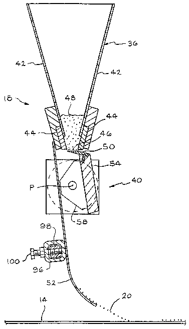
As shown in Figs. 2 and 3, the blend drop dispensers 18 are generally
comprised of
a hopper 36 and a mechanism, generally indicated at 40 for metering and
delivering
granules from the hopper 36 onto the asphalt coated sheet 14 to form the blend
drops 20.
The hopper 36 is generally comprised of converging walls 42, and optionally
can be
provided with wear plates 44 that can be replaced when desired. Granules 48
are fed to
the hopper from granule supplies, not shown. The discharge slot 46 is the gap
or space
between the lowermost edges of the wear plates 44. In the event that the wear
plates are
not used, the discharge slot will be defined by the lowermost edges of the
hopper walls 42.
Optionally, the walls 42 and/or the wear plates 44 can be provided with an
adjustability
feature to enable changes in the size or shape of the discharge slot 46. The
hopper 36
extends transversely across the moving asphalt coated sheet 14, and the
discharge slot 46
is generally linear across the width of the shingle machine or portions of the
shingle
machine. It is to be understood that some shingle machines will be set up to
make
multiple shingles simultaneously, and blend drops are not needed in the
headlap areas of
the shingles. Therefore, although the discharge slot is typically continuous
extending
transverse to the machine direction, i.e., across the asphalt coated sheet,
the hopper 36 is
provided with dividers, not shown, that act to allow delivery of the granules
the desired
transverse sections of the slot 46.
The mechanism 40 for metering and delivering granules to form the blend drops
20
includes a movable gate 50 for opening and closing the discharge slot 46 of
the hopper 36,
and a chute 52 for directing the blend drops 20 onto the asphalt coated sheet
14. The gate
50 acts as a valve for dispensing the granules from the hopper 36. Preferably,
the gate 50
is made of a hard material, such as steel. The gate 50 is mounted for
reciprocal movement
on a gate support member 54 in close proximity to the discharge slot 46 of the
hopper so
that reciprocation of the gate opens and closes the discharge slot to meter
the granules 48
from the hopper 36. The spacing between the gate and the bottom of the
adjustable plates
44 is approximately 1/8 inches (.3175 cm). The gate support member 54 is
preferably a
generally flat bar, and is mounted for rotation about a pivot point P. The
gate support
member can be any structural member suitable for mounting the gate 50 for
reciprocal
movement. Ideally, the gate support member is oriented generally vertically so
that it will
not interfere with the blend drop granules falling from the hopper.
Preferably, the gate
support member 54 is made of a strong but light weight material, such as
aluminum.
6
CA 02457927 2004-02-18
WO 03/020441 PCT/US02/26410
The rotation of the gate support member 54 causes the gate 50 to travel
through an
arc, about pivot point P. Since the discharge slot 46 is typically less than
an inch in width,
the arc necessary for travel of the gate to open and close the discharge slot
46 is less than
about 30 degrees, and preferably less than about 20 degrees. In a typical
construction, the
width W of the discharge slot is about 0.65 inches (1.651 cm), and the
reciprocal
movement of the gate is about 0.75 inches (1.905 cm). While the reciprocal
movement of
the gate has 'been shown to be movement along an arc, it is to be understood
that the
reciprocal movement can be in a plane, i.e., linear. Further, while the
arcuate movement
of the gate 50 shown in the drawings is a reciprocal movement, it is to be
understood that a
plurality of gates, not shown, could be used to pass across the slot 46
seriatim to open and
close the slot to create blend drops. W such an arrangement, the plurality of
gates could be
in the form of a wheel, not shown, having the gates at its circumference, or
the gates could
be in the form of a conveyor belt, not shown, containing the plurality of
gates and
positioned to pass directly beneath the discharge slot.
As shown in Figs. 3 and 4, the gate support member 54 is attached at its ends
56 to
a pair of rotatably mounted mounting blocks 58, only one of which is shown in
Fig. 4.
The mounting blocks 58 are mounted on shafts 60 coincident with pivot point P,
and the
shafts 60 are mounted in bearings 62 for rotation about pivot point P. One of
the shafts is
connected through a coupler 64 to a motor 66, which preferably is a servo
motor. A
controller 70 is connected to the servo motor to control its operation.
Although the gate is
illustrated as being reciprocated through an arcuate path with a servo motor
66, it is to be
understood that any suitable means for reciprocating the gate to open and
close the
discharge slot 46 can be used. For example, the gate could be reciprocated
with a linear
servo motor, a linear actuator or a cam/linkage mechanism. An important
advantage of
the servo motor and connections shown in the drawings is that rotary indirect
movement
or play associated with prior art rotational devices is nearly eliminated. The
connection to
the motor 66 is practically direct, and unintended rotational freedom of
movement is
limited to a single precision rotary coupling 62 and the rotary flex in the
shafts 60.
Further, the light weight nature of the gate support member 54 and the gate 50
minimizes
inertia, thereby enabling faster and more precise movement of the gate.
Figs. 3-5 illustrate that the gate 50 is moiulted on the gate support member
54 by
means of threaded fasteners, such as screw 72. Other types of mounting for the
gate can
be used. The gate 50 has a screw aperture 74, and there is a threaded aperture
76 in the
edge 78 of the gate support member 54 to allow the screw to hold the gate 50
firmly in
7
CA 02457927 2004-02-18
WO 03/020441 PCT/US02/26410
place on the support member 54. A preferred shape for the top surface 80 of
the gate 50 is
a curved surface. For ease of manufacturing, a curved surface can be
approximated by
using a number of planar surfaces extending transverse to the machine
direction, such as
planar surfaces 84, 86 and 88. Any number of planar surfaces can be used to
approximate
a curved surface. The three planar surfaces 84, 86 and 88 are at acute angles
to each other,
forming a substantially curved upper surface.
As shown in Fig. 5, the cross-sectional shape of the gate 50 is elongated,
with a
leading edge 90 and a shank portion 92. It is preferred that the leading edge
90 be
relatively thin to minimize the scattering of the blend drop granules as the
gate rotates or
reciprocates to close the discharge slot 46. The scattered granules are
intercepted by the
chute 52. Preferably, the thickness t of the leading edge 90 is within the
range of from
about 0.2 to about 1.5 times the median diameter of the granules. Typical
prime granules
have a size distribution allowing approximately 95 percent of the granules to
pass through
a U.S. No. 12 sieve, which has orifices having a diameter on the order of 65
mils. Further,
typical prime granules have a size distribution allowing approximately 42
percent of the
granules to pass through a U.S. No. 16 sieve, which has orifices having a
diameter on the
order of about 46 mils. From this, an assumption can be made that the prime
granules
have a median diameter of about 50 mils. More preferably, the thickness of
leading edge
90 is less than about 50 mils, and most preferably less than about 20 mils.
The shank portion 92 of the gate extends back from the leading edge 90 of the
gate
for a distance that is as great as, or nearly as great as the width W of the
discharge slot 46.
Further, the thickness T of the shank portion 92 is preferably less than about
400 mils.
The purpose of such a thin and elongated gate structure is that the gate must
not bump into
or interfere with the uppermost granules in a vertically oriented, falling
blend drop when
the gate is in the process of moving across the discharge slot to close off
the flow of
granules. Even more preferably, the thiclmess T of the shank portion 92 is
less than about
200 mils.
In operation, the hopper 36 of the blend drop dispenser 18 is supplied with a
supply of granules 48. The discharge slot 46 is kept closed by the gate 50,
thereby
preventing the granules from being discharged. The asphalt coated sheet 14 is
being
driven beneath the blend drop dispensers 18. When a blend drop is to be
deposited onto
the asphalt coated sheet, the controller 70 causes the servo motor to rotate,
thereby rotating
the gate 50 to open the discharge slot. With the discharge slot open, the
granules fall
CA 02457927 2004-02-18
WO 03/020441 PCT/US02/26410
downwardly. When the flow of granules is to be stopped, the controller signals
the servo
motor 66 to rotate the gate 50 back across the discharge slot 46 to close it.
As the gate closes the discharge slot 46, the leading edge 90 of the gate 50
will
strike some of the granules, knocking them sideways into the chute 52. These
granules
will slide down the chute and remain a part of the blend drop. The chute may
be provided
with side walls, not shown, to maintain the granules in the proper lane.
Further, as shown
in Fig. 3 the chute 52 may be mounted using a steel channel 96 that extends
transversely
across the shingle machine, and is mounted on a stationary inner channel 98.
The charnel
96 may be provided with clamps 100 to fix the position of the chute after the
chute is
given the desired transverse position.
The use of the controller 70 and a means, such as the servo motor 66, for
reciprocating the gate 50, allows several beneficial operating features
according to the
invention. The use of a servo motor enables the controller to detect the exact
position of
the gate at all times, and therefore the controller can precisely control the
exact position of
the gate with respect to the discharge slot. The controller can be programmed
to operate
the gate for opening the discharge slot to an extent less than completely
open. For
example; the controller can provide for opening the slot to a half open
position. This
would allow granules to be discharged at approximately half the maximum
possible rate.
This method enables the granules from the hopper to be metered out in a
controlled
fashion, as dictated by the controller 70. This ability to move the gate to
the extent
necessary to achieve a selected percentage of the slot being opened allows
great flexibility
in operating the shingle machine. A practical application of tlus feature is
that when the
speed of the substrate or asphalt coated sheet 14 is known, such as by the use
of a line
speed detector 102, as shown in Fig. l, the extent of opening of the slot by
the gate can be
controlled to meter the granules falling from the hopper in response to the
speed of the
substrate. Line speed detectors are well known in the art. Accordingly, as the
line speed
increases, the controller will operate the gate so that it will open the slot
to a more open
position. It is desirable to have a relatively constant flow rate of granules,
within the range
of from about 1.0 to about 1.6 grams of granules per square inch of substrate,
regardless of
the speed of the substrate. Typically, only about 1.0 gram of granules remains
on the
asphalt coated sheet after complete processing.
Another feature of the invention pertains to the ability of the controller to
control
the velocity and/or acceleration rate of the gate 50 during the opening and
closing of the
discharge slot 46. In general, as the line speed of the asphalt coated sheet
14 increases, the
9
CA 02457927 2004-02-18
WO 03/020441 PCT/US02/26410
acceleration rate of the gate 50 during opening and closing of the discharge
slot must be
increased to maintain a sharp-edged blend drop on the asphalt coated sheet.
However,
there are instances where it is desirable to control the velocity and/or
acceleration rate of
the gate 50. For example, where a blend drop having a feathering or smear of
blend drop
granules is required at a low line speed, the gate may be controlled to
accelerate at a low
rate, thereby mimicking the visual effect of the smear of granules at a high
line speed.
There are reasons for limiting the acceleration rate of the gate. Acceleration
of the
gate during opening of the slot at too high a rate can cause an undesirable
initial slug or
excess amount of granules. Also, when the gate is closed, excessive
acceleration rates for
the gate will knock more of the granules into the contact with the chute 52,
thereby
disturbing the visual uniformity of the granules at the rear or tail of the
blend drop.
Finally, some blend drop patterns may require different velocities and
acceleration rates
for the gate. It is preferred that the acceleration and deceleration rates be
kept at a level
lower than about 3 g, and more preferably at approximately 2 g. Also,
preferably the
velocity of the gate during the closing of the slot is controlled so that it
does not exceed
about 130 ft./min (39.624 cm). This minimizes the amount of granules that are
scattered
by the leading edge of the gate.
A further aspect of the present invention is that the controller can be
programmed
to control the acceleration and velocity of the gate independently of the
controlling of the
extent of the opening of the slot by the gate. This independent control of the
two
functions, acceleration of the gate and degree of opening of the slot,
provides great
flexibility to the operators of the shingle machine. An example of how this
could work is
illustrated in Fig. 6. At time zero, the gate begins to accelerate at a
constant rate. The gate
velocity increases from zero to a desired level. Then the acceleration becomes
zero and
the gate is moving at a constant velocity, as evidenced by the flat part of
the curve in Fig.
6. Finally, the gate decelerates so that it comes to rest, with a velocity of
zero. Preferably,
the acceleration drops to zero, i.e., the velocity levels off, when the
velocity reaches a
value that is within the range of from about 10 to about 190 ft./min (3.048 to
about 57.912
m./min). During manufacturing of shingles having a need for relatively precise
blend
drops, such as laminated shingles with a slate or three-dimensional look, the
leveling off
velocity is at the high end of the range, such as greater than about 90
ft./min (27.432 m).
For manufacturing shingles where a more muted blend drop is needed, such as
classic
three-tab shingles, the leveling off velocity is at the low end of the range,
such as less than
about 30 ft./min (9.144 m).
CA 02457927 2004-02-18
WO 03/020441 PCT/US02/26410
The principle and mode of operation of this invention have been described in
its
preferred embodiments. However, it should be noted that this invention can be
practiced
otherwise than as specifically illustrated and described without departing
from its scope.
11