Language selection

Search

Patent 2458005 Summary

Third-party information liability

Some of the information on this Web page has been provided by external sources. The Government of Canada is not responsible for the accuracy, reliability or currency of the information supplied by external sources. Users wishing to rely upon this information should consult directly with the source of the information. Content provided by external sources is not subject to official languages, privacy and accessibility requirements.

Claims and Abstract availability

Any discrepancies in the text and image of the Claims and Abstract are due to differing posting times. Text of the Claims and Abstract are posted:

  • At the time the application is open to public inspection;
  • At the time of issue of the patent (grant).
(12) Patent: (11) CA 2458005
(54) English Title: FACIA SYSTEM
(54) French Title: BORDURE DE TOIT
Status: Term Expired - Post Grant Beyond Limit
Bibliographic Data
(51) International Patent Classification (IPC):
  • E4D 13/15 (2006.01)
(72) Inventors :
  • BROCHU, STEPHANE (Canada)
  • BROCHU, GUY (Canada)
(73) Owners :
  • STEPHANE BROCHU
  • GUY BROCHU
(71) Applicants :
  • STEPHANE BROCHU (Canada)
  • GUY BROCHU (Canada)
(74) Agent: ROBIC AGENCE PI S.E.C./ROBIC IP AGENCY LP
(74) Associate agent:
(45) Issued: 2012-07-10
(22) Filed Date: 2004-02-17
(41) Open to Public Inspection: 2005-08-17
Examination requested: 2009-01-09
Availability of licence: N/A
Dedicated to the Public: N/A
(25) Language of filing: English

Patent Cooperation Treaty (PCT): No

(30) Application Priority Data: None

Abstracts

English Abstract

A facia system for use in a building structure, the facia system having first and second members, a first member having a portion thereof secured to a roof and a drip edge, a second portion being adapted to extend generally vertically and having first cooperative locking section associated therewith, the second member being a facia member which has second cooperative locking arrangement at an upper portion thereof such that when the first and second cooperative locking portions hold the facia member in position, the second member also having an inwardly extending flange arrangement to abut and adjoining soffit.


French Abstract

Il s'agit d'une bordure de toit pour structure de bâtiment. Cette bordure est pourvue de premier et second éléments, le premier élément ayant une partie fixée à un toit et un larmier, la seconde partie étant adaptée pour s'étendre généralement à la verticale et ayant une première section de verrouillage coopérative associée. Le second élément est un élément de bordure de toit ayant un second montage de verrouillage coopératif à une partie supérieure, de sorte que lorsque les première et seconde parties de verrouillage coopératives maintiennent en place l'élément de bordure de toit, le second élément présente également un montage de jupe s'étendant vers l'intérieur pour être contigu à l'intrados.

Claims

Note: Claims are shown in the official language in which they were submitted.


The embodiments of the invention in which an exclusive property or privilege
is
claimed are defined as follows:
1. A fascia system comprising:
a first member and a second member;
said first member having an upper section designed for securement to an upper
surface
of a roof member; a drip edge formed at an extremity of said upper section;
a transition section extending inwardly and downwardly from said first
section;
a lower section extending substantially vertically from said transition
section, said
lower section having first cooperative locking means associated therewith;
said second member comprising a fascia member having second cooperative
locking
means at an upper portion thereof, said first and second cooperative locking
means being
designed such that said first cooperative locking means engage said second
cooperative
locking means to thereby hold said fascia member in position, said second
member having a
generally planar central portion; and
an inwardly extending flange arrangement at a bottom end of said generally
planar
portion to abut an adjoining soffit.
2. The fascia system of claim 1 wherein said upper section of said first
member includes
a first portion for securement to said roof and a second portion angled
downwardly with
respect to said first portion.
3. The fascia system of claim 1 wherein said first member and second member
are
formed of a metallic sheet material.
4. The fascia system of claim 3 wherein said sheet material is aluminum.
5. The fascia system of claim 1 further including a tensioning member, said
tensioning
member being designed to be secured to a building structure and to contact
said inwardly
-9-

extending flange arrangement of said second member and to thereby maintain a
pressure
thereon.
6. In a building having a roof structure including a plurality of sloping
rafters extending
beyond an adjacent wall structure and which sloping rafters terminate in a
fascia and wherein
said rafters are covered by a sheet material and a roofing material, the
improvement
comprising a fascia system, said fascia system comprising:
a first member and a second member;
said first member having an upper section secured to a top surface of said
sheet
material under said roofing material;
a drip edge formed at an extremity of said upper section, said drip edge being
spaced
outwardly from said rafters and roofing material;
a transition section intermediate said upper section and a lower section;
said lower section including a generally vertically extending portion, said
generally
vertically extending portion having first cooperative locking means thereon;
said second
member comprising a fascia member having second cooperating locking means at
an upper
portion thereof, said first and second cooperating locking members being
engaged such that
said fascia member is held in position;
said second member having a generally planar central portion; and
an inwardly extending flange arrangement at a bottom end of said generally
planar
portion, said inwardly extending flange abutting an adjoining soffit.
7. The improvement of claim 6 wherein said first member and said second member
are
formed of a metallic sheet material.
8. The improvement of claim 6 further including a tensioning member, said
tensioning
-10-

member being secured to said roof structure whereby said tensioning member
extends
downwardly to abut said inwardly extending flange arrangement.
9. A fascia system comprising:
a first member and a second member; said first member having an upper section
designed for securement to an upper surface of a roof member;
a drip edge formed at an extremity of said upper section; a transition section
having
a first portion extending upwardly and inwardly from said drip edge and a
second portion
extending downwardly;
a lower section extending substantially vertically from said transition
section, said
lower section having first cooperative locking means associated therewith;
said second member comprising a fascia member having second cooperative
locking
means at an upper portion thereof, said first and second cooperative locking
means being
designed such that said first cooperative locking means engage said second
cooperative
locking means to thereby hold said fascia member in position, said second
member having a
generally planar central portion; and
an inwardly extending flange arrangement at a bottom end of said generally
planar
portion to abut an adjoining soffit.
10. A fascia system comprising:
a first member and a second member;
said first member having an upper section designed for securement to an upper
surface
of a roof member;
a drip edge formed at an extremity of said upper section;
a transition section extending inwardly and downwardly from said first
section;
-11-

a lower section extending substantially vertically from said transition
section, said
lower section having first cooperative locking means associated therewith;
said second member comprising a fascia member having second cooperative
locking
means at an upper portion thereof, said first and second cooperative locking
means being
designed such that said first cooperative locking means engage said second
cooperative
locking means to thereby hold said fascia member in position, said second
member having a
generally planar central portion, said second cooperative locking means
comprising a
plurality of outwardly extending projections and said first cooperative
locking means
comprising recess portions to receive said projections such that said second
member is
supported by said first member; and
an inwardly extending flange arrangement at a bottom end of said generally
planar
portion to abut an adjoining soffit.
11. A fascia system comprising:
a first member and a second member;
said first member having an upper section designed for securement to an upper
surface
of a roof member;
a drip edge formed at an extremity of said upper section;
a transition section extending inwardly and downwardly from said first
section;
a lower section extending substantially vertically from said transition
section, said
lower section having first cooperative locking means associated therewith;
said second member comprising a fascia member having second cooperative
locking
means at an upper portion thereof, said first and second cooperative locking
means being
designed such that said first cooperative locking means engage said second
cooperative
-12-

locking means to thereby hold said fascia member in position, said second
member having a
generally planar central portion, said second member having a plurality of
spacing projections
formed on said generally planar central portion; and
an inwardly extending flange arrangement at a bottom end of said generally
planar
portion to abut an adjoining soffit.
-13-

Description

Note: Descriptions are shown in the official language in which they were submitted.


CA 02458005 2004-02-17
FACIA SYSTEM
FIELD OF THE INVENTION
The present invention relates to a facia system for buildings.
BACKGROUND OF THE INVENTION
The facia is that part of a building where the roof terminates. Typically,
most
residences and relatively small commercial or industrial establishments
utilise a sloping
roof. The roof structure includes a plurality of rafters upon which a solid
material such as
plywood or the like is placed. Subsequently, the weatherproofing component is
applied on
top thereof, the weatherproofing component typically being asphalt tiles
although sheet
metal, shakes, other types of tiles, and composite materials are also
utilised.
At the point where the rafters terminate, a facia is installed and extends
along the
ends of the rafters. Typically, the facia may comprise a wooden member and/or
a metal
member secured thereto. Typically, the metal member comprises an L-shaped
member
which extends along the facia and inward towards the soffit portion of the
eaves.
One of the problems which is frequently encountered is the finishing
arrangement
such that water will not run back underneath the shingles or other material at
the end of
the roof. As a result, specially designed drip edges are frequently installed;
however,
many of these drip edges do not function properly. Thus, it is well known by
installers of
gutters or eaves troughs that there is almost inevitably some water leakage
between the
back wall of the gutter and the facia.
SUMMARY OF THE INVENTION
It is an object of the present invention to provide a facia arrangement
wherein the
problem with an effective drip edge is obviated.
-1-

CA 02458005 2004-02-17
It is a further object of the present invention to provide a facia system
wherein a
facia member has an adjustable height.
It is a further object of the present invention to provide a facia system
which is
aesthetic and easily installed.
According to one embodiment of the present invention, there is provided a
facia
system comprising a first member and a second member. The first member has an
upper
section designed for securement to a roof, and a drip edge formed at an
extremity of the
upper section. A second lower section includes a generally vertically
extending portion,
the generally vertically extending portion having first cooperative locking
means
associated therewith. The second member comprises a facia member having second
cooperating locking means at an upper portion thereof, the first and second
cooperative
locking means being designed such that first cooperative locking means hold
the facia
member in position. The second member has a generally planer central portion
and an
inwardly extending flange arrangement at a bottom end of the generally planer
portion
which abut an adjoining soffit.
According to a further aspect of the present invention, there is provided in a
building having a roof structure including a plurality of sloping rafters
extending beyond
an adjacent wall structure and which sloping rafters terminate in a facia, and
wherein the
rafters are covered by a roofing material, the improvement comprising a facia
system, the
facia system comprising a first member and a second member, the first member
having an
upper section secured to the rafters under the roofing material; a drip edge
formed at an
extremity of the upper section; a second lower section which includes a
generally
vertically extending portion, the generally vertically extending portion
having first
-2-

CA 02458005 2004-02-17
cooperative locking means thereon, the second member comprising a facia member
having second cooperative locking means at an upper portion thereof, the first
and second
cooperating locking members being engaged such that the facia member is held
in
position, the second member having a generally planar central portion; and an
inwardly
extending flange arrangement at a bottom end of the generally planar portion,
the inwardly
extending flange abutting an adjoining soffit.
The facia system of the present invention would typically be manufactured from
a
sheet metal such as aluminum or an aluminum alloy which can easily be formed
into
various configurations by known methods. However, it is also within the scope
of the
invention to use other materials such as a plastic material which could be
extruded or
otherwise formed into the desired configurations.
As aforementioned, the facia system includes a first member and a second
member,
the first member being secured to the building structure and being designed to
support the
second member in a desired position.
In a preferred embodiment of the invention, the first member has an upper
section
which is designed for securement to the roof; the upper section would
conventionally be
secured to the top of the sheet material attached to the rafters - i.e.
plywood or other
composite products. The means of securing may be any conventional including
adhesives
and/or mechanical securement means such as nails and screws.
The upper section preferably includes a first portion which is secured to the
roof as
aforementioned and a second portion which will extend outwardly from the roof
edge and
which second portion is slightly angled with respect to the first portion. It
is the second
portion which will terminate in a drip edge.
-3-

CA 02458005 2004-02-17
There is also provided a lower section which includes a generally vertically
extending portion designed to lie adjacent the facia's structure. The lower
section also
includes a portion extending between the drip edge and the vertically
extending portion.
In this respect, from the drip edge, there is preferably provided a segment
which extends
upwardly to thereby define the drip edge and which will then extend downwardly
to the
generally vertically extending portion.
The generally vertically extending portion will have a first cooperative
locking
means associated therewith. Although many such cooperative locking means can
be
envisaged, one of the simpler structures will include a formed hook and recess
engagement as will be discussed hereinbelow.
The second member is the portion which covers the facia. At the upper end, the
second member is provided with a second cooperative locking means designed to
engage
with the first cooperative locking means. Conveniently, as aforementioned,
this may be
provided by a plurality of hooks or projections extending outwardly from the
second
member and which are designed to engage within recesses or other supports of
the first
cooperative locking means. An advantage of such an arrangement is that they
may easily
be provided by conventional metal forming equipment well known in the art.
Preferably, the first and second cooperative locking means are adjustable with
respect to each other such that they may be engaged in different positions. By
so doing, a
arrangement is provided for differing facia heights.
The second member, as aforementioned, actually forms or covers the facia and
as
such, is substantially plainer in nature although certain embossing or spacing
projections
may be provided as will be discussed with respect to the preferred embodiment.
-4-

CA 02458005 2004-02-17
At the lower end, the second member is provided with an inwardly extending
portion which is designed to abut the soffit structure of the building. In a
particularly
preferred arrangement, the lower portion of the second member is formed to
have a recess
at a lower extremity defined by the lower portion of the vertically extending
wall and the
inwardly extending portion. This recess may be utilised to accommodate a
tensioning
member which is secured to the roof structure and which engages the lower
portion of the
second member. To this end, the tensioning member will, as aforementioned, be
secured
to the roof structure and have a downwardly extending portion designed to seat
within the
aforesaid recess. Preferably, the tensioning member has a certain resilience
and to this
end, may be provided with a sinusoidal portion to provide the desired
resiliency.
BRIEF DESCRIPTION OF THE DRAWINGS
Having thus generally described the invention, reference will be made to the
accompanying drawings illustrating an embodiment thereof, in which:
Figure 1 is a perspective view of a facia and soffit arrangement employing the
facia
system of the present invention;
Figure 2 is a side elevational view of the facia system of the present
invention
illustrating the mounting thereof on a portion of a structure;
Figure 3 is a view similar to Figure 2 with the structural components of the
housing
structure being removed and showing the adjustability of the system.
Figure 4 is a side elevational view of the upper member of the facia system;
Figure 5 is a perspective view thereof;
Figure 6 is a side elevational view of the lower member of the facia system
according to the present invention;
-5-

CA 02458005 2004-02-17
Figure 7 is a perspective view thereof;
Figure 8 is side elevational view of a tensioning member which can be utilised
in
the facia system of the present invention; and
Figure 9 is a perspective view thereof.
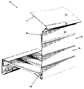
Referring to the drawings in a greater detail and by reference characters
thereto, the
facia system of the present invention is generally designated by reference
numeral 10 and
includes a first upper member designated by reference numeral 12 and which
will now be
referred to.
First upper member 12 includes a first upper section generally designated by
reference numeral 11 and which includes a planer portion 14 which is designed
to lie
adjacent to a roof structure R such as is employed in a conventional house. In
this respect,
it will be understood that under normal circumstances, planer portion 14 will
lie on the
roof under the shingles or other similar roof covering.
From planer portion 14, upper section 11 includes a downwardly inclined
portion 16 which is angled with respect to planar portion 14 and which
terminates in a
drip edge 18.
From drip edge 18, first upper member 12 has an upwardly and inwardly
extending
portion 20 which ensures the proper formation of the drip edge 18.
Subsequently, there is
provided a second downwardly inclined portion 22 which terminates in an outer
vertical
wall 24. The material forming first upper member 12 then is folded to have an
inner
vertical wall 26 which is formed with a plurality of recesses 28.
A second lower member generally designated by reference numeral 30 has an
upper portion 32 with a plurality of hook-shaped projections 34 formed
therein.
-6-

CA 02458005 2004-02-17
Second lower member 30 also includes a main planer portion generally
designated
by reference numeral 36 and which has formed therein a plurality of spacer
projections 38.
At its lower end, second lower member 30 has an inwardly extending flange
portion
generally designated by reference numeral 40. Inwardly extending flange
portion 40 has a
first horizontal section 42 which joins an arcuately upwardly concave portion
44. There is
thus formed a cavity generally designed by reference numeral 45. At the end of
arcuate
section 44, there is provided a diagonally upwardly extending section 46 which
terminates
in a horizontal end portion 48.
As shown in Figures 2 and 3, there is also provided a spacer and tensioning
member 50. Spacer and tensioning member 50 is illustrated in Figures 8 and 9
includes an
upper planer portion 52, and a sinuous section generally designated by
reference numeral
54 and which includes a plurality of arcuate sections in an overall S-shaped
configuration.
Sinuous section 54 terminates in a bottom section generally designated by
reference
numeral 56 and which is designed to seat within cavity 45.
In use, and referring to Figures 2 and 3, first member 12 is installed in a
position on
roof R with planar portion 14 being secured thereto by suitable means (not
shown). This
thus provides a drip edge 18 with vertical portions 24 and 26 lying parallel
to a facia
board F.
Spacer and tensioning member 50 may then be secured in the position to facia
board F and subsequently, second member 30 is hung in a position and supported
by first
member 12. In this regard, hook shaped projections 34 are engaged within
recesses 28 of
first member 12. Spacer and tensioning member 50 seats within cavity or a
pocket 45 of
second member 30 and maintains a tension on second member 30 to ensure hook
shaped
-7-

CA 02458005 2011-05-31
projections 34 remain engaged within recesses 28. Inwardly extending flange
portion 40
is arranged to engage a soffit S and support one edge thereof. The other edge
of soffit S
is supported by a suitable supporting member 74 as is disclosed in U.S.
Application serial
number 10/797,830 published as Publication No. 2005/0223657.
As seen in Figure 3, the structure of the present invention provides for
adjustability as shown in the dashed and complete lines. Thus, a first member
12 may
assume different positions depending upon the particular engagement of
projections 34
with recesses 28.
It will be understood that the above described embodiments are for purposes of
illustration only and that changes and modifications may be made thereto
without
departing from the spirit and scope of the invention.
-8-

Representative Drawing
A single figure which represents the drawing illustrating the invention.
Administrative Status

2024-08-01:As part of the Next Generation Patents (NGP) transition, the Canadian Patents Database (CPD) now contains a more detailed Event History, which replicates the Event Log of our new back-office solution.

Please note that "Inactive:" events refers to events no longer in use in our new back-office solution.

For a clearer understanding of the status of the application/patent presented on this page, the site Disclaimer , as well as the definitions for Patent , Event History , Maintenance Fee  and Payment History  should be consulted.

Event History

Description Date
Inactive: Expired (new Act pat) 2024-02-19
Appointment of Agent Request 2023-05-02
Revocation of Agent Request 2023-05-02
Appointment of Agent Request 2023-05-02
Revocation of Agent Request 2023-05-02
Revocation of Agent Requirements Determined Compliant 2023-03-02
Inactive: Office letter 2023-03-02
Appointment of Agent Requirements Determined Compliant 2023-03-02
Inactive: Office letter 2022-11-02
Revocation of Agent Request 2022-09-14
Revocation of Agent Requirements Determined Compliant 2022-09-14
Appointment of Agent Requirements Determined Compliant 2022-09-14
Appointment of Agent Request 2022-09-14
Inactive: Adhoc Request Documented 2021-09-29
Revocation of Agent Request 2021-07-14
Appointment of Agent Request 2021-07-14
Revocation of Agent Requirements Determined Compliant 2021-04-01
Appointment of Agent Requirements Determined Compliant 2021-04-01
Common Representative Appointed 2019-10-30
Grant by Issuance 2012-07-10
Inactive: Cover page published 2012-07-09
Pre-grant 2012-04-20
Inactive: Final fee received 2012-04-20
Notice of Allowance is Issued 2012-03-07
Letter Sent 2012-03-07
4 2012-03-07
Notice of Allowance is Issued 2012-03-07
Inactive: Approved for allowance (AFA) 2012-02-29
Amendment Received - Voluntary Amendment 2012-01-20
Inactive: S.30(2) Rules - Examiner requisition 2011-10-18
Amendment Received - Voluntary Amendment 2011-05-31
Inactive: S.30(2) Rules - Examiner requisition 2011-03-08
Letter Sent 2009-02-12
Request for Examination Received 2009-01-09
Request for Examination Requirements Determined Compliant 2009-01-09
All Requirements for Examination Determined Compliant 2009-01-09
Application Published (Open to Public Inspection) 2005-08-17
Inactive: Cover page published 2005-08-16
Inactive: First IPC assigned 2004-04-20
Application Received - Regular National 2004-03-22
Inactive: Filing certificate - No RFE (English) 2004-03-22
Small Entity Declaration Determined Compliant 2004-02-17

Abandonment History

There is no abandonment history.

Maintenance Fee

The last payment was received on 2012-01-20

Note : If the full payment has not been received on or before the date indicated, a further fee may be required which may be one of the following

  • the reinstatement fee;
  • the late payment fee; or
  • additional fee to reverse deemed expiry.

Patent fees are adjusted on the 1st of January every year. The amounts above are the current amounts if received by December 31 of the current year.
Please refer to the CIPO Patent Fees web page to see all current fee amounts.

Fee History

Fee Type Anniversary Year Due Date Paid Date
Application fee - small 2004-02-17
MF (application, 2nd anniv.) - small 02 2006-02-17 2006-02-06
MF (application, 3rd anniv.) - small 03 2007-02-19 2007-02-13
MF (application, 4th anniv.) - small 04 2008-02-18 2008-01-17
Request for examination - small 2009-01-09
MF (application, 5th anniv.) - small 05 2009-02-17 2009-01-09
MF (application, 6th anniv.) - small 06 2010-02-17 2010-01-05
MF (application, 7th anniv.) - small 07 2011-02-17 2011-01-26
MF (application, 8th anniv.) - small 08 2012-02-17 2012-01-20
Final fee - small 2012-04-20
MF (patent, 9th anniv.) - small 2013-02-18 2013-02-07
MF (patent, 10th anniv.) - small 2014-02-17 2014-02-14
MF (patent, 11th anniv.) - small 2015-02-17 2015-02-02
MF (patent, 12th anniv.) - small 2016-02-17 2016-02-05
MF (patent, 13th anniv.) - small 2017-02-17 2017-01-23
MF (patent, 14th anniv.) - small 2018-02-19 2018-02-09
MF (patent, 15th anniv.) - small 2019-02-18 2019-02-08
MF (patent, 16th anniv.) - small 2020-02-17 2020-02-06
MF (patent, 17th anniv.) - small 2021-02-17 2021-02-01
MF (patent, 18th anniv.) - small 2022-02-17 2022-02-01
MF (patent, 19th anniv.) - small 2023-02-17 2023-02-17
Owners on Record

Note: Records showing the ownership history in alphabetical order.

Current Owners on Record
STEPHANE BROCHU
GUY BROCHU
Past Owners on Record
None
Past Owners that do not appear in the "Owners on Record" listing will appear in other documentation within the application.
Documents

To view selected files, please enter reCAPTCHA code :


To view images, click a link in the Document Description column (Temporarily unavailable). To download the documents, select one or more checkboxes in the first column and then click the "Download Selected in PDF format (Zip Archive)" or the "Download Selected as Single PDF" button.

List of published and non-published patent-specific documents on the CPD .

If you have any difficulty accessing content, you can call the Client Service Centre at 1-866-997-1936 or send them an e-mail at CIPO Client Service Centre.


Document
Description 
Date
(yyyy-mm-dd) 
Number of pages   Size of Image (KB) 
Description 2004-02-16 8 347
Abstract 2004-02-16 1 18
Claims 2004-02-16 3 97
Drawings 2004-02-16 6 124
Representative drawing 2005-07-19 1 18
Cover Page 2005-08-01 1 44
Description 2011-05-30 8 347
Claims 2011-05-30 3 94
Claims 2012-01-19 5 183
Cover Page 2012-06-10 2 49
Filing Certificate (English) 2004-03-21 1 158
Reminder of maintenance fee due 2005-10-17 1 109
Reminder - Request for Examination 2008-10-19 1 117
Acknowledgement of Request for Examination 2009-02-11 1 176
Commissioner's Notice - Application Found Allowable 2012-03-06 1 162
Fees 2006-02-05 1 20
Correspondence 2012-04-19 1 28
Courtesy - Office Letter 2023-03-01 2 183