Language selection

Search

Patent 2458006 Summary

Third-party information liability

Some of the information on this Web page has been provided by external sources. The Government of Canada is not responsible for the accuracy, reliability or currency of the information supplied by external sources. Users wishing to rely upon this information should consult directly with the source of the information. Content provided by external sources is not subject to official languages, privacy and accessibility requirements.

Claims and Abstract availability

Any discrepancies in the text and image of the Claims and Abstract are due to differing posting times. Text of the Claims and Abstract are posted:

  • At the time the application is open to public inspection;
  • At the time of issue of the patent (grant).
(12) Patent Application: (11) CA 2458006
(54) English Title: SOFFIT STRUCTURE
(54) French Title: STRUCTURE DE SOFFITE
Status: Deemed Abandoned and Beyond the Period of Reinstatement - Pending Response to Notice of Disregarded Communication
Bibliographic Data
(51) International Patent Classification (IPC):
  • E04D 13/152 (2006.01)
  • E04D 13/17 (2006.01)
  • F24F 7/02 (2006.01)
(72) Inventors :
  • BROCHU, STEPHANE (Canada)
  • BROCHU, GUY (Canada)
(73) Owners :
  • STEPHANE BROCHU
  • GUY BROCHU
(71) Applicants :
  • STEPHANE BROCHU (Canada)
  • GUY BROCHU (Canada)
(74) Agent:
(74) Associate agent:
(45) Issued:
(22) Filed Date: 2004-02-17
(41) Open to Public Inspection: 2005-08-17
Examination requested: 2009-06-05
Availability of licence: N/A
Dedicated to the Public: N/A
(25) Language of filing: English

Patent Cooperation Treaty (PCT): No

(30) Application Priority Data: None

Abstracts

English Abstract


A soffit structure which is a sheet member having an upper surface and bottom
surface with a plurality of channels formed in the sheet members, the channels
extending inwardly from the bottom surface and being defined by at least a
pair of
opposed side walls, with apertures formed in the side walls. The side walls
are
preferably angled slightly to provide a greater degree of protection for the
apertures
formed therein.


Claims

Note: Claims are shown in the official language in which they were submitted.

The embodiments of the invention in which an exclusive property or privilege
is
claimed is defined as follows:
1. A soffit structure comprising:
a sheet member having an upper surface and a bottom surface wherein said
upper surface is designed to lie against a structural member of a building and
the
bottom surface is facing exteriorly of the building;
a plurality of channels formed is said sheet member, said channels extending
inwardly from said bottom surface, at least one channel having a pair of
opposed side
walls, said at least one channel having a plurality of apertures formed in at
least one of
said side walls.
2. The soffit structure of Claim 1 wherein each of said channels has a pair of
opposed side walls, each of said channels having apertures formed in at least
one of
said side walls.
3. The soffit structure of Claim 2 wherein all of said side walls have
apertures
formed therein.
4. The soffit structure of Claim 1 wherein said at least one channel has a
generally
U-shaped configuration with a base portion extending between said side walls,
each of
said side walls extending inwardly and rearwardly to form an angle of between
75°
and 88° with respect to said upper surface.
5. The soffit structure of Claim 1 wherein all of said channels have a
generally
U-shaped configuration comprised of a pair of opposed side walls and a bottom,
each
of said side walls extending inwardly and rearwardly at an angle of between
75° and
6

88° with respect to said upper surface, all of said walls having a
plurality of apertures
formed therein.
6. The soffit structure of Claim 1 wherein said channels each have a generally
U-
shaped configuration.
7. The soffit structure of Claim 1 wherein said sheet member is formed of a
metallic material.
8. The soffit structure of Claim 3 wherein said metallic material is aluminum.
9. The soffit structure of claim 5 wherein said channels extend transversely
of
said sheet member.

Description

Note: Descriptions are shown in the official language in which they were submitted.


CA 02458006 2004-02-17
SOFFIT STRUCTURE
FIELD OF THE INVENTION
The present invention relates to a soffit structure and more particularly,
relates to
a novel soffit structure having vent means therein.
BACKGROUND OF THE INVENTION
The use of soffit structures to provide ventilation to an attic or under the
roof area
is well known in the art. Thus, it has been known for years that ventilation
of a space
underneath a roof is necessary both during the summer and winter seasons.
During the
summer, if this area is not ventilated, the solar energy captured by the roof
would generate
excessive temperatures in the space. This will cause damage to many roofing
materials
and as well, would increase air-conditioning cost for the area below.
In winter, it is also required to ventilate the area since warm moist air
escaping
from heated areas below would, upon contact with the cold structural members,
condense.
This moisture would eventually lead to structural damage of wood components
and can
also cause dripping into the area below.
Generally, the area to be ventilated will comprise two different types of
areas.
Thus, in many sloping roof arrangements, there is provided a substantial open
area,
commonly called an attic, between the ceiling of the structure and the roof.
In such an
arrangement, different types of venting may be provided. One arrangement
provides for
a continuous vent along the ridge of the roof in conjunction with soffit
vents. This is
ideally arranged to create an air flow from the soffit through the ridge vent.
Alternatively,
various other types of vents may be provided in the end walls of the attic or
in the roof

CA 02458006 2004-02-17
itself. In all instances, the purpose is to provide a controlled airflow
through the attic
area.
In the case of cathedral ceilings, the airflow is typically between the
rafters,
extending from the soffit to an upper vent.
Generally soffits comprise a piece of sheet metal or other material through
which
apertures have been formed. While such soffits are widely accepted, they can,
under
certain conditions, permit the flow of precipitation upwardly through the
apertures.
Furthermore, the aesthetic appeal of such soffits is limited.
SLTMMARY OF THE INVENTION
It is an object of the present invention to provide a soffit structure which
is both
aesthetically attractive and overcomes the disadvantages of the prior art.
According to one aspect of the present invention, there is provided a soffit
structure comprising a sheet member having an upper surface and a bottom
surface
wherein the upper surface is designed to lie against a structural member of a
building and
the bottom surface is facing exteriorly of the building, a plurality of
channels formed in
the sheet member, the channels extending inwardly from the bottom surface, at
least one
of the channels having a pair of opposed side walls, the at least one channel
having a
plurality of apertures formed in at least one of the side walls thereof.
The soffit system of the present invention may be used in any suitable
building
structure with residential housing being the most common type of building
structure
which uses soffit ventilation. The soffit is traditionally manufactured of a
formed
metal although it is also known in the art to use plastic soffit. It sufficies
to say that
2

CA 02458006 2004-02-17
any suitable material may be utilized in the practice of the present
invention.
The channels are formed in the soffit by any suitable means, depending upon
the material. Thus, using a metallic material such as aluminum, known forming
equipment can easily form the channels. The channels preferably have a
generally U-
shaped configuration although it is even more preferred that the walls of the
channels
be angled such that they form an angle of between 75° and 88°
with respect to the
upper surface of the soffit. In other words, the base of the channel is
slightly larger
than the opening.
In the preferred embodiment, all the channels are provided with apertures
although it will be understood that only some of the channels may be provided
with
the apertures depending upon the degree of ventilation required. Similarly, it
is
preferred that the apertures be formed in both side walls of the recess.
However, it
will again be understood that only one of the walls may be provided with such
apertures.
Preferably, the apertures are sufficiently numerous and are of a size to meet
the
ventilation standards set in the building industry. Such standards are well
known in
the art. Generally, the apertures would arrange between 12 and 16 mm. The
number
of rows in each standard piece will vary depending upon the ventilation
required.
BRIEF DESCRIPTION OF THE DRAWINGS
Having thus generally described the invention, reference will be made to the
accompanying drawings illustrating an embodiment thereof, in which:
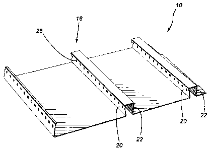
Figure I is a perspective view of a portion of a soffit structure according to
one

CA 02458006 2004-02-17
embodiment of the present invention;
Figure 2 is a side elevational view thereof; and
Figure 3 is a perspective view illustrating the soffit when used in a facia
system.
Referring to the figures in greater detail and by reference characters
thereto,
there is illustrated a soffit structure which is generally designated by
reference
numeral 10.
Soffit structure 10 has a generally planar body 12 which has an upper surface
14 and a bottom surface 16. Formed in generally planar central body portion 12
are
a plurality of generally U-shaped channels generally designated by reference
numeral 18.
Each channel 18, in the illustrated embodiment, has a pair of opposed side
walls
20, 22 which are connected by a bottom wall 24. As may best seen in Figure 2,
each
side wall 20 and 22 is angled slightly so as to form an angle of approximately
85°
between upper surface 12 and a respective side wall as indicated by angle 26.
In order to provide the ventilation, apertures 28 are provided in each of the
walls 20 and 22.
In use, the soffit may be attached by conventional means such as mechanical
fasteners or the like. However, it is preferred that the same be used in a
system
wherein it is supported at one edge by a facia support member 30 and a second
support
member 32 which is secured to the wall structure of the building.
It will be understood that the above described embodiment is for purposes of
illustration only and that changes and modif cations may be made thereto
without
4

CA 02458006 2004-02-17
departing from the spirit and scope of the invention.

Representative Drawing
A single figure which represents the drawing illustrating the invention.
Administrative Status

2024-08-01:As part of the Next Generation Patents (NGP) transition, the Canadian Patents Database (CPD) now contains a more detailed Event History, which replicates the Event Log of our new back-office solution.

Please note that "Inactive:" events refers to events no longer in use in our new back-office solution.

For a clearer understanding of the status of the application/patent presented on this page, the site Disclaimer , as well as the definitions for Patent , Event History , Maintenance Fee  and Payment History  should be consulted.

Event History

Description Date
Revocation of Agent Requirements Determined Compliant 2021-04-01
Application Not Reinstated by Deadline 2011-02-17
Time Limit for Reversal Expired 2011-02-17
Deemed Abandoned - Failure to Respond to Maintenance Fee Notice 2010-02-17
Letter Sent 2009-07-20
Reinstatement Requirements Deemed Compliant for All Abandonment Reasons 2009-06-05
Request for Examination Requirements Determined Compliant 2009-06-05
All Requirements for Examination Determined Compliant 2009-06-05
Reinstatement Request Received 2009-06-05
Inactive: Abandon-RFE+Late fee unpaid-Correspondence sent 2009-02-17
Letter Sent 2007-04-17
Application Published (Open to Public Inspection) 2005-08-17
Inactive: Cover page published 2005-08-16
Inactive: First IPC assigned 2004-04-20
Inactive: IPC assigned 2004-04-20
Application Received - Regular National 2004-03-22
Filing Requirements Determined Compliant 2004-03-22
Inactive: Filing certificate - No RFE (English) 2004-03-22
Small Entity Declaration Determined Compliant 2004-02-17

Abandonment History

Abandonment Date Reason Reinstatement Date
2010-02-17
2009-06-05

Maintenance Fee

The last payment was received on 2009-01-28

Note : If the full payment has not been received on or before the date indicated, a further fee may be required which may be one of the following

  • the reinstatement fee;
  • the late payment fee; or
  • additional fee to reverse deemed expiry.

Please refer to the CIPO Patent Fees web page to see all current fee amounts.

Fee History

Fee Type Anniversary Year Due Date Paid Date
Application fee - small 2004-02-17
MF (application, 2nd anniv.) - small 02 2006-02-17 2006-02-06
MF (application, 3rd anniv.) - small 03 2007-02-19 2007-01-22
MF (application, 4th anniv.) - small 04 2008-02-18 2008-02-04
MF (application, 5th anniv.) - small 05 2009-02-17 2009-01-28
2009-06-05
Request for examination - small 2009-06-05
Owners on Record

Note: Records showing the ownership history in alphabetical order.

Current Owners on Record
STEPHANE BROCHU
GUY BROCHU
Past Owners on Record
None
Past Owners that do not appear in the "Owners on Record" listing will appear in other documentation within the application.
Documents

To view selected files, please enter reCAPTCHA code :


To view images, click a link in the Document Description column. To download the documents, select one or more checkboxes in the first column and then click the "Download Selected in PDF format (Zip Archive)" or the "Download Selected as Single PDF" button.

List of published and non-published patent-specific documents on the CPD .

If you have any difficulty accessing content, you can call the Client Service Centre at 1-866-997-1936 or send them an e-mail at CIPO Client Service Centre.


Document
Description 
Date
(yyyy-mm-dd) 
Number of pages   Size of Image (KB) 
Abstract 2004-02-17 1 13
Description 2004-02-17 5 170
Drawings 2004-02-17 2 46
Claims 2004-02-17 2 52
Representative drawing 2005-07-20 1 10
Cover Page 2005-08-02 1 33
Filing Certificate (English) 2004-03-22 1 158
Reminder of maintenance fee due 2005-10-18 1 109
Reminder - Request for Examination 2008-10-20 1 117
Courtesy - Abandonment Letter (Request for Examination) 2009-05-26 1 165
Acknowledgement of Request for Examination 2009-07-20 1 174
Notice of Reinstatement 2009-07-20 1 168
Courtesy - Abandonment Letter (Maintenance Fee) 2010-04-14 1 172
Fees 2006-02-06 1 20
Correspondence 2007-04-17 1 14