Language selection

Search

Patent 2458022 Summary

Third-party information liability

Some of the information on this Web page has been provided by external sources. The Government of Canada is not responsible for the accuracy, reliability or currency of the information supplied by external sources. Users wishing to rely upon this information should consult directly with the source of the information. Content provided by external sources is not subject to official languages, privacy and accessibility requirements.

Claims and Abstract availability

Any discrepancies in the text and image of the Claims and Abstract are due to differing posting times. Text of the Claims and Abstract are posted:

  • At the time the application is open to public inspection;
  • At the time of issue of the patent (grant).
(12) Patent: (11) CA 2458022
(54) English Title: SAFETY SWITCH FOR A WATER DISPENSER
(54) French Title: COMMANDE DE SECURITE POUR DISTRIBUTEUR D'EAU
Status: Expired and beyond the Period of Reversal
Bibliographic Data
(51) International Patent Classification (IPC):
  • B67D 07/32 (2010.01)
  • B67D 01/08 (2006.01)
  • B67D 01/14 (2006.01)
(72) Inventors :
  • ZHENG, FANG-ZHEN (China)
(73) Owners :
  • GD MIDEA HOLDING CO., LTD.
(71) Applicants :
  • GD MIDEA HOLDING CO., LTD. (China)
(74) Agent: ADE & COMPANY INC.
(74) Associate agent:
(45) Issued: 2008-12-30
(22) Filed Date: 2004-02-19
(41) Open to Public Inspection: 2004-08-20
Examination requested: 2004-02-19
Availability of licence: N/A
Dedicated to the Public: N/A
(25) Language of filing: English

Patent Cooperation Treaty (PCT): No

(30) Application Priority Data:
Application No. Country/Territory Date
03 2 23679.4 (China) 2003-02-20

Abstracts

English Abstract

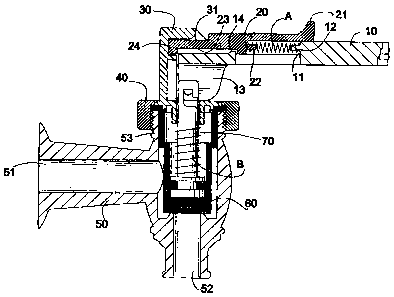
A safety switch for a water dispenser includes a sealing ring (60), a guiding rod (70) securely received in the sealing ring (60) and having a spring compressibly mounted around the guiding rod (70), a handle (10) adapted to be pivotal relative to the water dispensing tube and having a first distal end securely connected to a second distal end of the guiding rod (70), a support (30) engaged with an outer periphery defining the channel (53) and a sliding block (20) movably sandwiched between the support (30) and the handle (10) so that movement of the sliding block (20) relative to the support (30) allows the pivotal movement of the handle (10), which initiates an upward movement of the guiding rod (70) as well as the sealing ring (60) such that the communication between the inlet (51) and the outlet (52) is resumed.


French Abstract

Commande de sécurité pour refroidisseur d'eau comprenant les éléments suivants : une bague d'étanchéité (60); une tige de guidage (70) solidement maintenue dans la bague d'étanchéité (60) et autour de laquelle un ressort tendu est enroulé; une poignée (10) conçue pour pivoter par rapport au tube de distribution d'eau et dotée d'une première extrémité distale reliée à une seconde extrémité distale de la tige de guidage (70); un support (30) inséré dans un bord externe délimitant le canal (53); un coulisseau (20) pris en sandwich entre le support (30) et la poignée (10) afin que le déplacement du coulisseau (20) par rapport au support (30) permette à la poignée de pivoter (10), ce qui engage le mouvement vers le haut de la tige de guidage (70) et de la bague d'étanchéité (60) de manière à établir une communication fluidique entre l'orifice d'entrée (51) et l'orifice de sortie (52).

Claims

Note: Claims are shown in the official language in which they were submitted.


WHAT IS CLAIMED IS:
1. A safety switch for a water dispenser having a water dispensing tube with
an
inlet, an outlet in communication with the inlet and a channel in
communication with
both the inlet and the outlet, the safety switch comprising:
a sealing ring movably received in the channel to alternatively block
communication between the inlet and the outlet;
a guiding rod having a first distal end securely received in the sealing ring
and a
first spring compressibly mounted around an outer periphery of the guiding
rod;
a handle adapted to be pivotal relative to the water dispensing tube and
having a
first distal end securely connected to a second distal end of the guiding rod;
a support having a first distal end adapted to be securely engaged with an
outer
periphery defining the channel and a second distal end provided with a
receiving space;
and
a sliding block movably sandwiched between the support and the handle so that
movement of the sliding block relative to the support allows the pivotal
movement of
the handle, which initiates an upward movement of the guiding rod as well as
the sealing
ring such that the communication between the inlet and the outlet is resumed.
2. The safety switch as claimed in claim 1, wherein a second spring is
received
between the sliding block and the handle to provide a recovery force to the
sliding block.
3. The safety switch as claimed in claim 2, wherein the handle has a recessed
area defined in a bottom face of the handle and a first protrusion formed on a
side face of
the recessed area and the sliding block has a cutout defined in a bottom face
of the
sliding block and a second protrusion formed on a side face defining the
cutout to
correspond to the first protrusion of the handle such that the second spring
is received

8
between the first protrusion and the second protrusion.
4. The safety switch as claimed in claim 1, wherein the sliding block has a
bent
formed on a first distal end of the sliding block to be received in the
receiving space of
the support so that when the bent is received in the receiving space, the
handle is unable
to be pivoted relative to the support and when the bent is away from the
receiving space,
the handle is able to be pivoted to initiate the upward movement of the
guiding rod.
5. The safety switch as claimed in claim 3, wherein the sliding block has a
bent
formed on a first distal end of the sliding block to be received in the
receiving space of
the support so that when the bent is received in the receiving space, the
handle is unable
to be pivoted relative to the support and when the bent is away from the
receiving space,
the handle is able to be pivoted to initiate the upward movement of the
guiding rod.
6. The safety switch as claimed in claim 1 further comprising a cap adapted to
be threadingly connected to the outer periphery defining the channel to secure
the
engagement of the first distal end of the support with the outer periphery
defining the
channel.
7. The safety switch as claimed in claim 3 further comprising a cap adapted to
be threadingly connected to the outer periphery defining the channel to secure
the
engagement of the first distal end of the support with the outer periphery
defining the
channel.
8. The safety switch as claimed in claim 5 further comprising a cap adapted to
be threadingly connected to the outer periphery defining the channel to secure
the
engagement of the first distal end of the support with the outer periphery
defining the
channel.

Description

Note: Descriptions are shown in the official language in which they were submitted.


CA 02458022 2004-02-19
4 . 2
1 SAFETY SWITCH FOR A WATER DISPENSER
2 BACKGROUND OFTHE INVENTION
3 1. Field of the Invention
4 The present invention relates to a safety switch, and more particularly to
safety switch for a water dispenser so that an accidental touch of the safety
6 switch will not cause water to flow out of the water dispenser, thus
avoiding
7 spillage, potential injury to users etc.
8 2. Description of Related Art
9 A conventional water dispenser usually is equipped with a distilled water
flagon and a water dispensing mechanism having a switch to control water flow
11 out of the distilled water flagon. By pressing the switch, the distilled
water is
12 able to flow out of the distilled water flagon and thus the user is able to
enjoy the
13 distilled water. However, when the switch is accidentally touched, such as
14 someone brushing past the dispenser, heated water flowing out of the water
dispenser may cause a nuisance or even injury to the people, especially
children,
16 nearby the water dispenser. Therefore, to avoid such an unpleasant incident
from
17 happening, patents providing safety measurements have been introduced to
the
18 market and they do have the ability to prevent such mishap from happening.
19 However, due to the structural complexity and excessive time consumed in
assembly, cost of such safety switches is never low.
21 To overcome the shortcomings, the present invention tends to provide an
22 improved safety switch to mitigate the aforementioned problems.
23 SUMMARY OF THE INVENTION
24 The primary objective of the present invention is to provide an improved

CA 02458022 2007-01-25
3
1 safety switch which is simple in structure and easy to be assembled.
2 According to a first aspect of the invention there is provided a safety
switch for a
3 water dispenser having a water dispensing tube with an inlet, an outlet in
communication
4 with the inlet and a channel in communication with both the inlet and the
outlet, the safety
switch comprising:
6 a sealing ring movably received in the channel to alternatively block
communication
7 between the inlet and the outlet;
8 a guiding rod having a first distal end securely received in the sealing
ring and a first
9 spring compressibly mounted around an outer periphery of the guiding rod;
a handle adapted to be pivotal relative to the water dispensing tube and
having a first
11 distal end securely connected to a second distal end of the guiding rod;
12 a support having a first distat end adapted to be securely engaged with an
outer
13 periphery defining the channel and a second distal end provided with a
receiving space; and
14 a sliding block movably sandwiched between the support and the handle so
that
movement of the sliding block relative to the support allows the pivotal
movement of the
16 handle, which initiates an upward movement of the guiding rod as well as
the sealing ring
17 such that the communication between the inlet and the outlet is resumed.
18 To accomplish the foregoing objective, the safety switch of the present
invention is
19 provided with a sliding block movably received between the handle and
support so that when
the sliding block is sandwiched between the handle and the support, the handle
will not be
21 able to be pivoted to allow the water to flow out of the dispenser and when
the sliding block
22 is away from engagement with the support, the handle is able to be pivoted
to allow water to
23 flow out of the water dispenser.
24 Other objects, advantages and novel featnres of the invention will become
more
apparent from the following detailed description when taken in conjunction
with the
26 accompanying drawings.
27 SR1EF DESCRIPTION OF THE_DRAWINGS
28 Fig. 1 is a perspective view of the safety switch of the present invention;
29 Fig. 2 is an exploded perspective view showing struCtural relationship
between the

CA 02458022 2007-01-25
3a
1 handle and the sliding block;
2 Fig. 3 is a cross sectional view taken by line 3-3 of Fig. 1;
3 Fig, 4 is an operational schematic view showing the sliding block is moved
relative to
4 the handle; and
Fig. 5 is an operational schematic view showing that the handle is able to be
pivoted
6 as a consequence of the movement of the sliding block.
7 DETAILED DESCRIPTION OF THE PREFERRED EM$ODIMENT
8 With reference to Fig. 1, a safety switch in accordance with the present
invention is
9 adapted to combine with a water dispenser (not shown) with a water
dispensing tube (50).
The water dispensing tube (50) has an inlet (51) for
il

CA 02458022 2004-02-19
4
1 receiving water from the water dispenser and an outlet (52) for allowing the
2 water from the inlet (51) to flow out of the water dispensing tube (50).
3 With reference to Figs. 2 and 3, it is noted that the safety switch of the
4 present invention has a handle (10), a sliding block (20), a support (30)
sandwiching the sliding block (20) with the handle (10), a cap (40) mounted on
a
6 periphery defming a channel (53) in the water dispensing tube (50) and a
sealing
7 ring (60) received in the channel (53) to alternatively block communication
8 between the inlet (51) and the outlet (52).
9 The handle (10) has a recessed area (11) in a mediate portion of the
handle (10), a first protrusion (12) formed on a side face defining the
recessed
11 area (11) and two wings (13) extending from a distal end of the handle
(10). A
12 stop (14) is formed on a top face of the handle (10). The sliding block
(20) is
13 partially and slidably received in the recessed area (11) and has a head
(21)
14 formed on a first distal end of the sliding block (20) and on top of the
handle (10),
a second protrusion (22) formed on a side face of a bottom face of the sliding
16 block (20) to correspond to the first protrusion (11) of the handle (10), a
cutout
17 (23) defined in the bottom face of the sliding block (20) and a bent (24)
formed
18 on a second distal end of the sliding block (20). A first spring (A) is
abutted
19 between the first protrusion (12) and the second protrusion (22).
The support (30) is securely mounted on top of the periphery defining
21 the channel (53) and has a receiving space (31) defmed to correspond to and
22 receive therein the bent (24) of the sliding block (20). The cap (40) is
threadingly
23 mounted outside the water dispensing tube (50) to secure engagement between
24 the support (30) and the water dispensing tube (50). The sealing ring (60)
is

CA 02458022 2004-02-19
1 received in the channel (53) of the water dispensing tube (50) to
alternatively
2 block the communication between the inlet (51) and the outlet (52). A
guiding
3 rod (70) with a second spring (B) mounted therearound is received in the
sealing
4 ring (60) and securely connected to the wings (13) of the handle (10).
5 With reference to Figs. 4 and 5, after the safety switch of the water
6 dispenser is assembled, the sliding block (20) is able to be moved relative
to the
7 handle (10) by pushing the head (21), the bent (24) leaves the restriction
of the
8 receiving space (31) of the support (30) and simultaneously the first spring
(A) is
9 compressed between the first protrusion (12) and second protrusion (22).
Because the bent (24) leaves the limitation of the receiving space (31) of the
11 support (30), the handle (10) together with the sliding block (20) is able
to be
12 pivoted and thus the communication between the inlet (51) and the outlet
(52) is
13 resumed due to the pivotal movement of the handle (10) and the upward
14 movement of the guiding rod (70).
Therefore, it can be summed up that only after the sliding block (20) is
16 moved relative to the handle (10) and the limitation to the bent (24) of
the sliding
17 block (20) by the support (30) is released can the handle (10) be pivoted
to
18 resume the communication between the inlet (51) and the outlet (52).
Accidental
19 touch of the handle (10) whereby unintended water flow from the water
dispenser is avoided and thus the user of the water dispenser is protected
from
21 soaking and scalding by heated water.
22 It is to be understood, however, that even though numerous
23 characteristics and advantages of the present invention have been set forth
in the
24 foregoing description, together with details of the structure and function
of the

CA 02458022 2004-02-19
6
1 invention, the disclosure is illustrative only, and changes may be made in
detail,
2 especially in matters of shape, size, and arrangement of parts within the
3 principles of the invention to the full extent indicated by the broad
general
4 meaning of the terms in which the appended claims are expressed.

Representative Drawing
A single figure which represents the drawing illustrating the invention.
Administrative Status

2024-08-01:As part of the Next Generation Patents (NGP) transition, the Canadian Patents Database (CPD) now contains a more detailed Event History, which replicates the Event Log of our new back-office solution.

Please note that "Inactive:" events refers to events no longer in use in our new back-office solution.

For a clearer understanding of the status of the application/patent presented on this page, the site Disclaimer , as well as the definitions for Patent , Event History , Maintenance Fee  and Payment History  should be consulted.

Event History

Description Date
Time Limit for Reversal Expired 2022-08-19
Letter Sent 2022-02-21
Letter Sent 2021-08-19
Letter Sent 2021-02-19
Common Representative Appointed 2019-10-30
Maintenance Request Received 2019-01-31
Maintenance Request Received 2016-02-16
Maintenance Request Received 2014-02-11
Inactive: Agents merged 2012-03-07
Inactive: IPC deactivated 2011-07-29
Inactive: First IPC derived 2010-02-01
Inactive: IPC from MCD 2010-02-01
Inactive: First IPC derived 2010-01-30
Inactive: IPC expired 2010-01-01
Grant by Issuance 2008-12-30
Inactive: Cover page published 2008-12-29
Pre-grant 2008-10-07
Inactive: Final fee received 2008-10-07
Letter Sent 2008-07-03
Notice of Allowance is Issued 2008-07-03
Inactive: Approved for allowance (AFA) 2008-04-23
Amendment Received - Voluntary Amendment 2007-01-25
Inactive: Filing certificate - RFE (English) 2006-10-04
Inactive: S.30(2) Rules - Examiner requisition 2006-07-26
Inactive: S.29 Rules - Examiner requisition 2006-07-26
Inactive: Filing certificate correction 2006-06-21
Inactive: Correspondence - Formalities 2006-06-21
Inactive: IPC from MCD 2006-03-12
Application Published (Open to Public Inspection) 2004-08-20
Inactive: Cover page published 2004-08-19
Inactive: First IPC assigned 2004-05-02
Inactive: Filing certificate - RFE (English) 2004-03-22
Letter Sent 2004-03-22
Application Received - Regular National 2004-03-22
Request for Examination Requirements Determined Compliant 2004-02-19
All Requirements for Examination Determined Compliant 2004-02-19

Abandonment History

There is no abandonment history.

Maintenance Fee

The last payment was received on 2008-02-07

Note : If the full payment has not been received on or before the date indicated, a further fee may be required which may be one of the following

  • the reinstatement fee;
  • the late payment fee; or
  • additional fee to reverse deemed expiry.

Patent fees are adjusted on the 1st of January every year. The amounts above are the current amounts if received by December 31 of the current year.
Please refer to the CIPO Patent Fees web page to see all current fee amounts.

Owners on Record

Note: Records showing the ownership history in alphabetical order.

Current Owners on Record
GD MIDEA HOLDING CO., LTD.
Past Owners on Record
FANG-ZHEN ZHENG
Past Owners that do not appear in the "Owners on Record" listing will appear in other documentation within the application.
Documents

To view selected files, please enter reCAPTCHA code :


To view images, click a link in the Document Description column. To download the documents, select one or more checkboxes in the first column and then click the "Download Selected in PDF format (Zip Archive)" or the "Download Selected as Single PDF" button.

List of published and non-published patent-specific documents on the CPD .

If you have any difficulty accessing content, you can call the Client Service Centre at 1-866-997-1936 or send them an e-mail at CIPO Client Service Centre.


Document
Description 
Date
(yyyy-mm-dd) 
Number of pages   Size of Image (KB) 
Description 2004-02-18 5 216
Abstract 2004-02-18 1 28
Claims 2004-02-18 2 105
Drawings 2004-02-18 5 120
Representative drawing 2004-05-05 1 10
Drawings 2007-01-24 5 115
Abstract 2007-01-24 1 19
Description 2007-01-24 6 226
Representative drawing 2007-07-08 1 17
Acknowledgement of Request for Examination 2004-03-21 1 176
Courtesy - Certificate of registration (related document(s)) 2004-03-21 1 105
Filing Certificate (English) 2004-03-21 1 158
Reminder of maintenance fee due 2005-10-19 1 109
Filing Certificate (English) 2006-10-03 1 159
Commissioner's Notice - Application Found Allowable 2008-07-02 1 165
Commissioner's Notice - Maintenance Fee for a Patent Not Paid 2021-04-08 1 535
Courtesy - Patent Term Deemed Expired 2021-09-08 1 547
Commissioner's Notice - Maintenance Fee for a Patent Not Paid 2022-04-03 1 552
Correspondence 2006-06-20 5 227
Correspondence 2008-10-06 2 68
Fees 2014-02-10 1 35
Maintenance fee payment 2016-02-15 1 31
Maintenance fee payment 2019-01-30 1 48